2006 DODGE RAM SRT-10 service
[x] Cancel search: servicePage 1903 of 5267
page page
ENGINE - 5.9L DIESEL - SERVICE
INFORMATION
DESCRIPTION
DESCRIPTION - 5.9L DIESEL .............. 2596
DESCRIPTION - CRANKCASE BREATHER . . 2597
DIAGNOSIS AND TESTING
DIAGNOSIS AND TESTING - ENGINE
DIAGNOSIS - MECHANICAL............... 2597
DIAGNOSIS AND TESTING - SMOKE
DIAGNOSIS CHARTS..................... 2599
DIAGNOSIS AND TESTING - CYLINDER
COMPRESSION/LEAKAGE TESTS......... 2602
STANDARD PROCEDURE
STANDARD PROCEDURE - FORM-IN-
PLACE GASKETS AND SEALERS.......... 2603
STANDARD PROCEDURE - REPAIR
DAMAGED OR WORN THREADS.......... 2604
STANDARD PROCEDURE—HYDROSTATIC
LOCK.................................... 2604
REMOVAL - ENGINE ........................ 2605
INSTALLATION - ENGINE ................... 2610
SPECIFICATIONS
SPECIFICATIONS - 5.9L DIESEL ........... 2615
TORQUE ................................. 2617
SPECIAL TOOLS
5.9L DIESEL ENGINE ..................... 2619
ENGINE DATA PLATE
DESCRIPTION ............................. 2621
AIR CLEANER ELEMENT
REMOVAL ................................. 2622
INSTALLATION ............................. 2623
CYLINDER HEAD
DESCRIPTION ............................. 2624
REMOVAL ................................. 2624
CLEANING
CLEANING ............................... 2626
CLEANING—CROSSHEADS ............... 2626
CLEANING—PUSHRODS .................. 2626
INSPECTION
INSPECTION............................. 2627
INSPECTION - CROSSHEADS . . ........... 2627
INSPECTION—PUSHRODS................ 2628
INSTALLATION ............................. 2628
COVER - CYLINDER HEAD
REMOVAL
REMOVAL - ROCKER HOUSING ........... 2632
REMOVAL - CYL HEAD COVER ............ 2632
REMOVAL - CYL HEAD COVER GASKET . . . 2634
CLEANING
CLEANING CYLINDER HEAD COVER ...... 2634
INSPECTION - CYLINDER HEAD COVER ..... 2634INSTALLATION
INSTALLATION - ROCKER HOUSING ....... 2634
INSTALLATION - CYL HEAD COVER ....... 2635
INSTALLATION - CYL HEAD COVER
GASKET................................. 2636
VALVES & SEATS - INTAKE/EXHAUST
DESCRIPTION ............................. 2638
STANDARD PROCEDURE
STANDARD PROCEDURE - VALVES,
GUIDES AND SPRINGS................... 2638
STANDARD PROCEDURE - VALVE LASH
ADJUSTMENT AND VERIFICATION......... 2643
REMOVAL ................................. 2644
INSTALLATION ............................. 2646
ROCKER ARM
DESCRIPTION ............................. 2647
REMOVAL ................................. 2647
CLEANING ................................. 2648
INSPECTION............................... 2648
INSTALLATION ............................. 2649
ENGINE BLOCK
STANDARD PROCEDURE
STANDARD PROCEDURE - CYLINDER
BLOCK REFACING........................ 2651
STANDARD PROCEDURE - CYLINDER
BORE - DE-GLAZE........................ 2651
STANDARD PROCEDURE—CYLINDER
BORE REPAIR............................ 2652
STANDARD PROCEDURE - CAM BORE
REPAIR.................................. 2655
INSPECTION............................... 2655
CAMSHAFT & BEARINGS (IN BLOCK)
REMOVAL
CAMSHAFT BEARINGS................... 2657
CAMSHAFT .............................. 2657
INSPECTION
............................... 2659
INSTALLATION
CAMSHAFT BEARINGS................... 2661
CAMSHAFT .............................. 2661
BEARINGS - CONNECTING ROD
STANDARD PROCEDURE - CONNECTING
ROD BEARING AND CRANKSHAFT
JOURNAL CLEARANCE................... 2663
CRANKSHAFT & GEAR
DESCRIPTION ............................. 2664
REMOVAL - GEAR .......................... 2664
INSTALLATION - GEAR ..................... 2664
BEARINGS - CRANKSHAFT MAIN
STANDARD PROCEDURE - MAIN BEARING
CLEARANCE ............................. 2665
Page 1904 of 5267
SEAL - CRANKSHAFT OIL - FRONT
REMOVAL ................................. 2667
INSTALLATION ............................. 2668
SEAL - CRANKSHAFT OIL - REAR
REMOVAL ................................. 2670
INSTALLATION ............................. 2670
RETAINER - CRANK REAR OIL SEAL
REMOVAL ................................. 2671
INSTALLATION ............................. 2671
TAPPETS - VALVE
REMOVAL ................................. 2673
CLEANING ................................. 2674
INSPECTION ............................... 2674
INSTALLATION ............................. 2674
PISTON & CONNECTING ROD
DESCRIPTION ............................. 2677
STANDARD PROCEDURE - HEAD GASKET
SELECTION .............................. 2677
REMOVAL ................................. 2678
CLEANING—PISTON AND CONNECTING ROD . 2678
INSPECTION
INSPECTION - PISTONS .................. 2678
INSPECTION - CONNECTING ROD........ 2680
INSTALLATION ............................. 2680
RINGS - PISTON
STANDARD PROCEDURE - PISTON RING
FITTING .................................. 2682
DAMPER - CRANKSHAFT
REMOVAL ................................. 2684
INSPECTION ............................... 2684
INSTALLATION ............................. 2684
MOUNT - FRONT
REMOVAL ................................. 2685
INSTALLATION ............................. 2686
MOUNT - REAR
REMOVAL ................................. 2687
INSTALLATION ............................. 2687
LUBRICATION
DESCRIPTION ............................. 2688
OPERATION ............................... 2688
DIAGNOSIS AND TESTING—ENGINE OIL
PRESSURE .............................. 2692
OIL
STANDARD PROCEDURE
STANDARD PROCEDURE - ENGINE OIL
LEVEL................................... 2693STANDARD PROCEDURE - ENGINE OIL
SERVICE................................. 2693
COOLER - ENGINE OIL & LINES
CLEANING
CLEANING AND INSPECTION............. 2694
FILTER - ENGINE OIL
REMOVAL ................................. 2695
INSTALLATION ............................. 2695
PA N - E N G I N E O I L
REMOVAL ................................. 2696
CLEANING ................................. 2696
INSPECTION............................... 2696
INSTALLATION ............................. 2696
VALVE-OILPRESSURERELIEF
REMOVAL ................................. 2697
CLEANING ................................. 2697
INSPECTION............................... 2697
INSTALLATION ............................. 2697
SWITCH - OIL PRESSURE
REMOVAL ................................. 2698
INSTALLATION ............................. 2698
PUMP - ENGINE OIL
REMOVAL ................................. 2699
CLEANING ................................. 2699
INSPECTION............................... 2699
INSTALLATION ............................. 2700
MANIFOLD - INTAKE
REMOVAL ................................. 2702
CLEANING ................................. 2703
INSPECTION............................... 2703
INSTALLATION ............................. 2703
MANIFOLD - EXHAUST
REMOVAL ................................. 2704
CLEANING ................................. 2704
INSPECTION............................... 2704
INSTALLATION ............................. 2704
VALVE TIMING
STANDARD PROCEDURE - TIMING
VERIFICATION ........................... 2706
CASE - FRONT
REMOVAL ................................. 2707
INSTALLATION ............................. 2708
COVER - TIMING
REMOVAL ................................. 2710
INSTALLATION ............................. 2710
Page 1905 of 5267
ENGINE - 5.9L DIESEL - SERVICE INFORMATION
DESCRIPTION
DESCRIPTION - 5.9L DIESEL
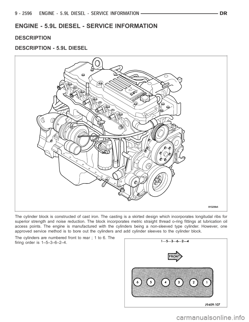
The cylinder block is constructed of cast iron. The casting is a skirted design which incorporates longitudal ribs for
superior strength and noise reduction. The block incorporates metric straight thread o-ring fittings at lubrication oil
access points. The engine is manufactured with the cylinders being a non-sleeved type cylinder. However, one
approved service method is to bore out the cylinders and add cylinder sleeves to the cylinder block.
The cylinders are numbered front to rear ; 1 to 6. The
firing order is 1–5–3–6–2–4.
Page 1906 of 5267
DESCRIPTION - CRANKCASE BREATHER
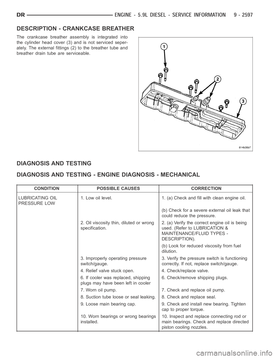
The crankcase breather assembly is integrated into
the cylinder head cover (3) and is not serviced seper-
ately. The external fittings (2) to the breather tube and
breather drain tube are serviceable.
DIAGNOSIS AND TESTING
DIAGNOSIS AND TESTING - ENGINE DIAGNOSIS - MECHANICAL
CONDITION POSSIBLE CAUSES CORRECTION
LUBRICATING OIL
PRESSURE LOW1. Low oil level. 1. (a) Check and fill with clean engine oil.
(b) Check for a severe external oil leak that
could reduce the pressure.
2. Oil viscosity thin, diluted or wrong
specification.2. (a) Verify the correct engine oil is being
used. (Refer to LUBRICATION &
MAINTENANCE/FLUID TYPES -
DESCRIPTION).
(b) Look for reduced viscosity from fuel
dilution.
3. Improperly operating pressure
switch/gauge.3. Verify the pressure switch is functioning
correctly. If not, replace switch/gauge.
4. Relief valve stuck open. 4. Check/replace valve.
6. If cooler was replaced, shipping
plugs may have been left in cooler6. Check/remove shipping plugs.
7. Worn oil pump. 7. Check and replace oil pump.
8. Suction tube loose or seal leaking. 8. Check and replace seal.
9. Loose main bearing cap. 9. Check and install new bearing. Tighten
cap to proper torque.
10. Worn bearings or wrong bearings
installed.10. Inspect and replace connecting rod or
main bearings. Check and replace directed
piston cooling nozzles.
Page 1910 of 5267

EXCESSIVE WHITE SMOKE
POSSIBLE CAUSE CORRECTION
Fuel filter plugged. Refer to Powertrain Diagnostic Manual for fuel system
testing.
Fuel grade not correct or fuel quality is poor. Temporarily change fuel brands and note condition.
Change brand if necessary.
Fuel heater element or fuel heater temperature sensor
malfunctioning. This will cause wax type build-up in fuel
filter.Refer to Fuel Heater Testing (Refer to 14 - FUEL
SYSTEM/FUEL DELIVERY/FUEL HEATER -
DIAGNOSIS AND TESTING).
Fuel injector malfunctioning. A DTC should have been set. Perform “Cylinder
Performance Test
orCylinder cutout Testusing DRB
scan tool to isolate individual cylinders. Also refer to
Powertrain Diagnostic Procedures Information and,
(Refer to 14 - FUEL SYSTEM/FUEL INJECTION/FUEL
INJECTOR - DIAGNOSIS AND TESTING).
Fuel injector hold-downs loose. Torque to specifications.
Fuel injector protrusion not correct. Check washer (shim) at bottom of fuel injector for
correct thickness. (Referto 14 - FUEL SYSTEM/FUEL
INJECTION/FUEL INJECTOR - INSTALLATION)
Fuel injection pump malfunctioning. A DTC should have been set. Refer to Powertrain
Diagnostic Procedures Information.
Fuel supply side restriction. Refer to Powertrain Diagnostic Manual for fuel system
testing.
Fuel transfer (lift) pump malfunctioning. A DTC may have been set. Refer toPowertrain
Diagnostic Procedures Information.
Intake/Exhaust valve adjustments not correct (too tight). (Refer to 9 - ENGINE/CYLINDER HEAD/INTAKE/
EXHAUST VALVES & SEATS - STANDARD
PROCEDURE).
Intake manifold air temperature sensor malfunctioning. A DTC should havebeen set. Refer to Powertrain
Diagnostic Procedures Information.
Intake manifold heater circuit not functioning correctly in
cold weather.A DTC should have been set. Refer to Powertrain
Diagnostic Procedures Information. Also check heater
elements for correct operation.
Intake manifold heater elements not functioning
correctly in cold weather.A DTC should have been set if heater elements are
malfunctioning. Refer to Powertrain Diagnostic
Procedures Information.
Internal engine damage (scuffed cylinder). Analyze engine oil and inspect oil filter to locate area of
probable damage.
Restriction in fuel supply side of fuel system. Refer to Powertrain Diagnostic Manual for fuel system
testing.
EXCESSIVE BLUE SMOKE
POSSIBLE CAUSE CORRECTION
Dirty air cleaner or restricted turbocharger intake duct. Check Filter Minder
at air filter housing. (Refer to 9 -
ENGINE/AIR INTAKE SYSTEM/AIR CLEANER
ELEMENT - REMOVAL).
Air leak in boost system between turbocharger
compressor outlet and intake manifold.Service air charge system..
Obstruction in exhaust manifold. Remove exhaust manifold and inspect forblockage
(Refer to 9 - ENGINE/MANIFOLDS/EXHAUST
MANIFOLD - REMOVAL).
Page 1948 of 5267
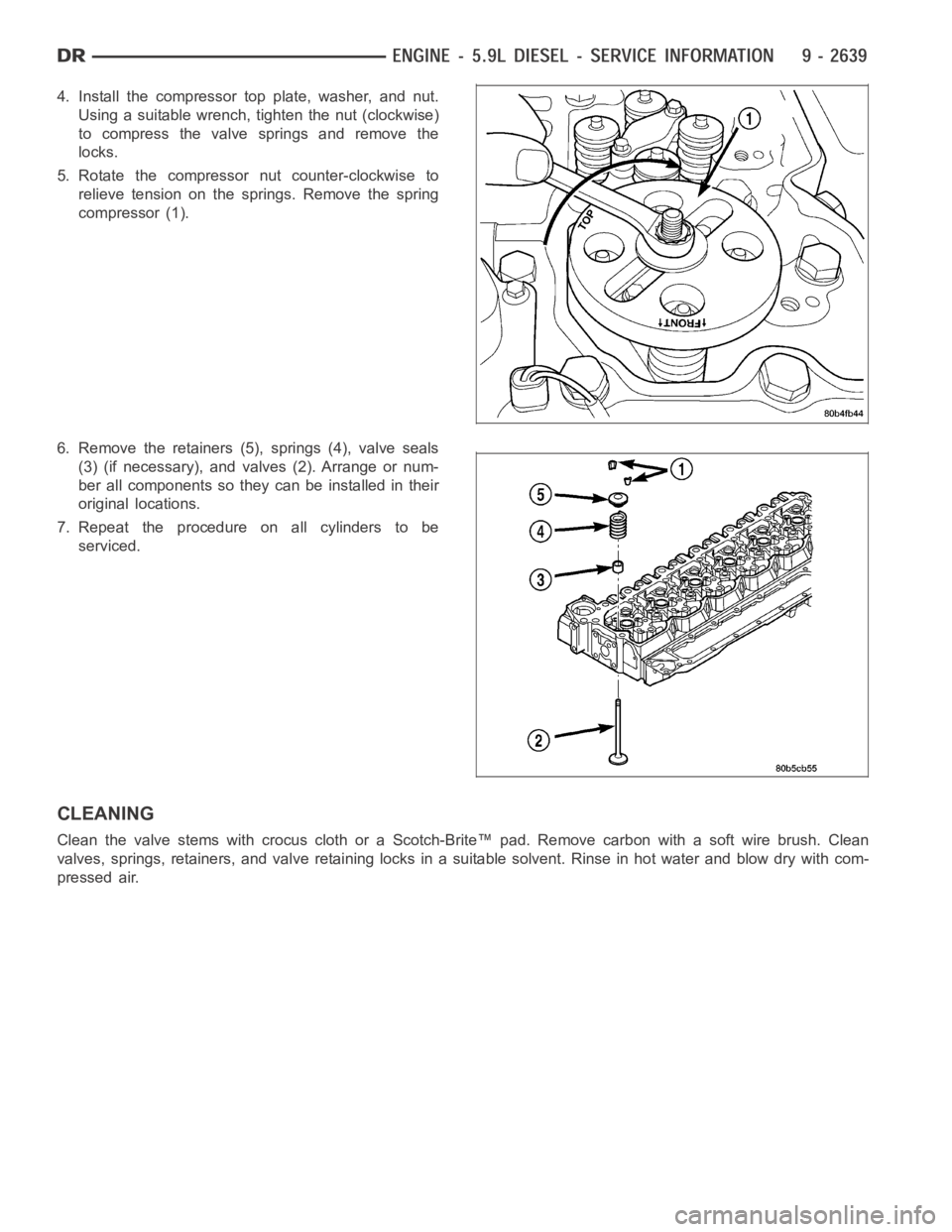
4. Install the compressor top plate, washer, and nut.
Using a suitable wrench, tighten the nut (clockwise)
to compress the valve springs and remove the
locks.
5. Rotate the compressor nut counter-clockwise to
relieve tension on the springs. Remove the spring
compressor (1).
6. Remove the retainers (5), springs (4), valve seals
(3) (if necessary), and valves (2). Arrange or num-
ber all components so they can be installed in their
original locations.
7. Repeat the procedure on all cylinders to be
serviced.
CLEANING
Clean the valve stems with crocus cloth or a Scotch-Brite™ pad. Remove carbonwithasoftwirebrush.Clean
valves, springs, retainers, and valve retaining locks in a suitable solvent. Rinse in hot water and blow dry with com-
pressed air.
Page 1953 of 5267
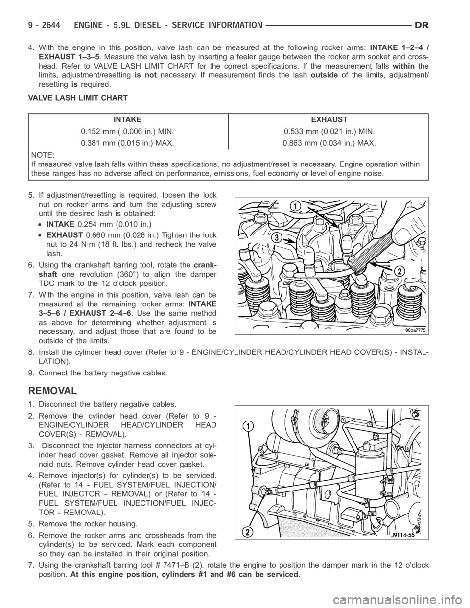
4. With the engine in this position, valve lash can be measured at the following rocker arms:INTAKE 1–2–4 /
EXHAUST 1–3–5. Measure the valve lash by inserting a feeler gauge between the rocker arm socket and cross-
head. Refer to VALVE LASH LIMIT CHART for the correct specifications. If the measurement fallswithinthe
limits, adjustment/resettingis notnecessary. If measurement finds the lashoutsideof the limits, adjustment/
resettingisrequired.
VALVE LASH LIMIT CHART
INTAKE EXHAUST
0.152 mm ( 0.006 in.) MIN. 0.533 mm (0.021 in.) MIN.
0.381 mm (0.015 in.) MAX. 0.863 mm (0.034 in.) MAX.
NOTE:
If measured valve lash falls within these specifications, no adjustment/reset is necessary. Engine operation within
these ranges has no adverse affect on performance, emissions, fuel economy or level of engine noise.
5. If adjustment/resetting is required, loosen the lock
nut on rocker arms and turn the adjusting screw
until the desired lash is obtained:
INTAKE0.254 mm (0.010 in.)
EXHAUST0.660 mm (0.026 in.) Tighten the lock
nut to 24 Nꞏm (18 ft. lbs.) and recheck the valve
lash.
6. Using the crankshaft barring tool, rotate thecrank-
shaftone revolution (360°) to align the damper
TDC mark to the 12 o’clock position.
7. With the engine in this position, valve lash can be
measured at the remaining rocker arms:INTAKE
3–5–6 / EXHAUST 2–4–6. Use the same method
as above for determining whether adjustment is
necessary, and adjust those that are found to be
outside of the limits.
8. Install the cylinder head cover (Refer to 9 - ENGINE/CYLINDER HEAD/CYLINDER HEAD COVER(S) - INSTAL-
LATION).
9. Connect the battery negative cables.
REMOVAL
1. Disconnect the battery negative cables.
2. Remove the cylinder head cover (Refer to 9 -
ENGINE/CYLINDER HEAD/CYLINDER HEAD
COVER(S) - REMOVAL).
3. Disconnect the injector harness connectors at cyl-
inder head cover gasket. Remove all injector sole-
noid nuts. Remove cylinder head cover gasket.
4. Remove injector(s) for cylinder(s) to be serviced.
(Refer to 14 - FUEL SYSTEM/FUEL INJECTION/
FUELINJECTOR-REMOVAL)or(Referto14-
FUEL SYSTEM/FUEL INJECTION/FUEL INJEC-
TOR - REMOVAL).
5. Remove the rocker housing.
6. Remove the rocker arms and crossheads from the
cylinder(s) to be serviced. Mark each component
so they can be installed in their original position.
7. Using the crankshaft barring tool # 7471–B (2), rotate the engine to position the damper mark in the 12 o’clock
position.At this engine position, cylinders #1 and #6 can be serviced.
Page 1955 of 5267
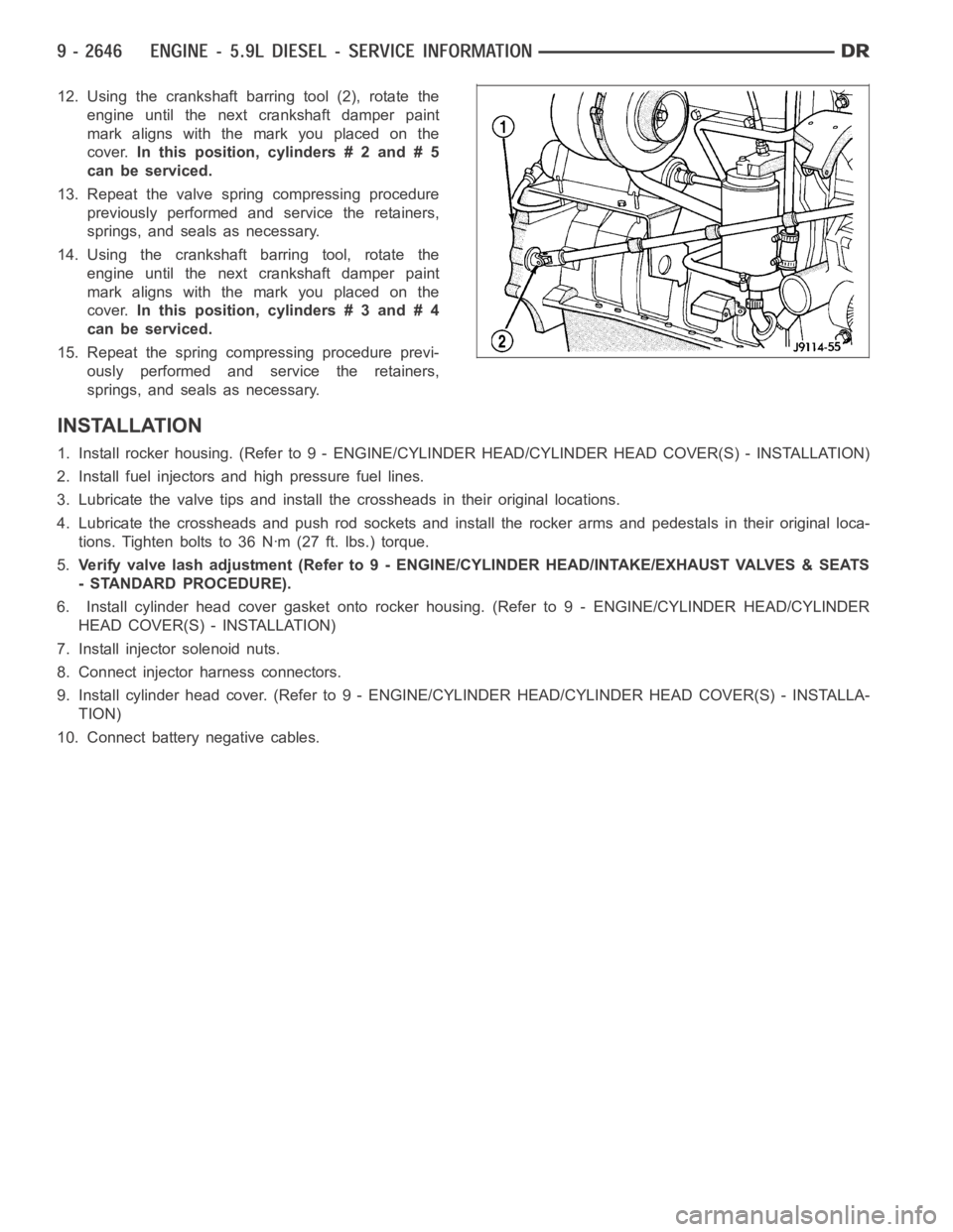
12. Using the crankshaft barring tool (2), rotate the
engine until the next crankshaft damper paint
mark aligns with the mark you placed on the
cover.In this position, cylinders # 2 and # 5
can be serviced.
13. Repeat the valve spring compressing procedure
previously performed and service the retainers,
springs, and seals as necessary.
14. Using the crankshaft barring tool, rotate the
engine until the next crankshaft damper paint
mark aligns with the mark you placed on the
cover.In this position, cylinders # 3 and # 4
can be serviced.
15. Repeat the spring compressing procedure previ-
ously performed and service the retainers,
springs, and seals as necessary.
INSTALLATION
1. Install rocker housing. (Refer to 9 -ENGINE/CYLINDER HEAD/CYLINDER HEAD COVER(S) - INSTALLATION)
2. Install fuel injectors and high pressure fuel lines.
3. Lubricate the valve tips and install the crossheads in their original locations.
4. Lubricate the crossheads and push rod sockets and install the rocker arms and pedestals in their original loca-
tions. Tighten bolts to 36 Nꞏm (27 ft. lbs.) torque.
5.Verify valve lash adjustment (Refer to 9 - ENGINE/CYLINDER HEAD/INTAKE/EXHAUST VALVES & SEATS
- STANDARD PROCEDURE).
6. Install cylinder head cover gasket onto rocker housing. (Refer to 9 - ENGINE/CYLINDER HEAD/CYLINDER
HEAD COVER(S) - INSTALLATION)
7. Install injector solenoid nuts.
8. Connect injector harness connectors.
9. Install cylinder head cover. (Refer to 9 - ENGINE/CYLINDER HEAD/CYLINDER HEAD COVER(S) - INSTALLA-
TION)
10. Connect battery negative cables.