2006 DODGE RAM SRT-10 service
[x] Cancel search: servicePage 2072 of 5267
SPRINGS/SEALS-VALVE
DIAGNOSIS AND TESTING
VA LV E S P R I N G T E S T I N G
The valve springs should be tested whenever
removed for inspection, reconditioning, or replace-
ment.
1. Obtain specifications for spring tension at specified
spring length (Refer to 9 - ENGINE - SPECIFICA-
TIONS).
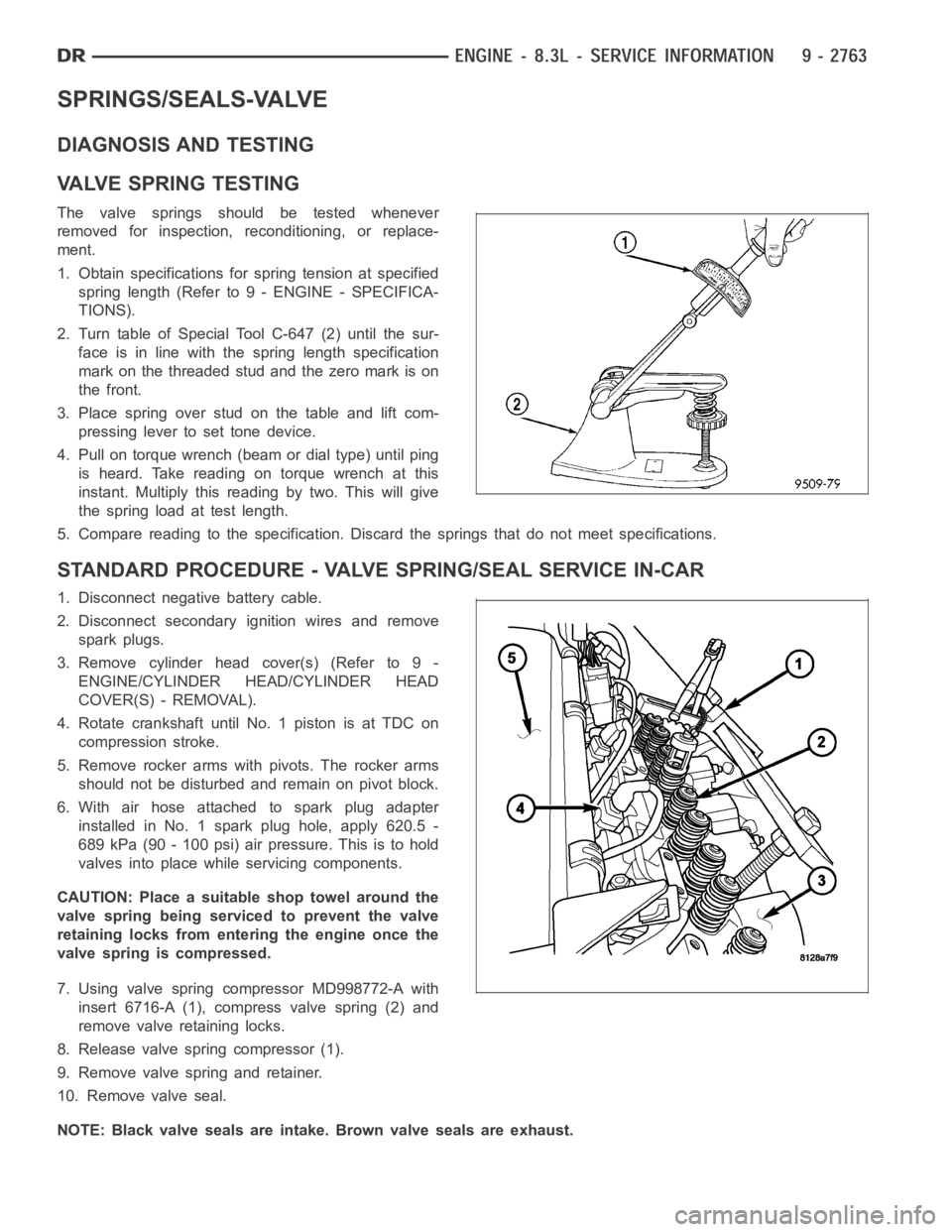
2. Turn table of Special Tool C-647 (2) until the sur-
face is in line with the spring length specification
mark on the threaded stud and the zero mark is on
the front.
3.Placespringoverstudonthetableandliftcom-
pressing lever to set tone device.
4. Pull on torque wrench (beam or dial type) until ping
is heard. Take reading on torque wrench at this
instant. Multiply this reading by two. This will give
the spring load at test length.
5. Compare reading to the specification. Discard the springs that do not meet specifications.
STANDARD PROCEDURE - VALVE SPRING/SEAL SERVICE IN-CAR
1. Disconnect negative battery cable.
2. Disconnect secondary ignition wires and remove
spark plugs.
3. Remove cylinder head cover(s) (Refer to 9 -
ENGINE/CYLINDER HEAD/CYLINDER HEAD
COVER(S) - REMOVAL).
4. Rotate crankshaft until No. 1 piston is at TDC on
compression stroke.
5. Remove rocker arms with pivots. The rocker arms
should not be disturbed and remain on pivot block.
6. With air hose attached to spark plug adapter
installed in No. 1 spark plug hole, apply 620.5 -
689 kPa (90 - 100 psi) air pressure. This is to hold
valves into place while servicing components.
CAUTION: Place a suitable shop towel around the
valve spring being serviced to prevent the valve
retaining locks from entering the engine once the
valve spring is compressed.
7. Using valve spring compressor MD998772-A with
insert 6716-A (1), compress valve spring (2) and
remove valve retaining locks.
8. Release valve spring compressor (1).
9. Remove valve spring and retainer.
10. Remove valve seal.
NOTE: Black valve seals are intake. Brown valve seals are exhaust.
Page 2076 of 5267
INSPECTION
Va l v e
1. Clean valves thoroughly and discard any burned,
bent, warped, and cracked valves.
2. Measure valve stems for wear (Refer to 9 -
ENGINE - SPECIFICATIONS).
NOTE: Valve stems are chrome plated and should
not be polished.
Valve Guide
1. Remove carbon and varnish deposits from inside of
valve guides with a reliable guide cleaner.
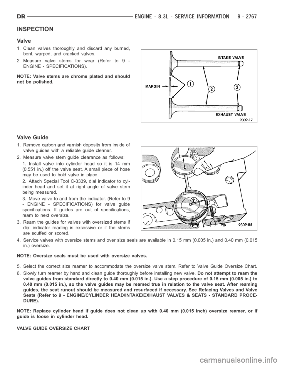
2. Measure valve stem guide clearance as follows:
1. Install valve into cylinder head so it is 14 mm
(0.551 in.) off the valve seat. A small piece of hose
maybeusedtoholdvalveinplace.
2. Attach Special Tool C-3339, dial indicator to cyl-
inder head and set it at right angle of valve stem
being measured.
3. Move valve to and from the indicator. (Refer to 9
- ENGINE - SPECIFICATIONS) for valve guide
specifications. If guides are out of specifications,
ream to next oversize.
3. Ream the guides for valves with oversized stems if
dial indicator reading is excessive or if the stems
are scuffed or scored.
4. Service valves with oversize stems and over size seals are available in 0.15 mm (0.005 in.) and 0.40 mm (0.015
in.) oversize.
NOTE: Oversize seals must be used with oversize valves.
5. Select the correct size reamer to accommodate the oversize valve stem. Refer to Valve Guide Oversize Chart.
6. Slowly turn reamer by hand and clean guide thoroughly before installingnew valve.Do not attempt to ream the
valve guides from standard directly to 0.40 mm (0.015 in.). Use a step procedure of 0.15 mm (0.005 in.) to
0.40 mm (0.015 in.), so the valve guides may be reamed true in relation to thevalve seat. After reaming
guides, the seat runout should be measured and resurfaced if necessary. See Refacing Valves and Valve
Seats (Refer to 9 - ENGINE/CYLINDER HEAD/INTAKE/EXHAUST VALVES & SEATS - STANDARD PROCE-
DURE).
NOTE: Replace cylinder head if guide does not clean up with 0.40 mm (0.015 inch) oversize reamer, or if
guide is loose in cylinder head.
VALVE GUIDE OVERSIZE CHART
Page 2086 of 5267
LUBRICATION
DESCRIPTION
The engine lubrication system is a full-flow filtration pressure feed type.
OPERATION
Engine oil stored in the oil pan is taken in and discharged by an internal geartypeoilpump,whichisdrivenbythe
crankshaft. A pressure relief valve is located in the timing chain case cover; it regulates oil pressure. The oil is
pumped through an oil filter and feeds a main oil gallery. Also, oil is routedtoanexternaloilcooler.Themainoil
gallery feeds oil under pressure to the main bearings, connecting rod bearings, and camshaft bearings. Passages in
the cylinder block feed oil to the hydraulic lifters. The oil then flows through hollow pushrods, which feed the rocker
arm pivots.
DIAGNOSIS AND TESTING
CHECKING ENGINE OIL PRESSURE
1. Remove oil pressure sensor (Refer to 9 - ENGINE/LUBRICATION/OIL PRESSURE SENSOR - REMOVAL).
2. Install oil pressure gauge.
3. Warm engine at high idle until thermostat opens.
CAUTION: If oil pressure is 0 at idle, Do Not Run engine at 3000 RPM.
4. Oil pressure should be 68.9 kPa (10 psi) at idle or 310 - 517 kPa (45 - 75 psi)at 3000 RPM.
5. If oil pressure is 0 at idle, shut off engine. Check for a clogged oil pick-up screen or a pressure relief valve stuck
open.
ENGINE OIL LEAK
Begin with a thorough visual inspection of the engine, particularly at thearea of the suspected leak. If an oil leak
source is not readily identifiable, thefollowingstepsshouldbefollowed:
1. Do not clean or degrease the engine at this time because some solvents maycause rubber to swell, temporarily
stopping the leak.
2. Add an oil soluble dye (use as recommended by manufacturer). Start the engine and let idle for approximately 15
minutes. Check the oil dipstick to make sure the dye is thoroughly mixed as indicated with a bright yellow color
under a black light.
3. Using a black light, inspect the entire engine for fluorescent dye, particularly at the suspected area of oil leak. If
the oil leak is found and identified, repair per service manual instructions.
4. If dye is not observed, drive the vehicle at various speeds for approximately 24 km (15 miles), and repeat inspec-
tion.If the oil leak source is not positively identified at this time, proceed with the air leak detection test
method.
Air Leak Detection Test Method
1. Remove the PCV valve from the IAFM. Cap or plug the PCV valve grommet.
2. Attach an air hose with pressure gauge and regulator to the dipstick tube.
CAUTION: Do not subject the engine assembly to more than 20.6 kPa (3 PSI) of test pressure.
3. Gradually apply air pressure from 6.89 - 17.23 kPa (1 - 2.5 psi) maximum while applying soapy water at the
suspected source. Adjust the regulator to the suitable test pressure thatprovide the best bubbles which will pin-
point the leak source. If the oil leak is detected and identified, repair per service manual procedures.
4. If the leakage occurs at the rear oil seal area, refer to the section, Inspection for Rear Seal Area Leak.
5. If no leaks are detected, turn off the air supply and remove the air hose and all plugs and caps. Install the PCV
valve.
6. Clean the oil off the suspect oil leak area using a suitable solvent. Drive the vehicle at various speeds approx-
imately 24 km (15 miles). Inspect the engine for signs of an oil leak by usinga black light.
Page 2097 of 5267
PUMP-OIL
REMOVAL
NOTE: The oil pump is serviced with the timing
chain cover.
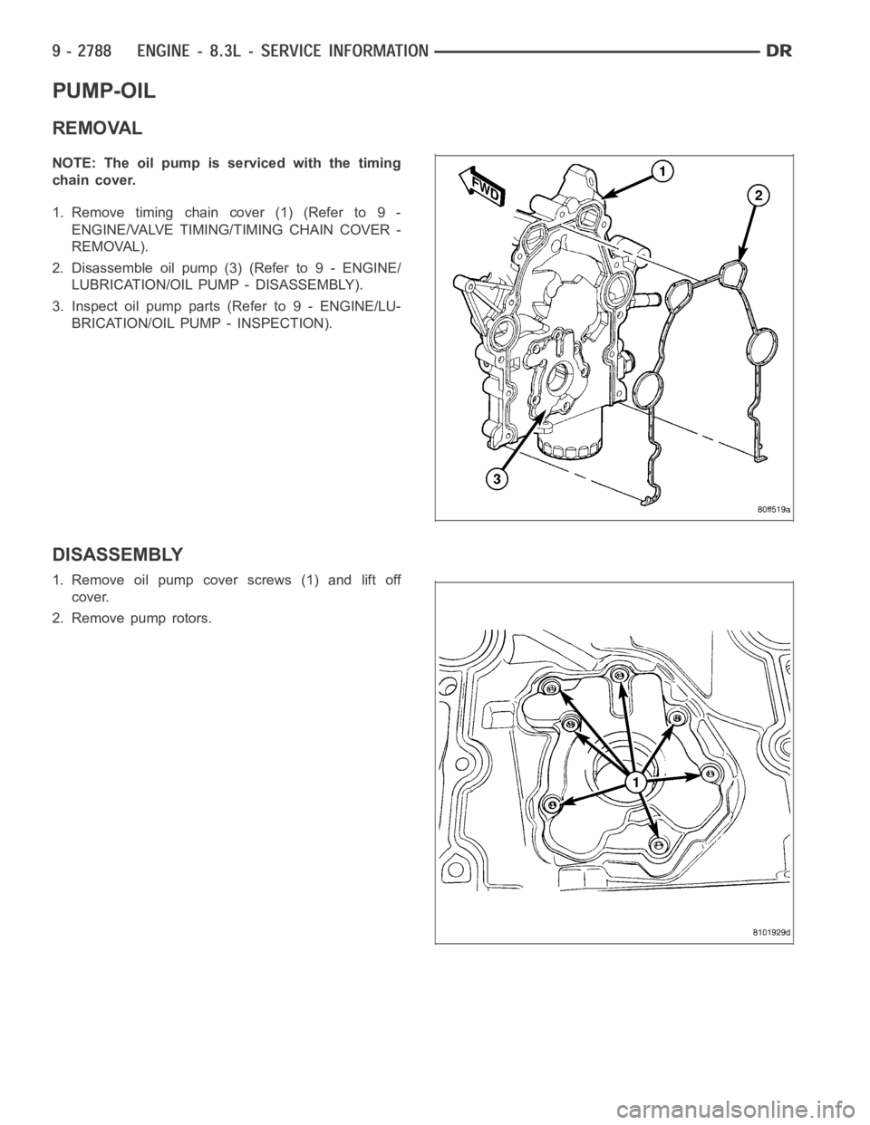
1. Remove timing chain cover (1) (Refer to 9 -
ENGINE/VALVE TIMING/TIMING CHAIN COVER -
REMOVAL).
2. Disassemble oil pump (3) (Refer to 9 - ENGINE/
LUBRICATION/OIL PUMP - DISASSEMBLY).
3. Inspect oil pump parts (Refer to 9 - ENGINE/LU-
BRICATION/OIL PUMP - INSPECTION).
DISASSEMBLY
1. Remove oil pump cover screws (1) and lift off
cover.
2. Remove pump rotors.
Page 2104 of 5267
BLOCK-ENGINE
DESCRIPTION
The cylinder block is made of a sand-cast aluminum alloy. The cylinder block has interference-fit cast iron cylinder
liners. The cylinder liners are thermally installed during block manufacturing; they are not serviceable items.
Six iron main bearing caps use four bolts per cap; two vertical and two horizontal. A crankshaft oil scraper is
attached to the main bearing caps via extended main bearing cap bolts and nuts.
STANDARD PROCEDURE - CYLINDER BORE HONING
Before honing, stuff plenty of clean shop towels under
the bores and over the crankshaft to keep abrasive
materials from entering the crankshaft area.
1. Used carefully, the Cylinder Bore Sizing Hone
C-823, equipped with 220 grit stones, is the best
tool for this job. In addition to deglazing, it will
reduce taper and out-of-round, as well as removing
light scuffing, scoring and scratches. Usually, a few
strokes will clean up a bore and maintain the
required limits.
CAUTION: DO NOT use rigid type hones to remove
cylinder wall glaze.
2. Deglazing of the cylinder walls may be done if the
cylinder bore is straight and round. Use a cylinder
surfacing hone, Honing Tool C-3501, equipped with
280 grit stones (C-3501-3810). about 20-60
strokes, depending on the bore condition, will be
sufficient to provide a satisfactory surface. Using
honing oil C-3501-3880, or a light honing oil, avail-
able from major oil distributors.
CAUTION: DO NOT use engine or transmission oil, mineral spirits, or kerosene.
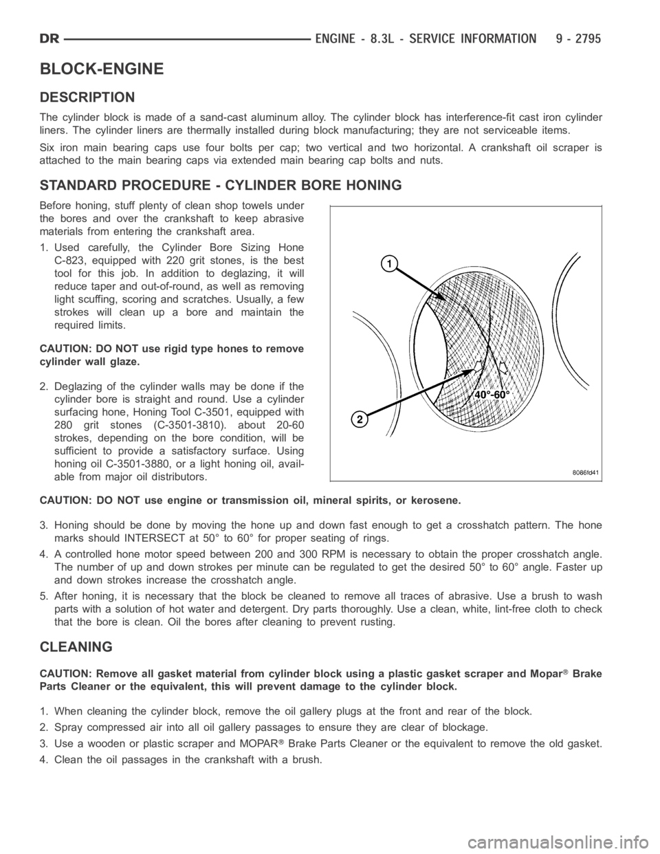
3. Honing should be done by moving the hone up and down fast enough to get a crosshatch pattern. The hone
marks should INTERSECT at 50° to 60° for proper seating of rings.
4. A controlled hone motor speed between 200 and 300 RPM is necessary to obtain the proper crosshatch angle.
The number of up and down strokes per minute can be regulated to get the desired 50° to 60° angle. Faster up
and down strokes increase the crosshatch angle.
5. After honing, it is necessary that the block be cleaned to remove all traces of abrasive. Use a brush to wash
parts with a solution of hot water and detergent. Dry parts thoroughly. Usea clean, white, lint-free cloth to check
that the bore is clean. Oil the bores after cleaning to prevent rusting.
CLEANING
CAUTION: Remove all gasket material from cylinder block using a plastic gasket scraper and MoparBrake
Parts Cleaner or the equivalent, this will prevent damage to the cylinder block.
1. When cleaning the cylinder block, remove the oil gallery plugs at the front and rear of the block.
2. Spray compressed air into all oil gallery passages to ensure they are clear of blockage.
3. Use a wooden or plastic scraper and MOPAR
Brake Parts Cleaner or the equivalent to remove the old gasket.
4. Clean the oil passages in the crankshaft with a brush.
Page 2111 of 5267
ROD-PISTON & CONNECTING
DESCRIPTION
The pistons are made of cast aluminum with an added anodized coating on bothsides of the skirt and the top
piston ring groove for reduced wear and it’s low friction properties. Three piston rings are used; two compression
and one three-piece oil control ring. The piston pin (press-fit into the rods) joins the piston to a forged steel, frac-
tured cap, designed connecting rod, with a custom twelve point nine millimeter threaded bolt. The piston and con-
necting rod is serviced as an assembly and is not interchangeable with previous model years.
STANDARD PROCEDURE
PISTON FITTING
All pistons are machined to the same weight in grams,
to maintain piston balance.
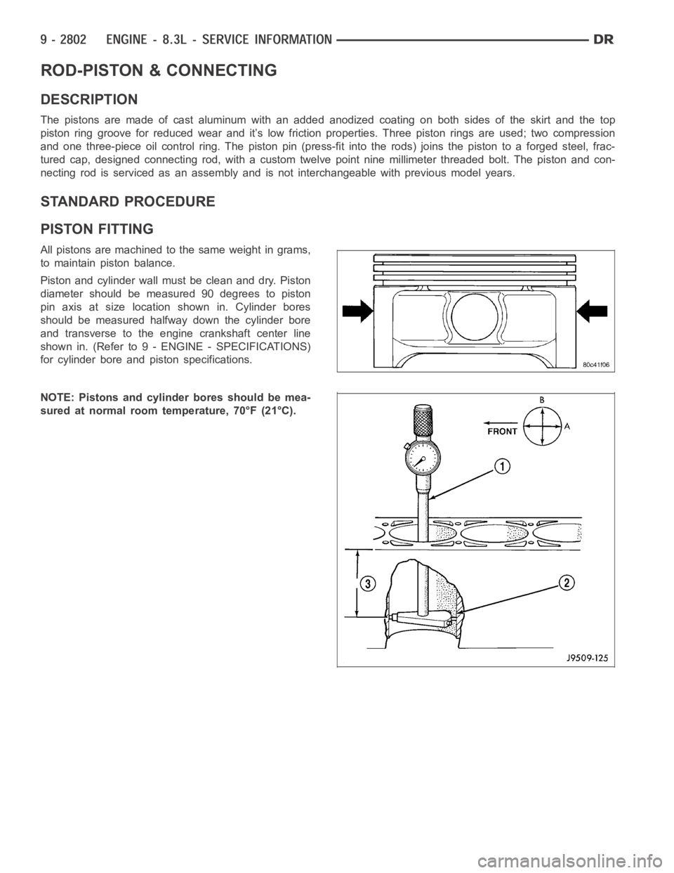
Piston and cylinder wall must be clean and dry. Piston
diameter should be measured 90 degrees to piston
pin axis at size location shown in. Cylinder bores
should be measured halfway down the cylinder bore
and transverse to the engine crankshaft center line
shown in. (Refer to 9 - ENGINE - SPECIFICATIONS)
for cylinder bore and piston specifications.
NOTE: Pistons and cylinder bores should be mea-
sured at normal room temperature, 70°F (21°C).
Page 2114 of 5267
PISTON
1. Inspect all piston surfaces for nicks and scuffs.
2. Inspect piston and ring grooves for wear.
INSTALLATION
NOTE: Pistons and connecting rods are serviced
as an assembly. Left bank pistons are labeled
“ODD”. Right bank pistons are labeled “EVEN”.
1. Install piston rings (Refer to 9 - ENGINE/ENGINE
BLOCK/PISTON RINGS - INSTALLATION).
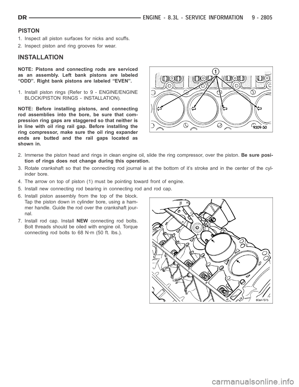
NOTE: Before installing pistons, and connecting
rod assemblies into the bore, be sure that com-
pression ring gaps are staggered so that neither is
in line with oil ring rail gap. Before installing the
ring compressor, make sure the oil ring expander
ends are butted and the rail gaps located as
shown in.
2. Immerse the piston head and rings in clean engine oil, slide the ring compressor, over the piston.Be sure posi-
tion of rings does not change during this operation.
3. Rotate crankshaft so that the connecting rod journal is at the bottom of it’s stroke and in the center of the cyl-
inder bore.
4. The arrow on top of piston (1) must be pointing toward front of engine.
5. Install new connecting rod bearing in connecting rod and rod cap.
6. Install piston assembly from the top of the block.
Tap the piston down in cylinder bore, using a ham-
mer handle. Guide the rod over the crankshaft jour-
nal.
7. Install rod cap. InstallNEWconnecting rod bolts.
Bolt threads should be oiled with engine oil. Torque
connecting rod bolts to 68 Nꞏm (50 ft. lbs.).
Page 2124 of 5267
SEAL-OIL-REAR-CRANK AND RETAINER
REMOVAL
1. Remove transmission (Refer to 21 - TRANSMIS-
SION/TRANSAXLE/MANUAL - REMOVAL).
2. Remove clutch and flywheel (Refer to 6 - CLUTCH/
CLUTCH DISC - REMOVAL).
NOTE: The oil seal and retainer are serviced as an
assembly.
3. Remove the seal retainer bolts from cylinder block
and oil pan.
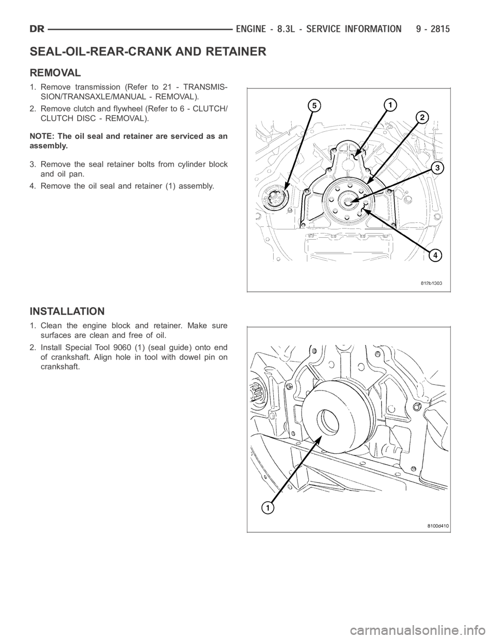
4. Remove the oil seal and retainer (1) assembly.
INSTALLATION
1. Clean the engine block and retainer. Make sure
surfaces are clean and free of oil.
2. Install Special Tool 9060 (1) (seal guide) onto end
of crankshaft. Align hole in tool with dowel pin on
crankshaft.