2006 DODGE RAM SRT-10 service
[x] Cancel search: servicePage 2303 of 5267
INSTALLATION
3.7L V-6
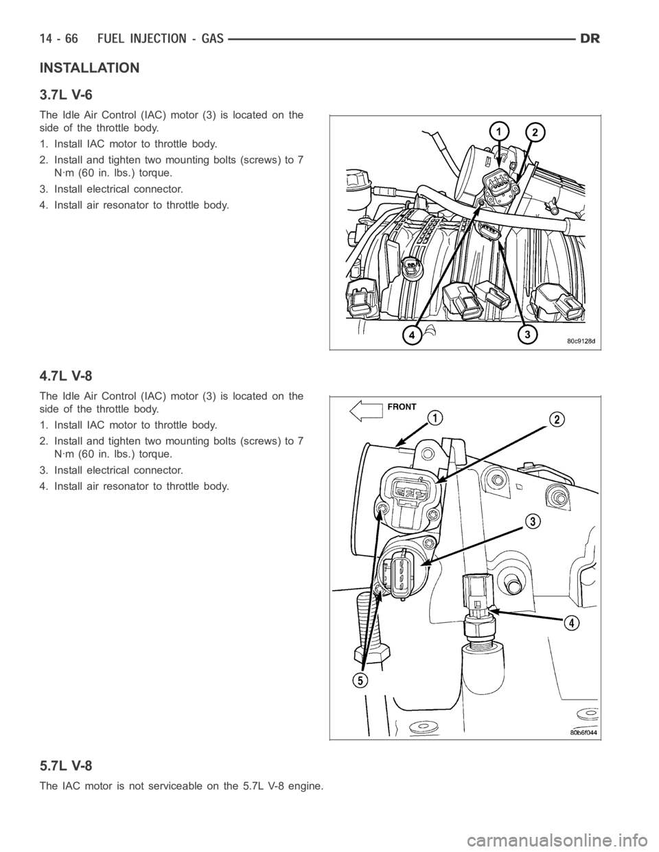
The Idle Air Control (IAC) motor (3) is located on the
side of the throttle body.
1. Install IAC motor to throttle body.
2. Install and tighten two mounting bolts (screws) to 7
Nꞏm (60 in. lbs.) torque.
3. Install electrical connector.
4. Install air resonator to throttle body.
4.7L V-8
The Idle Air Control (IAC) motor (3) is located on the
side of the throttle body.
1. Install IAC motor to throttle body.
2. Install and tighten two mounting bolts (screws) to 7
Nꞏm (60 in. lbs.) torque.
3. Install electrical connector.
4. Install air resonator to throttle body.
5.7L V-8
The IAC motor is not serviceable on the 5.7L V-8 engine.
Page 2343 of 5267
Fuel enters the system from the electric fuel transfer (lift) pump, which is located inside of the fuel tank and attached
to the fuel tank module (the fuel transfer pump is no longer attached to the engine). Fuel is forced through the fuel
filter element and then enters the Fuel Pump/Gear Pump, which is attached to the rear of the fuel injection pump.
The Fuel Pump/Gear Pump is a low-pressure pump and produce pressures ranging from 551.5 kpa (80 psi) to 1241
kpa (180) psi. Fuel then enters the fuel injection pump. Low pressure fuel is then supplied to the FCA (Fuel Control
Actuator).
The FCA is an electronically controlled solenoid valve. The ECM controls the amount of fuel that enters the high-
pressure pumping chambers by opening and closing the FCA based on a demanded fuel pressure. The FPS (Fuel
Pressure Sensor) on the fuel rail monitors the actual fuel pressure and provides it as an input to the ECM. When
the actuator is opened, the maximum amount of fuel is being supplied to the fuel injection pump. Any fuel that does
not enter the injection pump is directed to the overflow valve. The overflow valve regulates how much excess fuel
is used for lubrication of the pump and how much is returned to the tank through the drain manifold.
Fuel entering the injection pump is pressurized to between 300-1600 bar (4351-23,206 psi) by three radial pumping
chambers. The pressurized fuel is then supplied to the fuel rail.
STANDARD PROCEDURE
WATER DRAINING AT FUEL FILTER
Refer to Fuel Filter/Water Separatorremoval/installation for procedures.
CLEANING FUEL SYSTEM PARTS
CAUTION: Cleanliness cannot be overemphasized when handling or replacingdieselfuelsystemcompo-
nents. This especially includes the fuel injectors, high-pressure fuel lines and fuel injection pump. Very tight
tolerances are used with these parts. Dirt contamination could cause rapid part wear and possible plugging
of fuel injector nozzle tip holes. This in turn could lead to possible engine misfire. Always wash/clean any
fuel system component thoroughly before disassembly and then air dry. Capor cover any open part after
disassembly. Before assembly, examine each part for dirt, grease or othercontaminants and clean if nec-
essary. When installing new parts, lubricate them with clean engine oil orclean diesel fuel only.
FUEL SYSTEM PRIMING
A certain amount of air becomes trappedin the fuel system when fuel system components on the supply and/or
high-pressure side are serviced or replaced. Fuel system priming is accomplished using the electric fuel transfer (lift)
pump.
Servicing or replacing fuel system components will not require fuel systempriming.
The fuel transfer (lift) pump is self-priming: When the key is first turnedon (without cranking engine), the pump
operates for approximately 1 to 2 second and then shuts off (Note: When ambient temperatures are cold enough to
cause the intake air heaters to operate, the fuel lift pump will operate during the entire intake air pre-heat cycle).
The pump will also operate for up to 25 seconds after the starter is quickly engaged, and then disengaged without
allowing the engine to start. The pump shuts off immediately if the key is onand the engine stops running.
1. Turn key to CRANK position and quickly release key to ON position before engine starts. This will operate fuel
transfer pump for approximately 25 seconds.
2. Crank engine. If the engine does not start after 25 seconds, turn key to OFF position, and leave it off for at least
5 seconds. Repeat previous step until engine starts.
3. Fuel system priming is now completed.
4. Attempt to start engine. If engine will not start, proceed to following steps.When engine does start, it may run
erratically and be noisy for a few minutes. This is a normal condition.
CAUTION: Do not engage the starter motor for more than 30 seconds at a time. Allow two minutes between
cranking intervals.
5. Perform previous fuel priming procedure steps using fuel transfer pump. Be sure fuel is present at fuel tank.
6. Crank the engine for 30 seconds at a time to allow fuel system to prime.
Page 2371 of 5267
MODULE - FUEL TANK
DESCRIPTION
.
The fuel tank module is installed in the top of the fuel tank. The fuel tank module contains the following compo-
nents:
An electric fuel transfer (lift) pump
Fuel reservoir
A separate in-tank fuel filter
Fuel gauge sending unit (fuel level sensor)
Fuel supply line connection
A special lockring to retain module to fuel tank
Fuel return line connection
OPERATION
Refer to Fuel Gauge Sending Unit.
REMOVAL
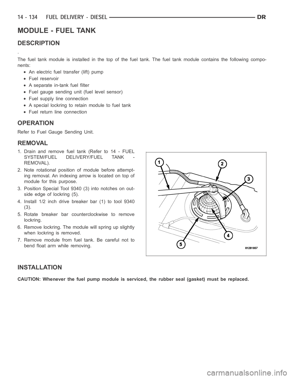
1. Drain and remove fuel tank (Refer to 14 - FUEL
SYSTEM/FUEL DELIVERY/FUEL TANK -
REMOVAL).
2. Note rotational position of module before attempt-
ing removal. An indexing arrow is located on top of
module for this purpose.
3. Position Special Tool 9340 (3) into notches on out-
side edge of lockring (5).
4. Install 1/2 inch drive breaker bar (1) to tool 9340
(3).
5. Rotate breaker bar counterclockwise to remove
lockring.
6. Remove lockring. The module will spring up slightly
when lockring is removed.
7. Remove module from fuel tank. Be careful not to
bend float arm while removing.
INSTALLATION
CAUTION: Whenever the fuel pump module is serviced, the rubber seal (gasket) must be replaced.
Page 2373 of 5267
PUMP - FUEL TRANSFER
DESCRIPTION
The fuel transfer pump (fuel lift pump) is part of the fuel pump module. The fuel pump module is located in the fuel
tank. The 12–volt electric pump is operated and controlled by the Engine Control Module (ECM). The ECM controls
a relay in the Intelligent Power Module(IPM) for transfer pump operation.
OPERATION
The purpose of the fuel transfer pump is to supply (transfer) a low-pressure fuel source:fromthe fuel tank,through
the fuel filter/water separator andtothe fuel injection pump. Here, the low-pressure is raised to a high-pressure by
the fuel injection pump for operation of the high-pressure fuel injectors. Check valves within the pump, control direc-
tion of fuel flow and prevent fuel bleed-back during engine shut down.
Maximum current flow to the pump is 5 amperes.
With the engine running, the pump has a 100 percent duty-cycle.
The transfer pump is self-priming: When the key is first turned on (withoutcranking engine), the pump will operate
for approximately 2 seconds and then shut off (Note: When ambient temperatures are cold enough to cause the
intake air heaters to operate, the fuel lift pump will operate during the entire intake air pre-heat cycle). The pump will
also operate for up to 25 seconds after the starter is engaged, and then disengaged and the engine is not running.
The pump shuts off immediately if the key is on and the engine stops running.
The fuel volume of the transfer pump will always provide more fuel than the fuel injection pump requires. Excess
fuel is returned from the injection pump through an overflow valve, and then back to the fuel tank.
REMOVAL
The fuel transfer pump (fuel lift pump) is a part of the fuel tank module. It is not serviced separately. Refer to Fuel
Tank Module Removal or Installation for procedures (Refer to 14 - FUEL SYSTEM/FUEL DELIVERY/FUEL TANK
MODULE - REMOVAL).
INSTALLATION
The fuel transfer pump (fuel lift pump) is a part of the fuel tank module. It is not serviced separately (Refer to 14 -
FUEL SYSTEM/FUEL DELIVERY/FUEL TANK MODULE - INSTALLATION).
Page 2374 of 5267
VALVE - CASCADE OVERFLOW
DESCRIPTION
NOTE: The cascade overflow valve is not serviced separately.
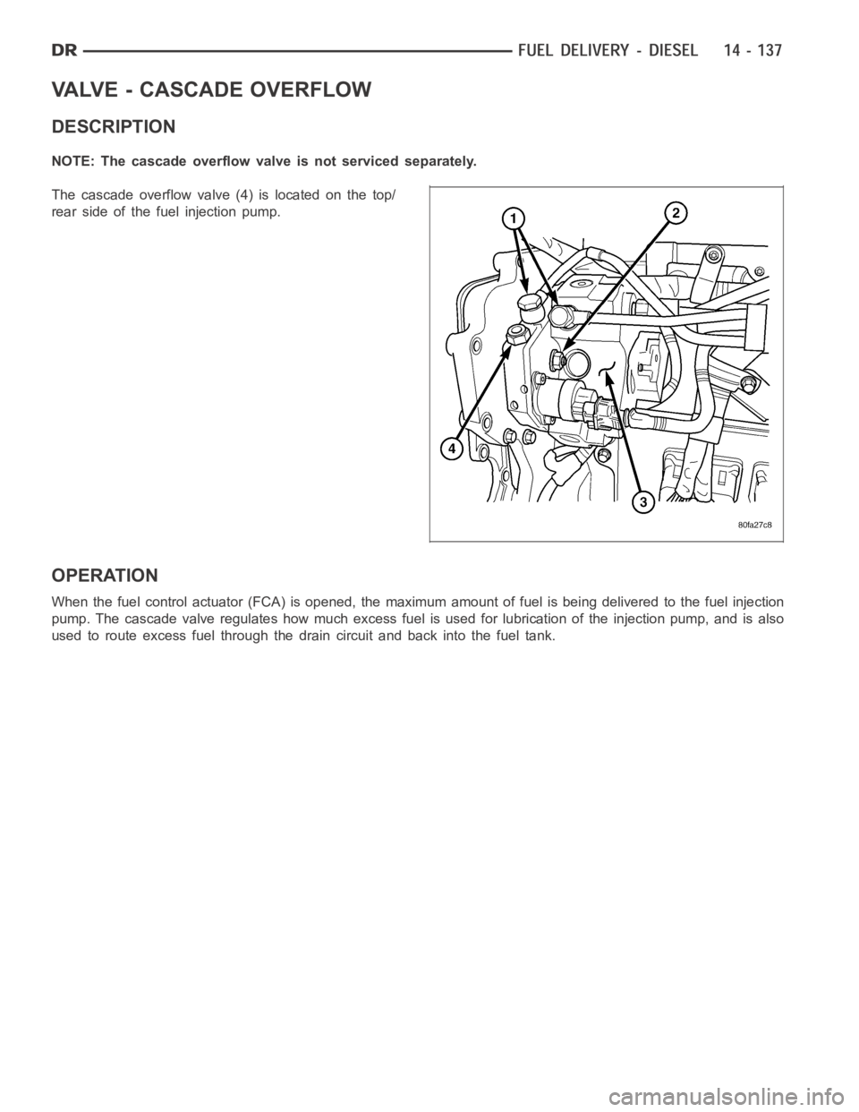
Thecascadeoverflowvalve(4)islocatedonthetop/
rear side of the fuel injection pump.
OPERATION
When the fuel control actuator (FCA) is opened, the maximum amount of fuel is being delivered to the fuel injection
pump. The cascade valve regulates how much excess fuel is used for lubrication of the injection pump, and is also
used to route excess fuel through the drain circuit and back into the fuel tank.
Page 2413 of 5267
COLUMN
DESCRIPTION
DESCRIPTION
NOTE: The steering column on vehicles with an automatic transmission may not be equipped with an inter-
nal locking shaft that allows the ignition key cylinder to be locked with the key. Alternative methods of lock-
ing the steering wheel for service will have to be used.
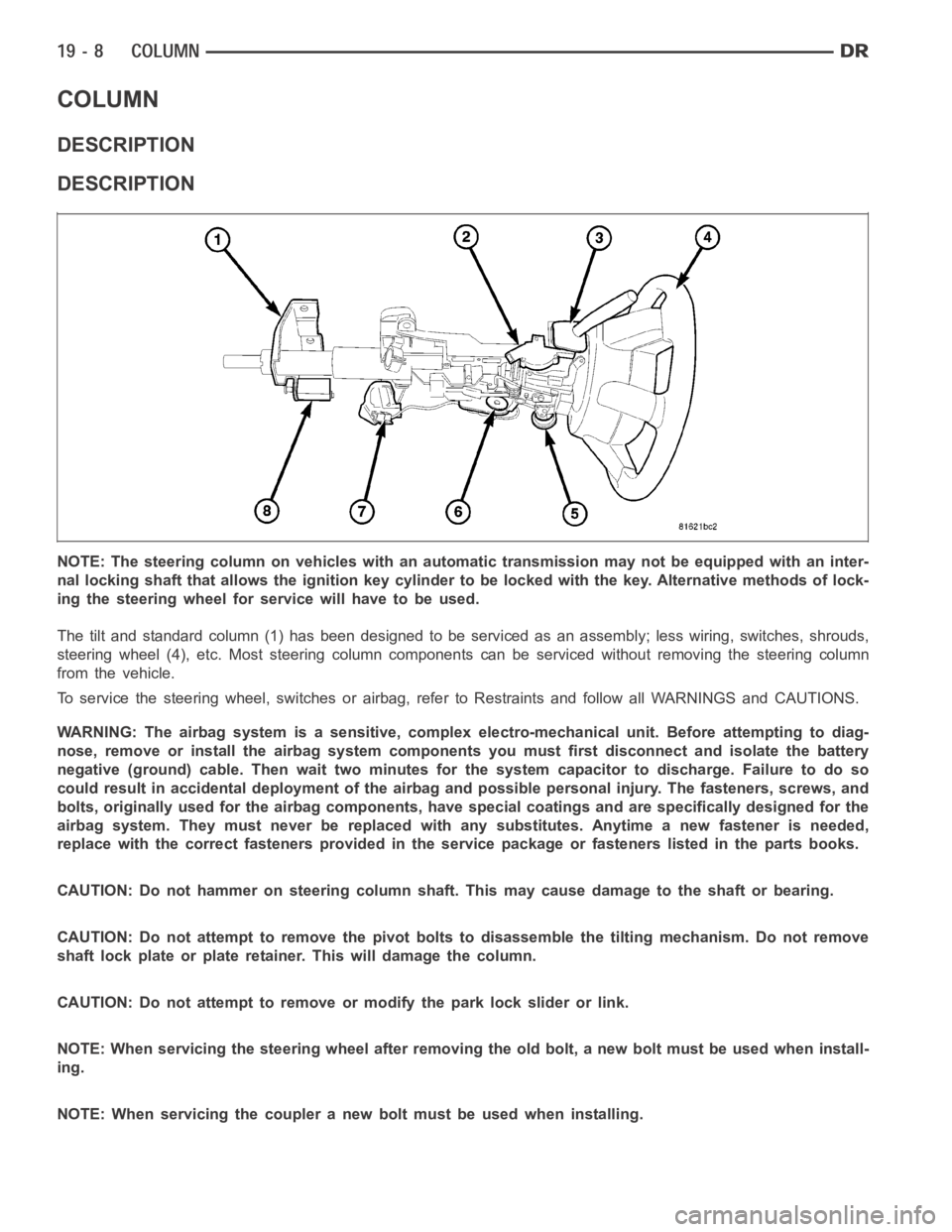
The tilt and standard column (1) has been designed to be serviced as an assembly; less wiring, switches, shrouds,
steering wheel (4), etc. Most steering column components can be serviced without removing the steering column
from the vehicle.
To service the steering wheel, switches or airbag, refer to Restraints andfollow all WARNINGS and CAUTIONS.
WARNING: The airbag system is a sensitive, complex electro-mechanical unit. Before attempting to diag-
nose, remove or install the airbag system components you must first disconnect and isolate the battery
negative (ground) cable. Then wait two minutes for the system capacitor todischarge. Failure to do so
could result in accidental deployment of the airbag and possible personalinjury. The fasteners, screws, and
bolts, originally used for the airbag components, have special coatings and are specifically designed for the
airbag system. They must never be replaced with any substitutes. Anytime anew fastener is needed,
replace with the correct fasteners provided in the service package or fasteners listed in the parts books.
CAUTION: Do not hammer on steering column shaft. This may cause damage to the shaft or bearing.
CAUTION: Do not attempt to remove the pivot bolts to disassemble the tilting mechanism. Do not remove
shaft lock plate or plate retainer. This will damage the column.
CAUTION: Do not attempt to remove or modify the park lock slider or link.
NOTE: When servicing the steering wheel after removing the old bolt, a new bolt must be used when install-
ing.
NOTE: When servicing the coupler a new bolt must be used when installing.
Page 2414 of 5267
DESCRIPTION - SRT10
The SRT-10 column has noSTARTposition on the key cylinder. The push starter button switch is mounted on the
Instrument panel center stack. All SRT-10 columns are Tilt columns, Standard cab trucks come with manual trans-
missions, Quad cab trucks come equipped with automatic transmissions.
DIAGNOSIS AND TESTING
STEERING COLUMN
If the vehicle is involved in a front end collision/the air bag has deployedthe column must be inspected. This
inspection will determine if the Column has collapsed. Inspect the columnmounting capsules visually and manually
push and pull them to check for separation or fractures. If capsules are fractured or have moved the column MUST
be replaced.
REMOVAL
WARNING: Before servicing the steering column the airbag system must be disarmed. Refer to electrical
restraint system for service procedures. Failure to do so may result in accidental deployment of the airbag
and possible personal injury.
CAUTION: All fasteners must be torqued to specification to ensure proper operation of the steering column.
1. Position the front wheelsstraight ahead.
2. Disconnect the negative (ground) cable from the battery.
3. Remove the airbag, (Refer to 8 - ELECTRICAL/RE-
STRAINTS/DRIVER AIRBAG - REMOVAL).
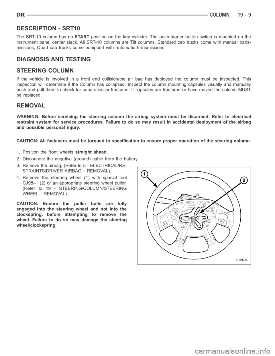
4. Remove the steering wheel (1) with special tool
CJ98–1 (2) or an appropriate steering wheel puller.
(Refer to 19 - STEERING/COLUMN/STEERING
WHEEL - REMOVAL).
CAUTION: Ensure the puller bolts are fully
engaged into the steering wheel and not into the
clockspring, before attempting to remove the
wheel. Failure to do so may damage the steering
wheel/clockspring.
Page 2417 of 5267
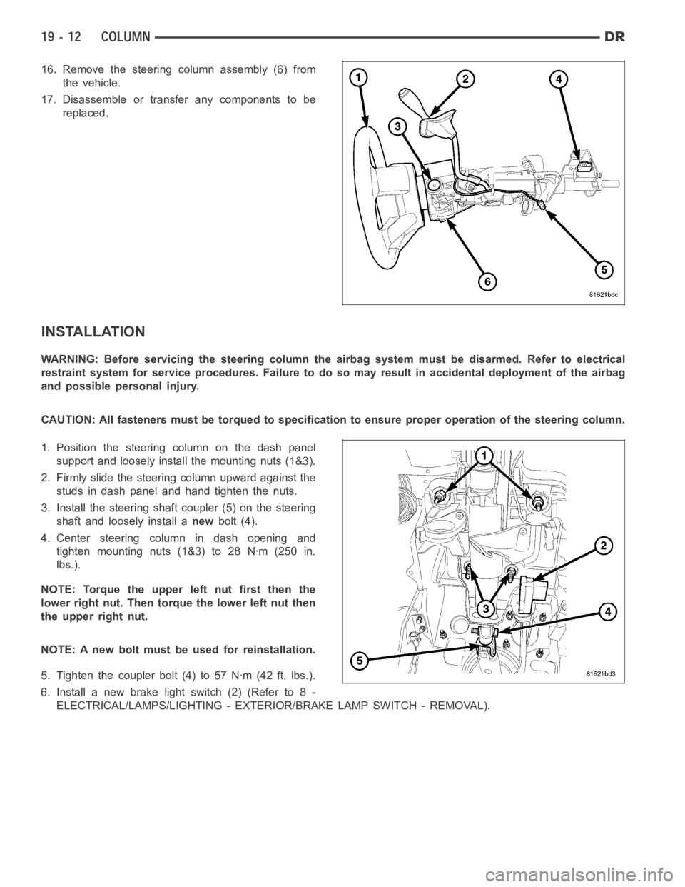
16. Remove the steering column assembly (6) from
the vehicle.
17. Disassemble or transfer any components to be
replaced.
INSTALLATION
WARNING: Before servicing the steering column the airbag system must be disarmed. Refer to electrical
restraint system for service procedures. Failure to do so may result in accidental deployment of the airbag
and possible personal injury.
CAUTION: All fasteners must be torqued to specification to ensure proper operation of the steering column.
1. Position the steering column on the dash panel
support and loosely install the mounting nuts (1&3).
2. Firmly slide the steering column upward against the
studs in dash panel and hand tighten the nuts.
3. Install the steering shaft coupler (5) on the steering
shaft and loosely install anewbolt (4).
4. Center steering column in dash opening and
tighten mounting nuts (1&3) to 28 Nꞏm (250 in.
lbs.).
NOTE: Torque the upper left nut first then the
lower right nut. Then torque the lower left nut then
the upper right nut.
NOTE: A new bolt must be used for reinstallation.
5. Tighten the coupler bolt (4) to 57 Nꞏm (42 ft. lbs.).
6. Install a new brake light switch (2) (Refer to 8 -
ELECTRICAL/LAMPS/LIGHTING - EXTERIOR/BRAKE LAMP SWITCH - REMOVAL).