2006 DODGE RAM SRT-10 service
[x] Cancel search: servicePage 2126 of 5267
BEARINGS-CRANKSHAFT MAIN
DESCRIPTION
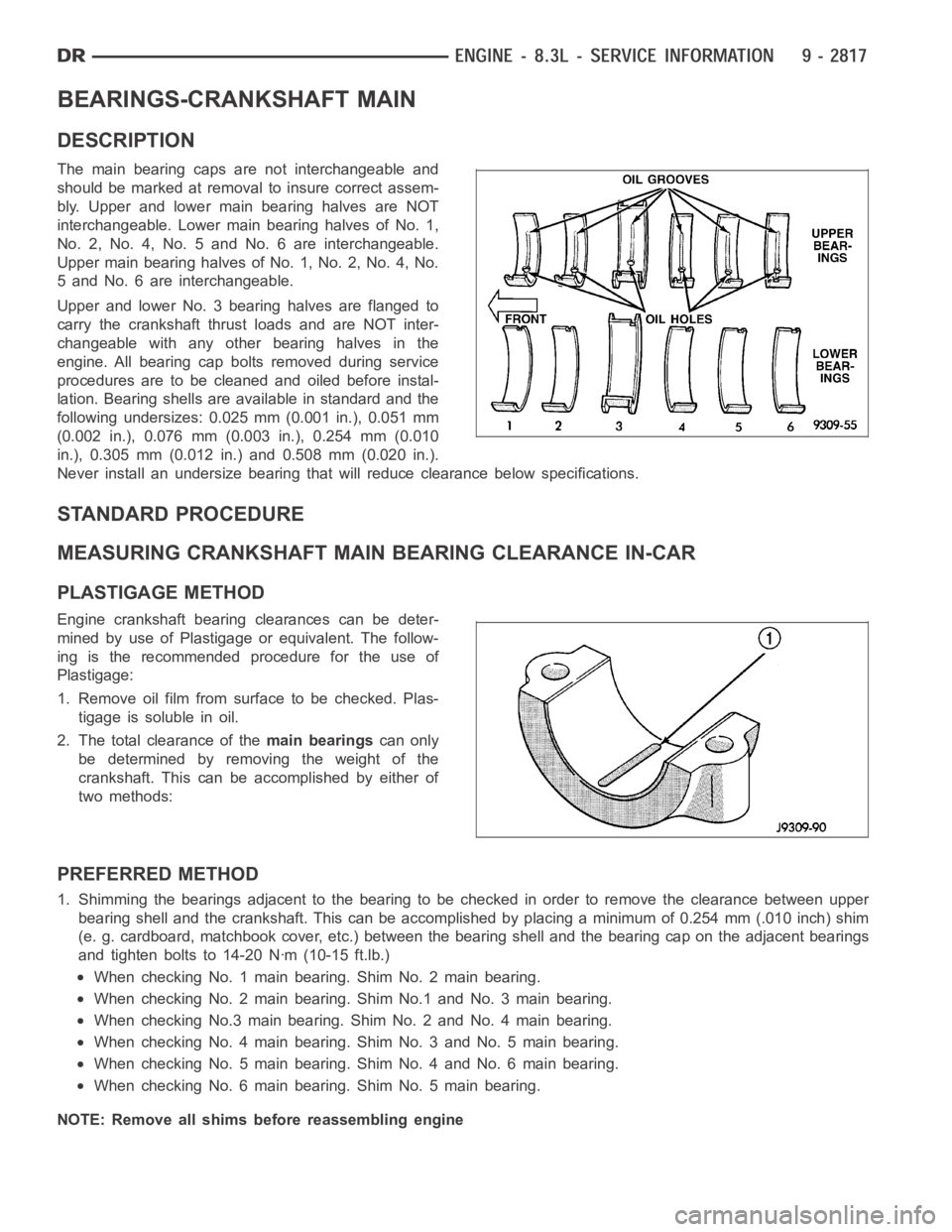
The main bearing caps are not interchangeable and
should be marked at removalto insure correct assem-
bly. Upper and lower main bearing halves are NOT
interchangeable. Lower main bearing halves of No. 1,
No. 2, No. 4, No. 5 and No. 6 are interchangeable.
Upper main bearing halves of No. 1, No. 2, No. 4, No.
5 and No. 6 are interchangeable.
Upper and lower No. 3 bearing halves are flanged to
carry the crankshaft thrust loads and are NOT inter-
changeable with any other bearing halves in the
engine. All bearing cap bolts removed during service
procedures are to be cleaned and oiled before instal-
lation. Bearing shells are available in standard and the
following undersizes: 0.025 mm (0.001 in.), 0.051 mm
(0.002 in.), 0.076 mm (0.003 in.), 0.254 mm (0.010
in.), 0.305 mm (0.012 in.) and 0.508 mm (0.020 in.).
Never install an undersize bearing that will reduce clearance below specifications.
STANDARD PROCEDURE
MEASURING CRANKSHAFT MAIN BEARING CLEARANCE IN-CAR
PLASTIGAGE METHOD
Engine crankshaft bearing clearances can be deter-
mined by use of Plastigage or equivalent. The follow-
ing is the recommended procedure for the use of
Plastigage:
1. Remove oil film from surface to be checked. Plas-
tigage is soluble in oil.
2. The total clearance of themain bearingscan only
be determined by removing the weight of the
crankshaft. This can be accomplished by either of
two methods:
PREFERRED METHOD
1. Shimming the bearings adjacent to the bearing to be checked in order to remove the clearance between upper
bearing shell and the crankshaft. Thiscanbeaccomplishedbyplacingaminimum of 0.254 mm (.010 inch) shim
(e. g. cardboard, matchbook cover, etc.) between the bearing shell and thebearing cap on the adjacent bearings
and tighten bolts to 14-20 Nꞏm (10-15 ft.lb.)
When checking No. 1 main bearing. Shim No. 2 main bearing.
When checking No. 2 main bearing. Shim No.1 and No. 3 main bearing.
When checking No.3 main bearing. Shim No. 2 and No. 4 main bearing.
When checking No. 4 main bearing. Shim No. 3 and No. 5 main bearing.
When checking No. 5 main bearing. Shim No. 4 and No. 6 main bearing.
When checking No. 6 main bearing. Shim No. 5 main bearing.
NOTE: Remove all shims before reassembling engine
Page 2143 of 5267
CONVERTER-CATALYTIC
DESCRIPTION
WARNING: THE NORMAL OPERATING TEMPERATURE OF THE EXHAUST SYSTEM IS VERY HIGH. THERE-
FORE, NEVER WORK AROUND OR ATTEMPT TO SERVICE ANY PART OF THE EXHAUST SYSTEMUNTIL IT
IS COOLED. SPECIAL CARE SHOULD BE TAKEN WHEN WORKING NEAR THE CATALYTIC CONVERTER.
THE TEMPERATURE OF THE CONVERTER RISES TO A HIGH LEVEL AFTER A SHORT PERIOD OFENGINE
OPERATION TIME.
CAUTION: DO NOT remove spark plug wires from plugs or by any other means short out cylinders. Failure
of the catalytic converter can occur due to a temperature increase caused by unburned fuel passing
through the converter.
The stainless steel catalytic converter body is designed to last the life of the vehicle. Excessive heat can result in
bulging or other distortion, but excessive heat will not be the fault of theconverter. If unburned fuel enters the con-
verter, overheating may occur. If a converter is heat-damaged, correct the cause of the damage at the same time
the converter is replaced. Also, inspect all other components of the exhaust system for heat damage.
Unleaded gasoline must be used to avoid contaminating the catalyst core.
50 State emission vehicles incorporate two mini catalytic converters located after the exhaust manifolds and before
the inline catalytic converter.
OPERATION
The catalytic converter captures and burns any unburned fuel mixture exiting the combustion chambers during the
exhaust stroke of the engine. This process aids in reducing emissions output.
REMOVAL
3.7L/4.7L ENGINE
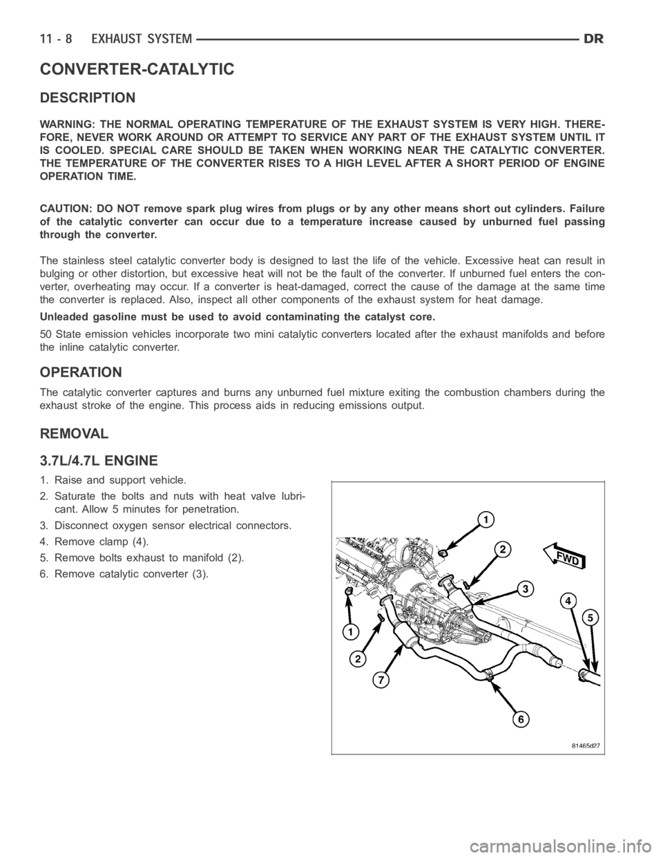
1. Raise and support vehicle.
2. Saturate the bolts and nuts with heat valve lubri-
cant. Allow 5 minutes for penetration.
3. Disconnect oxygen sensor electrical connectors.
4. Remove clamp (4).
5. Remove bolts exhaust to manifold (2).
6. Remove catalytic converter (3).
Page 2164 of 5267
REMOVAL
TURBOCHARGER
1. Disconnect the battery negative cables.
2. Raise vehicle on hoist.
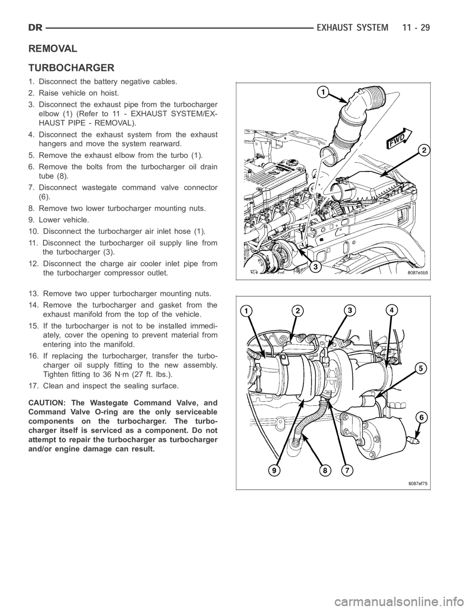
3. Disconnect the exhaust pipe from the turbocharger
elbow (1) (Refer to 11 - EXHAUST SYSTEM/EX-
HAUST PIPE - REMOVAL).
4. Disconnect the exhaust system from the exhaust
hangers and move the system rearward.
5. Remove the exhaust elbow from the turbo (1).
6. Remove the bolts from the turbocharger oil drain
tube (8).
7. Disconnect wastegate command valve connector
(6).
8. Remove two lower turbocharger mounting nuts.
9. Lower vehicle.
10. Disconnect the turbocharger air inlet hose (1).
11. Disconnect the turbocharger oil supply line from
the turbocharger (3).
12. Disconnect the charge air cooler inlet pipe from
the turbocharger compressor outlet.
13. Remove two upper turbocharger mounting nuts.
14. Remove the turbocharger and gasket from the
exhaust manifold from the top of the vehicle.
15. If the turbocharger is not to be installed immedi-
ately, cover the opening to prevent material from
entering into the manifold.
16. If replacing the turbocharger, transfer the turbo-
charger oil supply fitting to the new assembly.
Tighten fitting to 36 Nꞏm (27 ft. lbs.).
17. Clean and inspect the sealing surface.
CAUTION: The Wastegate Command Valve, and
Command Valve O-ring are the only serviceable
components on the turbocharger. The turbo-
charger itself is serviced as a component. Do not
attempt to repair the turbocharger as turbocharger
and/or engine damage can result.
Page 2171 of 5267
CLEANING
CAUTION: Do not use caustic cleaners to clean the charge air cooler. Damageto the charge air cooler will
result.
NOTE: If internal debris cannot be removed from the cooler, the charge air cooler MUST be replaced.
1. If the engine experiences a turbocharger failure or any other situationwhere oil or debris get into the charge air
cooler, the charge air cooler must be cleaned internally.
2. Position the charge air cooler so the inlet and outlet tubes are vertical.
3. Flush the cooler internally with solvent in the direction opposite of normal air flow.
4. Shake the cooler and lightly tap on the end tanks with a rubber mallet to dislodge trapped debris.
5. Continue flushing until all debris or oil are removed.
6. Rinse the cooler with hot soapy water to remove any remaining solvent.
7. Rinse thoroughly with clean water and blow dry with compressed air.
INSPECTION
Visually inspect the charge air cooler for cracks, holes, or damage. Inspect the tubes, fins, and welds for tears,
breaks, or other damage. Replace the charge air cooler if damage is found.
Pressure test the charge air cooler, using Charge Air Cooler Tester Kit No.3824556. This kit is available through
Cummins
Service Products. Instructions are provided with the kit.
INSTALLATION
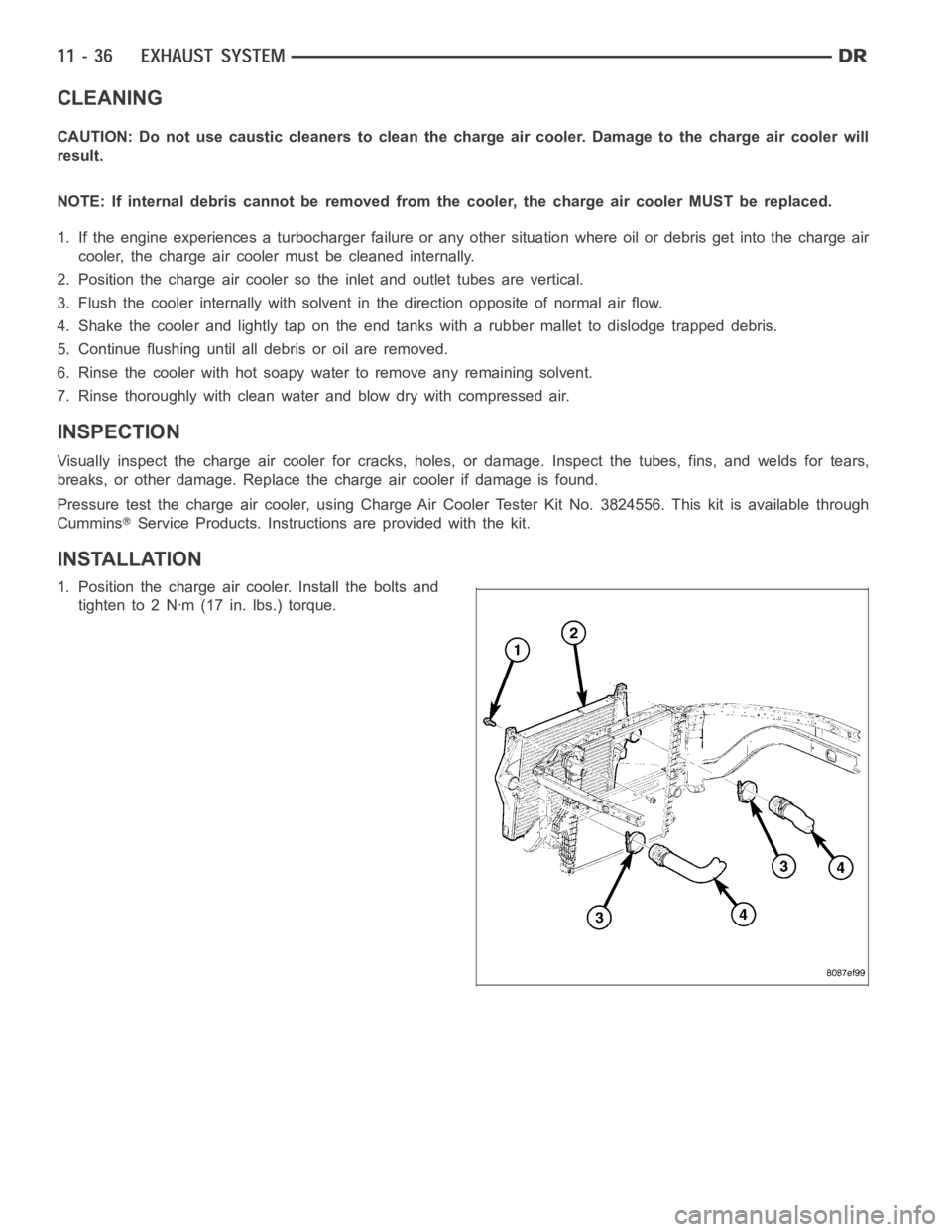
1. Position the charge air cooler. Install the bolts and
tighten to 2 Nꞏm (17 in. lbs.) torque.
Page 2191 of 5267
STANDARD PROCEDURE
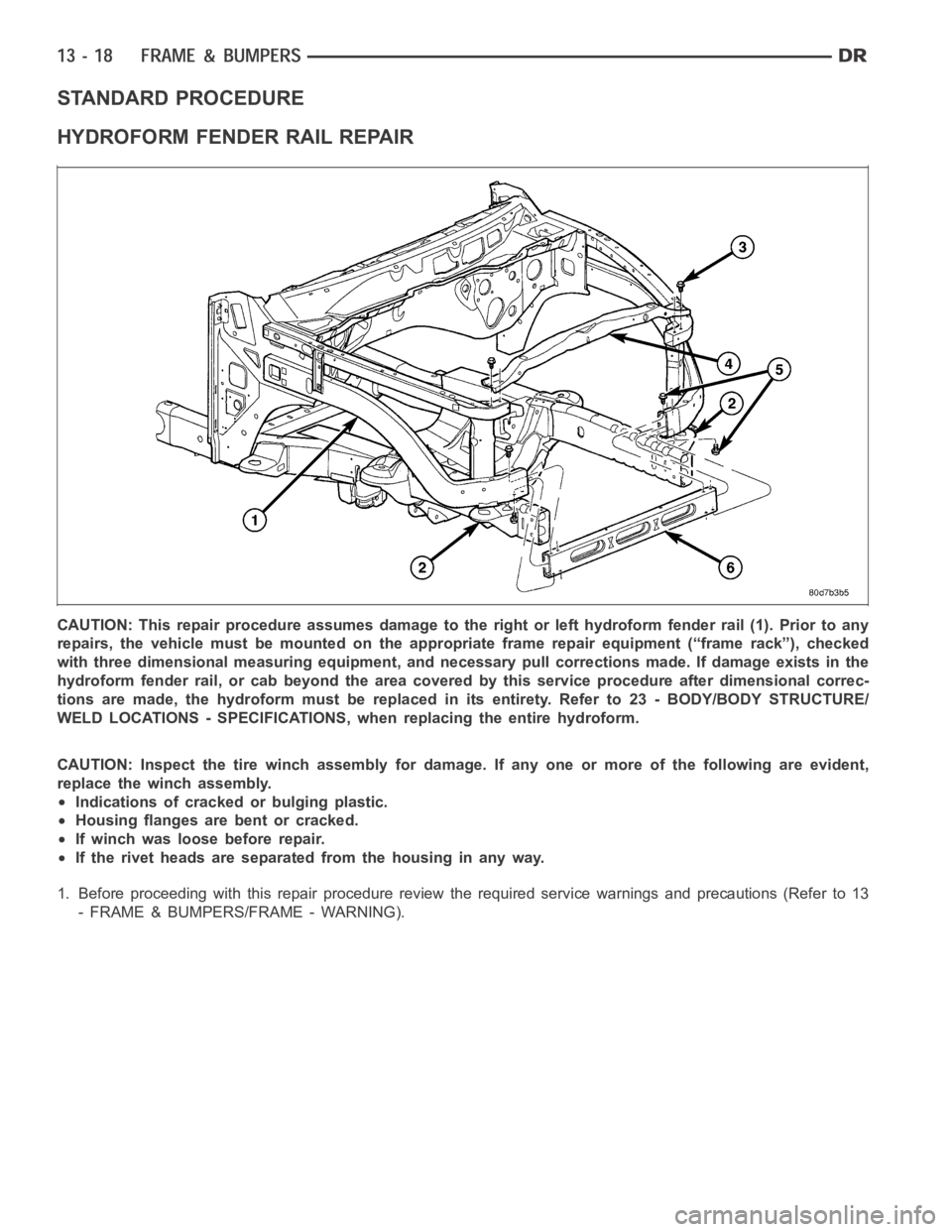
HYDROFORM FENDER RAIL REPAIR
CAUTION: This repair procedure assumes damage to the right or left hydroform fender rail (1). Prior to any
repairs, the vehicle must be mounted on the appropriate frame repair equipment (“frame rack”), checked
with three dimensional measuring equipment, and necessary pull corrections made. If damage exists in the
hydroform fender rail, or cab beyond the area covered by this service procedure after dimensional correc-
tions are made, the hydroform must be replaced in its entirety. Refer to 23 -BODY/BODY STRUCTURE/
WELD LOCATIONS - SPECIFICATIONS, when replacing the entire hydroform.
CAUTION: Inspect the tire winch assembly for damage. If any one or more of thefollowingareevident,
replace the winch assembly.
Indications of cracked or bulging plastic.
Housing flanges are bent or cracked.
If winch was loose before repair.
If the rivet heads are separated from the housing in any way.
1. Before proceeding with this repair procedure review the required service warnings and precautions (Refer to 13
- FRAME & BUMPERS/FRAME - WARNING).
Page 2196 of 5267
15. Using a reciprocating saw or equivalent, cut the fender rail and shotgun at a straight and square section of the
hydroform and remove.
16. Smooth and square the cut edges.
17. Using the damaged structure as a reference cut the service part at the same location as the first cut. Smooth
and square the cut edges.
NOTE: The repair structure should butt up to the remaining structure and provide the same overall vehicle
geometry.
18. Fabricate 51 mm (2.0 in.) long repair inserts using scrap from the old structure or the replacement part. It will
be necessary to split the inserts on each of their four sides to fit into the hydroform.
19. Remove any paint or e-coat from the inserts and also to the interior and exterior of the hydroforms.
20. Cut plug weld holes as described below.
On the upper rail, cut one 13 mm (0.5 in.) hole on each side of the rail, 25 mm (1.0 in.) from the butt joint of
the tubes.
On the lower rail, cut one 13 mm (0.5 in.) hole on the top and bottom sides of therail25mm(1.0in.)fromthe
butt joint of the tube.
On the lower rail, cut two 13 mm (0.5 in.) holes on the inner and outer sides oftherail25mm(1.0in.)from
the butt joint of the tube.
CAUTION: Shield the surrounding area and components from exposure to the welding spatter and heat.
21. Install the insert 1” into the replacement part and tack into place witha weld. (Refer to 13 - FRAME &
BUMPERS/FRAME - SPECIFICATIONS - WELDING)
22. Insert the service part into place and using the appropriate measuringequipment, verify the front end sheet
metal bracket’s location in all three (X,Y, and Z) planes of space.
23. Complete all 360° plug welds.
NOTE: Before the final welding, use three dimensional measuring equipment to ensure the part is in the
correct location. Verify that tap plate extrusion at the bottom of the vertical post lines up with the isolator
and hole in the frame perch mount. Also ensure the lower radiator closure tube is bolted into the forward
shotgun ends.
24. Complete welding by making a 360° butt weld around the fender rails.
25. Metal finish the exposed welds on the hydroforms.
26. Dress the welded area and apply corrosion resistant coatings inside and out.
a. Inside the rail, inject a creeping wax based rust inhibitor compound to the inside of the hydroforms ensuring
100% coverage including the mating face between the fender rail sections and insert such that corrosion
protection is restored in the internal cavity.
b. Apply a durable top coat to the outside of the repair area.
Page 2200 of 5267
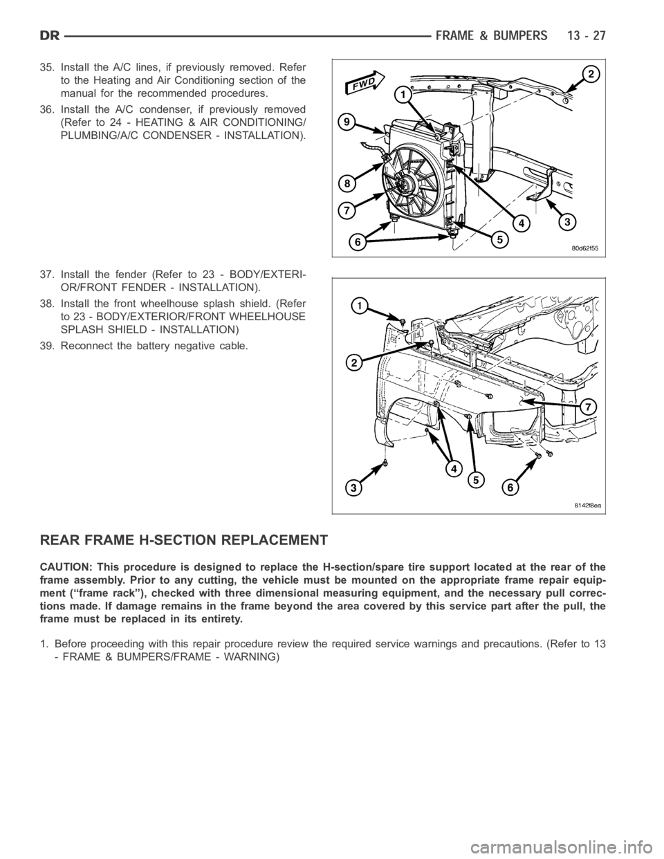
35. Install the A/C lines, if previously removed. Refer
to the Heating and Air Conditioning section of the
manual for the recommended procedures.
36. Install the A/C condenser, if previously removed
(Refer to 24 - HEATING & AIR CONDITIONING/
PLUMBING/A/C CONDENSER - INSTALLATION).
37. Install the fender (Refer to 23 - BODY/EXTERI-
OR/FRONT FENDER - INSTALLATION).
38. Install the front wheelhouse splash shield. (Refer
to 23 - BODY/EXTERIOR/FRONT WHEELHOUSE
SPLASH SHIELD - INSTALLATION)
39. Reconnect the battery negative cable.
REAR FRAME H-SECTION REPLACEMENT
CAUTION: This procedure is designed to replace the H-section/spare tire support located at the rear of the
frame assembly. Prior to any cutting, the vehicle must be mounted on the appropriate frame repair equip-
ment (“frame rack”), checked with three dimensional measuring equipment, and the necessary pull correc-
tions made. If damage remains in the frame beyond the area covered by this service part after the pull, the
frame must be replaced in its entirety.
1. Before proceeding with this repair procedure review the required service warnings and precautions. (Refer to 13
- FRAME & BUMPERS/FRAME - WARNING)
Page 2246 of 5267
FUEL FILTER/PRESSURE REGULATOR
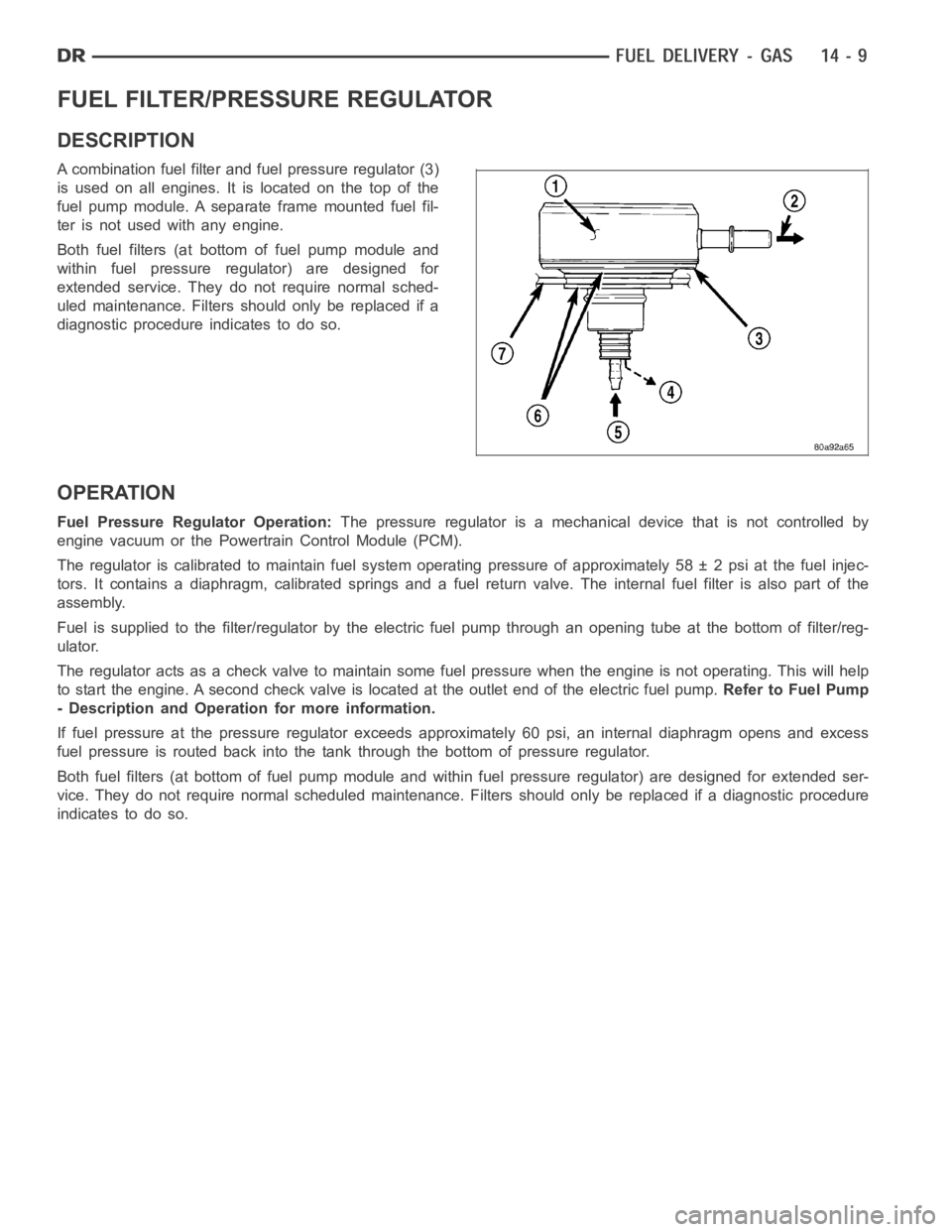
DESCRIPTION
A combination fuel filter and fuel pressure regulator (3)
is used on all engines. It is located on the top of the
fuel pump module. A separate frame mounted fuel fil-
ter is not used with any engine.
Both fuel filters (at bottom of fuel pump module and
within fuel pressure regulator) are designed for
extended service. They do not require normal sched-
uled maintenance. Filters should only be replaced if a
diagnostic procedure indicates to do so.
OPERATION
Fuel Pressure Regulator Operation:The pressure regulator is a mechanical device that is not controlled by
engine vacuum or the Powertrain Control Module (PCM).
The regulator is calibrated to maintain fuel system operating pressure ofapproximately 58 ± 2 psi at the fuel injec-
tors. It contains a diaphragm, calibrated springs and a fuel return valve.The internal fuel filter is also part of the
assembly.
Fuel is supplied to the filter/regulator by the electric fuel pump throughan opening tube at the bottom of filter/reg-
ulator.
The regulator acts as a check valve to maintain some fuel pressure when the engine is not operating. This will help
to start the engine. A second check valve is located at the outlet end of the electric fuel pump.Refer to Fuel Pump
- Description and Operation for more information.
If fuel pressure at the pressure regulator exceeds approximately 60 psi, an internal diaphragm opens and excess
fuel pressure is routed back into the tank through the bottom of pressure regulator.
Both fuel filters (at bottom of fuel pump module and within fuel pressure regulator) are designed for extended ser-
vice. They do not require normal scheduled maintenance. Filters should only be replaced if a diagnostic procedure
indicates to do so.