Page 2421 of 5267
REMOVAL
SERVICE PRECAUTIONS
NOTE: The steering column on vehicles equipped with an automatic transmission is not equipped with an
internal locking shaft with the ignition cylinder. Alternative methods of locking the steering wheel for ser-
vice will have to be used.
To service the steering wheel, switches or airbag, Refer to Electrical Restraints and follow all WARNINGS and CAU-
TIONS.
WARNING: The airbag system is a sensitive, complex electro-mechanical unit. Before attempting to diag-
nose, remove or install the airbag system components you must first disconnect and isolate the battery
negative (ground) cable. Then wait two minutes for the system capacitor todischarge. Failure to do so
could result in accidental deployment of the airbag and possible personalinjury. The fasteners, screws, and
bolts, originally used for the airbag components, have special coatings and are specifically designed for the
airbag system. They must never be replaced with any substitutes. Anytime anew fastener is needed,
replace with the correct fasteners provided in the service package or fasteners listed in the parts books.
CAUTION: Do not hammer on steering column shaft. This may cause damage to the shaft or bearing.
CAUTION: Do not attempt to remove the pivot bolts to disassemble the tilting mechanism.
The ignition key must be in the key cylinder for cylinder removal. The key cylinder must be removed first before
removing ignition switch.
1. Remove the negative (ground) cable from the battery.
2. Disable the airbag, (Refer to 8 - ELECTRICAL/RESTRAINTS/DRIVER AIRBAG- REMOVAL).
3. Remove the kneeblocker and steering column reinforcement panel.
4. Remove the lower and upper shrouds.
5. Remove key cylinder. (Refer to 19 - STEERING/COLUMN/LOCK CYLINDER HOUSING - REMOVAL).
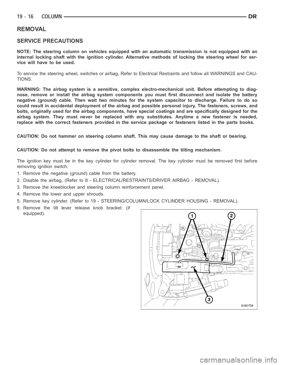
6. Remove the tilt lever release knob bracket. (if
equipped).
Page 2437 of 5267
UPPER STEERING COUPLING
REMOVAL
1. Disconnect the negative battery cable.
NOTE: The steering column on vehicles with an automatic transmission may not be equipped with an inter-
nal locking shaft that allows the ignition key cylinder to be locked with the key. Alternative methods of lock-
ing the steering wheel for service will have to be used.
2. Lock the steering wheel with the tire in the straight position.
3. Remove and discard the lower pinch bolt.
4. Lower the steering coupler shaft from the column.
5. Remove the upper steering coupling shaft (2) seal
by pushing in the four tags (1) securing it to the
panel.
6. Remove and discard the lower coupler pinch bolt
(1) from the lower steering coupling shaft (1).
7. Remove the upper steering coupling shaft (3) from
the vehicle.
Page 2439 of 5267
LOWER STEERING COUPLING
REMOVAL
ALLLD&HDEXCEPT4X4HD
1. Disconnect the negative battery cable.
2. Raise and support the vehicle.
NOTE: The steering column on vehicles with an automatic transmission may not be equipped with an inter-
nal locking shaft that allows the ignition key cylinder to be locked with the key. Alternative methods of lock-
ing the steering wheel for service will have to be used.
3. Lock the steering wheel with the tire in the straight position.
4. Remove the left front tire and wheel assembly.
5. Mark both coupler connections for proper installation.
6. Remove and discard the upper coupler pinch bolt.
7. Remove and discard the lower coupler pinch bolt.
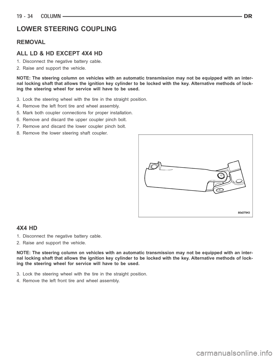
8. Remove the lower steering shaft coupler.
4X4 HD
1. Disconnect the negative battery cable.
2. Raise and support the vehicle.
NOTE: The steering column on vehicles with an automatic transmission may not be equipped with an inter-
nal locking shaft that allows the ignition key cylinder to be locked with the key. Alternative methods of lock-
ing the steering wheel for service will have to be used.
3. Lock the steering wheel with the tire in the straight position.
4. Remove the left front tire and wheel assembly.
Page 2444 of 5267
GEAR - INDEPENDENT FRONT SUSPENSION
DESCRIPTION
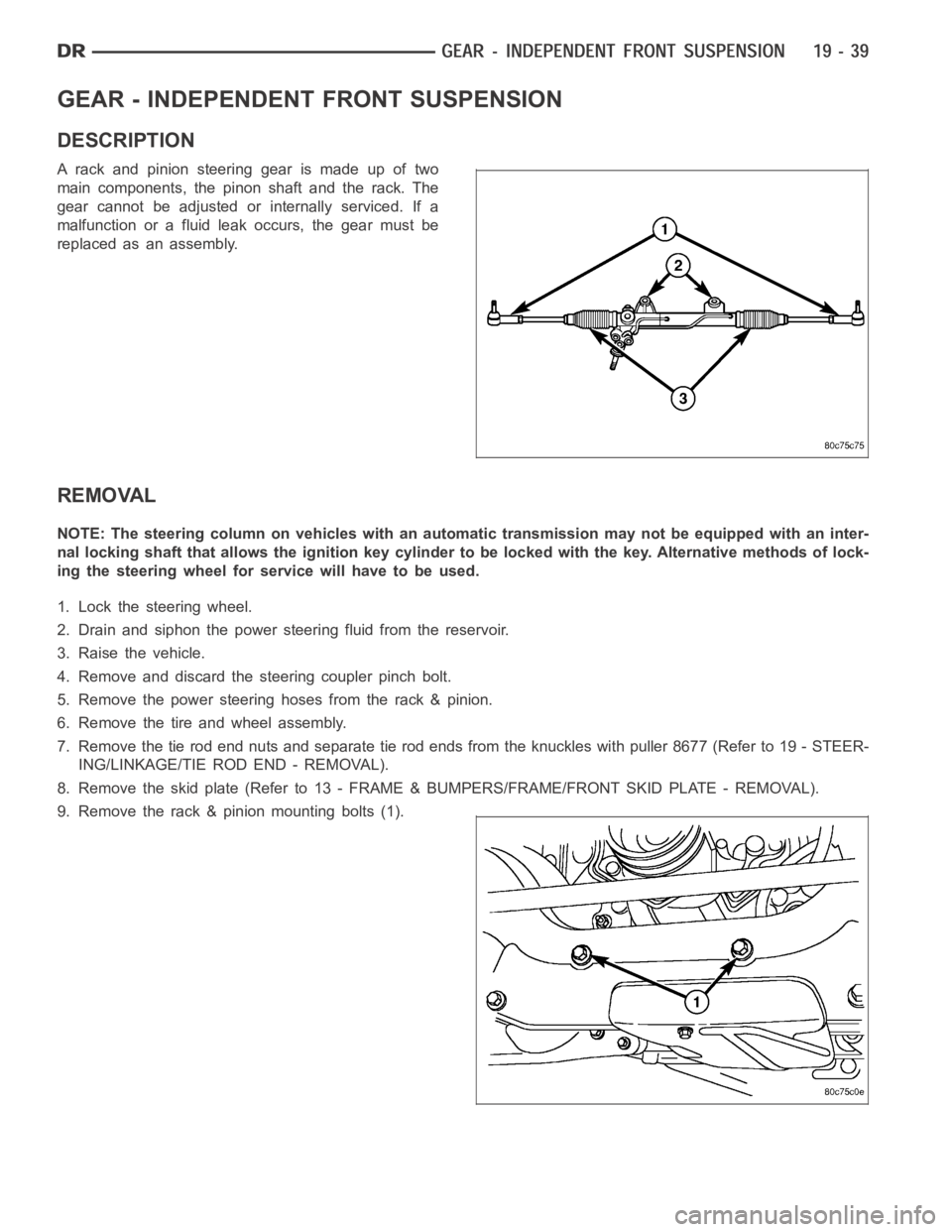
A rack and pinion steering gear is made up of two
main components, the pinon shaft and the rack. The
gear cannot be adjusted or internally serviced. If a
malfunction or a fluid leak occurs, the gear must be
replaced as an assembly.
REMOVAL
NOTE: The steering column on vehicles with an automatic transmission may not be equipped with an inter-
nal locking shaft that allows the ignition key cylinder to be locked with the key. Alternative methods of lock-
ing the steering wheel for service will have to be used.
1. Lock the steering wheel.
2. Drain and siphon the power steering fluid from the reservoir.
3. Raise the vehicle.
4. Remove and discard the steering coupler pinch bolt.
5. Remove the power steering hoses from the rack & pinion.
6. Remove the tire and wheel assembly.
7. Remove the tie rod end nuts and separate tie rod ends from the knuckles withpuller8677(Referto19-STEER-
ING/LINKAGE/TIE ROD END - REMOVAL).
8. Remove the skid plate (Refer to 13 - FRAME & BUMPERS/FRAME/FRONT SKID PLATE - REMOVAL).
9. Remove the rack & pinion mounting bolts (1).
Page 2449 of 5267
GEAR - LINK/COIL
DESCRIPTION
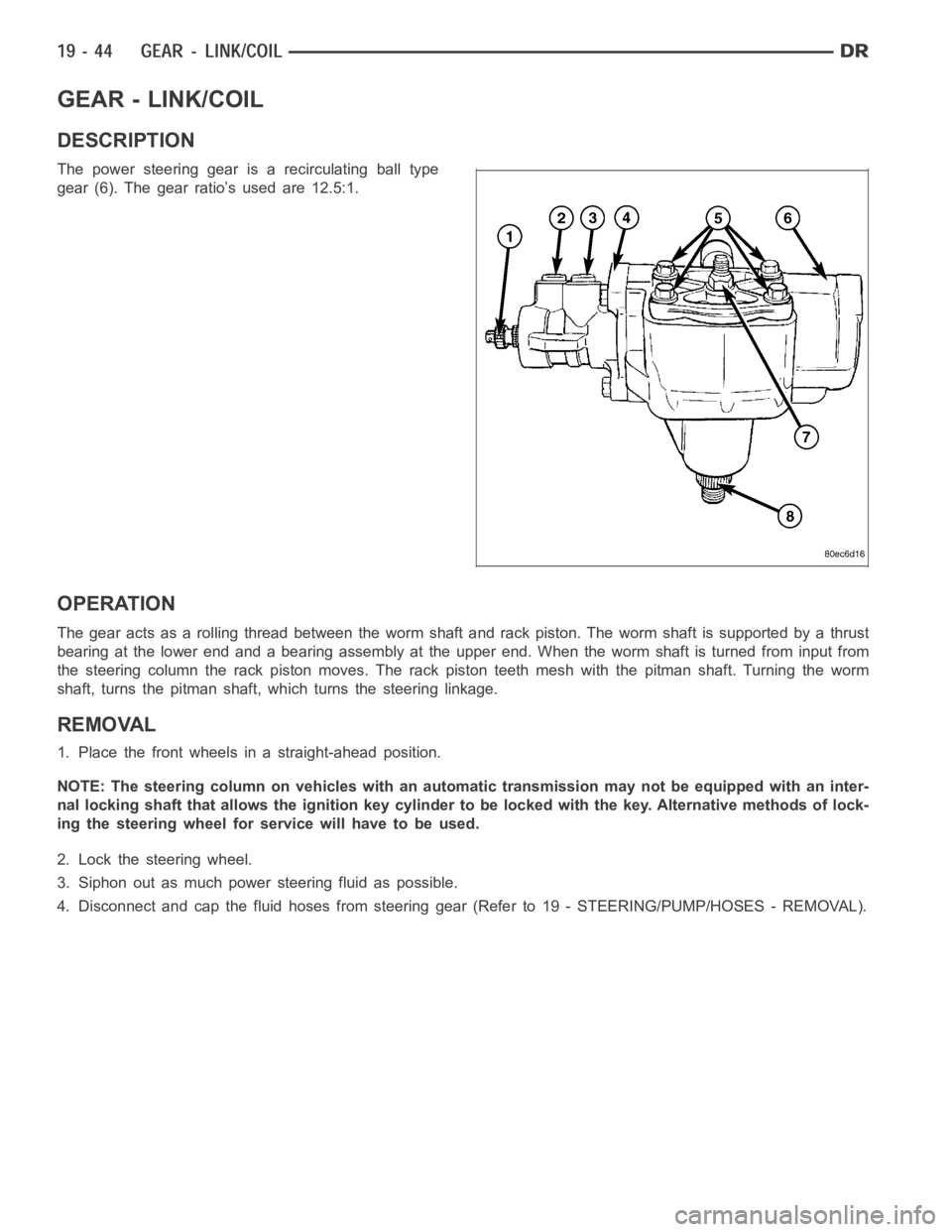
The power steering gear is a recirculating ball type
gear (6). The gear ratio’s used are 12.5:1.
OPERATION
The gear acts as a rolling thread between the worm shaft and rack piston. Theworm shaft is supported by a thrust
bearing at the lower end and a bearing assembly at the upper end. When the worm shaft is turned from input from
the steering column the rack piston moves. The rack piston teeth mesh with the pitman shaft. Turning the worm
shaft, turns the pitman shaft, which turns the steering linkage.
REMOVAL
1. Place the front wheels in a straight-ahead position.
NOTE: The steering column on vehicles with an automatic transmission may not be equipped with an inter-
nal locking shaft that allows the ignition key cylinder to be locked with the key. Alternative methods of lock-
ing the steering wheel for service will have to be used.
2. Lock the steering wheel.
3. Siphon out as much power steering fluid as possible.
4. Disconnect and cap the fluid hoses from steering gear (Refer to 19 - STEERING/PUMP/HOSES - REMOVAL).
Page 2472 of 5267
LINKAGE - LINK/COIL
DESCRIPTION
Thesteeringlinkageiscomprisedofatierodend(5),
tie rod, drag link (7), steering damper (9) and pitman
arm (2).
CAUTION: If any steering components are
replaced or serviced an alignment must be per-
formed.
NOTE: To avoid damaging ball stud seals, use
Puller C-3894–A (3) or an appropriate puller to
remove tie rod ends (5).
STANDARD PROCEDURE
LUBRICATION
Periodic lubrication of the steering system components is required. Refer to Lubrication And Maintenance for the
recommended maintenance schedule.
The following components must be lubricated:
Tie rod
Tie rod end
Drag link
Page 2482 of 5267
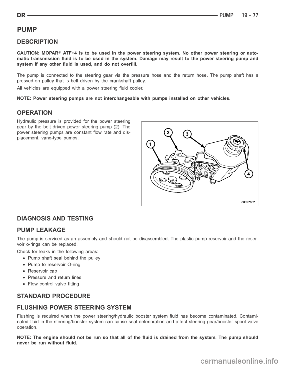
PUMP
DESCRIPTION
CAUTION: MOPARATF+4 is to be used in the power steering system. No other power steering or auto-
matic transmission fluid is to be used in the system. Damage may result to the power steering pump and
system if any other fluid is used, and do not overfill.
The pump is connected to the steering gear via the pressure hose and the return hose. The pump shaft has a
pressed-on pulley that is belt driven by the crankshaft pulley.
All vehicles are equipped with a power steering fluid cooler.
NOTE: Power steering pumps are not interchangeable with pumps installed on other vehicles.
OPERATION
Hydraulic pressure is provided for the power steering
gear by the belt driven power steering pump (2). The
power steering pumps are constant flow rate and dis-
placement, vane-type pumps.
DIAGNOSIS AND TESTING
PUMP LEAKAGE
The pump is serviced as an assembly and should not be disassembled. The plastic pump reservoir and the reser-
voir o-rings can be replaced.
Check for leaks in the following areas:
Pump shaft seal behind the pulley
Pump to reservoir O-ring
Reservoir cap
Pressure and return lines
Flow control valve fitting
STANDARD PROCEDURE
FLUSHING POWER STEERING SYSTEM
Flushing is required when the power steering/hydraulic booster system fluid has become contaminated. Contami-
nated fluid in the steering/booster system can cause seal deterioration and affect steering gear/booster spool valve
operation.
NOTE: The engine should not be run so that all of the fluid is drained from thesystem. The pump should
never be run without fluid.
Page 2522 of 5267
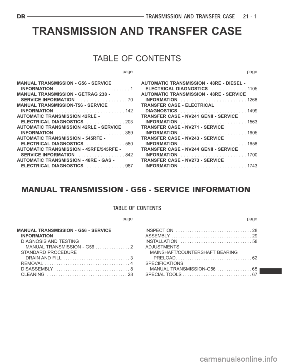
TRANSMISSION AND TRANSFER CASE
TABLE OF CONTENTS
page page
MANUAL TRANSMISSION - G56 - SERVICE
INFORMATION...........................1
MANUAL TRANSMISSION - GETRAG 238 -
SERVICE INFORMATION..................70
MANUAL TRANSMISSION-T56 - SERVICE
INFORMATION.........................142
AUTOMATIC TRANSMISSION 42RLE -
ELECTRICAL DIAGNOSTICS..............203
AUTOMATIC TRANSMISSION 42RLE - SERVICE
INFORMATION.........................389
AUTOMATIC TRANSMISSION - 545RFE -
ELECTRICAL DIAGNOSTICS..............580
AUTOMATIC TRANSMISSION - 45RFE/545RFE -
SERVICE INFORMATION.................842
AUTOMATIC TRANSMISSION - 48RE - GAS -
ELECTRICAL DIAGNOSTICS..............987AUTOMATIC TRANSMISSION - 48RE - DIESEL -
ELECTRICAL DIAGNOSTICS.............1105
AUTOMATIC TRANSMISSION - 48RE - SERVICE
INFORMATION........................1266
TRANSFER CASE - ELECTRICAL
DIAGNOSTICS........................1499
TRANSFER CASE - NV241 GENII - SERVICE
INFORMATION........................1563
TRANSFER CASE - NV271 - SERVICE
INFORMATION........................1605
TRANSFER CASE - NV243 - SERVICE
INFORMATION........................1656
TRANSFER CASE - NV244 GENII - SERVICE
INFORMATION........................1700
TRANSFER CASE - NV273 - SERVICE
INFORMATION........................1743
page page
MANUAL TRANSMISSION - G56 - SERVICE
INFORMATION
DIAGNOSIS AND TESTING
MANUAL TRANSMISSION - G56 ............... 2
STANDARD PROCEDURE
DRAIN AND FILL ............................. 3
REMOVAL ..................................... 4
DISASSEMBLY ................................ 8
CLEANING ................................... 28INSPECTION ................................. 28
ASSEMBLY ................................... 29
INSTALLATION ............................... 58
ADJUSTMENTS
MAINSHAFT/COUNTERSHAFT BEARING
PRELOAD.................................. 62
SPECIFICATIONS
MANUAL TRANSMISSION-G56 ............... 65
SPECIAL TOOLS .............................. 67