2006 DODGE RAM SRT-10 service
[x] Cancel search: servicePage 1487 of 5267
page page
ENGINE - 3.7L - SERVICE INFORMATION
DESCRIPTION ............................. 2180
DIAGNOSIS AND TESTING
DIAGNOSIS AND TESTING - ENGINE
DIAGNOSIS - INTRODUCTION............. 2180
DIAGNOSIS AND TESTING - ENGINE
DIAGNOSIS - PERFORMANCE............. 2181
DIAGNOSIS AND TESTING - ENGINE
DIAGNOSIS - MECHANICAL............... 2183
DIAGNOSIS AND TESTING - ENGINE
DIAGNOSIS - LUBRICATION............... 2183
DIAGNOSIS AND TESTING - CYLINDER
COMPRESSION PRESSURE............... 2185
DIAGNOSIS AND TESTING - CYLINDER
COMBUSTION PRESSURE LEAKAGE...... 2185
STANDARD PROCEDURE
STANDARD PROCEDURE - REPAIR
DAMAGED OR WORN THREADS.......... 2186
STANDARD PROCEDURE - FORM-IN-
PLACE GASKETS AND SEALERS.......... 2186
STANDARD PROCEDURE - ENGINE
GASKET SURFACE PREPARATION........ 2187
REMOVAL ................................. 2188
INSTALLATION ............................. 2192
SPECIFICATIONS
SPECIFICATIONS - 3.7L ENGINE .......... 2195
TORQUE ................................. 2199
SPECIAL TOOLS ........................... 2202
ELEMENT - AIR CLEANER
REMOVAL ................................. 2206
INSTALLATION ............................. 2207
HEAD-CYLINDER-LEFT
DIAGNOSIS AND TESTING - CYLINDER HEAD
GASKET . . ............................... 2208
REMOVAL ................................. 2208
INSTALLATION ............................. 2211
CAMSHAFT
DESCRIPTION ............................. 2214
REMOVAL ................................. 2214
INSTALLATION ............................. 2215
COVER-CYLINDER HEAD
DESCRIPTION ............................. 2217
REMOVAL ................................. 2217
INSTALLATION ............................. 2218
VALVES & SEATS - INTAKE/EXHAUST
DESCRIPTION ............................. 2219
STANDARD PROCEDURE - REFACING ....... 2219
REMOVAL ................................. 2220
INSTALLATION ............................. 2221
ARM-VALVE ROCKER
DESCRIPTION ............................. 2222REMOVAL ................................. 2222
INSTALLATION ............................. 2222
SEALS-VALVE GUIDE
DESCRIPTION ............................. 2224
SPRINGS-VALVE
DESCRIPTION ............................. 2225
REMOVAL ................................. 2225
INSTALLATION ............................. 2225
HEAD-CYLINDER-RIGHT
DIAGNOSIS AND TESTING - HYDRAULIC
LASH ADJUSTER ......................... 2227
REMOVAL
REMOVAL RIGHT CYLINDER HEAD ........ 2227
INSTALLATION
INSTALLATION RIGHT CYLINDER HEAD . . . 2230
CAMSHAFT
DESCRIPTION ............................. 2234
REMOVAL ................................. 2234
INSTALLATION ............................. 2237
COVER - CYLINDER HEAD
REMOVAL ................................. 2239
INSTALLATION ............................. 2239
ROCKER ARM - VALVE
DESCRIPTION ............................. 2240
REMOVAL ................................. 2240
SEALS - VALVE GUIDE
DESCRIPTION ............................. 2241
SPRINGS - VALVE
DESCRIPTION ............................. 2242
REMOVAL ................................. 2242
INSTALLATION ............................. 2242
BLOCK-ENGINE
DESCRIPTION ............................. 2244
STANDARD PROCEDURE - CYLINDER BORE
HONING ................................. 2244
CLEANING ................................. 2244
INSPECTION............................... 2245
CRANKSHAFT
DESCRIPTION ............................. 2246
REMOVAL ................................. 2247
INSPECTION............................... 2248
INSTALLATION ............................. 2248
BEARINGS-CRANKSHAFT MAIN
STANDARD PROCEDURE
MAIN BEARING FITTING.................. 2251
SEAL-CRANKSHAFT OIL-FRONT
REMOVAL ................................. 2253
INSTALLATION ............................. 2254
SEAL-CRANKSHAFT OIL-REAR
DIAGNOSIS AND TESTING - REAR SEAL
AREA LEAKS ............................. 2255
Page 1488 of 5267
REMOVAL ................................. 2255
INSTALLATION ............................. 2256
PLATE-FLEX
REMOVAL ................................. 2257
INSTALLATION ............................. 2257
ROD-PISTON AND CONNECTING
DESCRIPTION ............................. 2258
STANDARD PROCEDURE
CONNECTING ROD BEARING FITTING .... 2258
STANDARD PROCEDURE - PISTON
FITTING.................................. 2261
REMOVAL ................................. 2262
CLEANING ................................. 2262
INSPECTION ............................... 2262
INSTALLATION ............................. 2263
RINGS-PISTON
STANDARD PROCEDURE - PISTON RING
FITTING .................................. 2265
DAMPER-CRANKSHAFT
REMOVAL ................................. 2268
INSTALLATION ............................. 2269
COVER-STRUCTURAL
DESCRIPTION ............................. 2270
OPERATION ............................... 2270
REMOVAL ................................. 2270
INSTALLATION ............................. 2270
MOUNT-FRONT
REMOVAL ................................. 2271
INSTALLATION ............................. 2273
MOUNT-REAR
REMOVAL ................................. 2275
INSTALLATION ............................. 2275
LUBRICATION
DESCRIPTION ............................. 2276
OPERATION ............................... 2276
DIAGNOSIS AND TESTING
DIAGNOSIS AND TESTING - ENGINE OIL
LEAK.................................... 2278
DIAGNOSIS AND TESTING - CHECKING
ENGINE OIL PRESSURE.................. 2279
DIAGNOSIS AND TESTING - REAR SEAL
AREA LEAKS............................. 2279
PAN-ENGINE OIL
DESCRIPTION ............................. 2280
REMOVAL ................................. 2281
CLEANING ................................. 2282
INSPECTION ............................... 2282
INSTALLATION ............................. 2282SWITCH-OIL PRESSURE
DESCRIPTION ............................. 2284
OPERATION ............................... 2284
REMOVAL ................................. 2284
INSTALLATION ............................. 2284
PUMP-ENGINE OIL
REMOVAL ................................. 2285
DISASSEMBLY . ............................ 2285
INSPECTION............................... 2285
ASSEMBLY................................ 2287
INSTALLATION ............................. 2287
FILTER-ENGINE OIL
REMOVAL ................................. 2288
INSTALLATION ............................. 2288
OIL
STANDARD PROCEDURE - ENGINE OIL
SERVICE ................................. 2289
MANIFOLD-INTAKE
DESCRIPTION ............................. 2291
DIAGNOSIS AND TESTING - INTAKE
MANIFOLD LEAKS ........................ 2291
REMOVAL ................................. 2291
INSTALLATION ............................. 2292
MANIFOLD-EXHAUST
DESCRIPTION ............................. 2294
REMOVAL ................................. 2294
INSTALLATION ............................. 2295
VALVE TIMING
DESCRIPTION ............................. 2297
OPERATION ............................... 2297
STANDARD PROCEDURE
MEASURING TIMING CHAIN WEAR ........ 2298
SERVICE PROCEDURE - TIMING
VERIFICATION........................... 2298
SHAFT-BALANCE
REMOVAL ................................. 2302
INSTALLATION ............................. 2303
SHAFT-IDLER
REMOVAL ................................. 2304
INSTALLATION ............................. 2304
COVER-TIMING
REMOVAL ................................. 2305
INSTALLATION ............................. 2306
CHAIN AND SPROCKETS-TIMING
REMOVAL ................................. 2307
INSPECTION............................... 2309
INSTALLATION ............................. 2310
Page 1489 of 5267
ENGINE - 3.7L - SERVICE INFORMATION
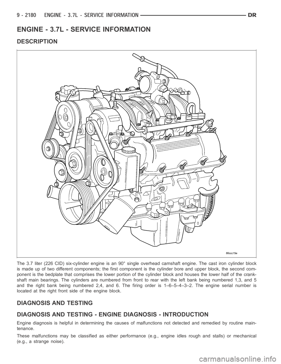
DESCRIPTION
The 3.7 liter (226 CID) six-cylinder engine is an 90° single overhead camshaft engine. The cast iron cylinder block
is made up of two different components; the first component is the cylinderbore and upper block, the second com-
ponent is the bedplate that comprises the lower portion of the cylinder block and houses the lower half of the crank-
shaft main bearings. The cylinders are numbered from front to rear with theleft bank being numbered 1,3, and 5
and the right bank being numbered 2,4, and 6. The firing order is 1–6–5–4–3–2. The engine serial number is
located at the right front side of the engine block.
DIAGNOSIS AND TESTING
DIAGNOSIS AND TESTING - ENGINE DIAGNOSIS - INTRODUCTION
Engine diagnosis is helpful in determining the causes of malfunctions notdetected and remedied by routine main-
tenance.
These malfunctions may be classified as either performance (e.g., engineidles rough and stalls) or mechanical
(e.g., a strange noise).
Page 1490 of 5267
(Refer to 9 - ENGINE - DIAGNOSIS AND TESTING) - PERFORMANCE and (Refer to 9 - ENGINE - DIAGNOSIS
AND TESTING)—MECHANICAL for possible causes and corrections of malfunctions. (Refer to 14 - FUEL SYSTEM/
FUEL DELIVERY - DIAGNOSIS AND TESTING) and (Refer to 14 - FUEL SYSTEM/FUEL INJECTION - DIAGNO-
SIS AND TESTING) for the fuel system diagnosis.
Additional tests and diagnostic procedures may be necessary for specificengine malfunctions that can not be iso-
lated with the Service Diagnosis charts. Information concerning additional tests and diagnosis is provided within the
following diagnosis:
Cylinder Compression Pressure Test (Refer to 9 - ENGINE - DIAGNOSIS AND TESTING).
Cylinder Combustion Pressure LeakageTest (Refer to 9 - ENGINE - DIAGNOSISAND TESTING).
Engine Cylinder Head Gasket Failure Diagnosis (Refer to 9 - ENGINE/CYLINDER HEAD - DIAGNOSIS AND
TESTING).
Intake Manifold Leakage Diagnosis (Refer to 9 - ENGINE/MANIFOLDS/INTAKEMANIFOLD - DIAGNOSIS
AND TESTING).
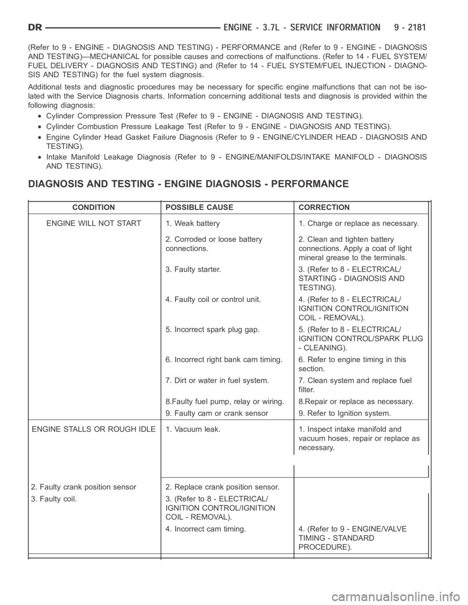
DIAGNOSIS AND TESTING - ENGINE DIAGNOSIS - PERFORMANCE
CONDITION POSSIBLE CAUSE CORRECTION
ENGINE WILL NOT START 1. Weak battery 1. Charge or replace as necessary.
2. Corroded or loose battery
connections.2. Clean and tighten battery
connections. Apply a coat of light
mineral grease to the terminals.
3. Faulty starter. 3. (Refer to 8 - ELECTRICAL/
STARTING - DIAGNOSIS AND
TESTING).
4. Faulty coil or control unit. 4. (Refer to 8 - ELECTRICAL/
IGNITION CONTROL/IGNITION
COIL - REMOVAL).
5. Incorrect spark plug gap. 5. (Refer to 8 - ELECTRICAL/
IGNITION CONTROL/SPARK PLUG
- CLEANING).
6. Incorrect right bank cam timing. 6. Refer to engine timing in this
section.
7. Dirt or water in fuel system. 7. Clean system and replace fuel
filter.
8.Faulty fuel pump, relay or wiring. 8.Repair or replace as necessary.
9. Faulty cam or crank sensor 9. Refer to Ignition system.
ENGINE STALLS OR ROUGH IDLE 1. Vacuum leak. 1. Inspect intake manifold and
vacuum hoses, repair or replace as
necessary.
2. Faulty crank position sensor 2. Replace crank position sensor.
3. Faulty coil. 3. (Refer to 8 - ELECTRICAL/
IGNITION CONTROL/IGNITION
COIL - REMOVAL).
4. Incorrect cam timing. 4. (Refer to 9 - ENGINE/VALVE
TIMING - STANDARD
PROCEDURE).
Page 1492 of 5267
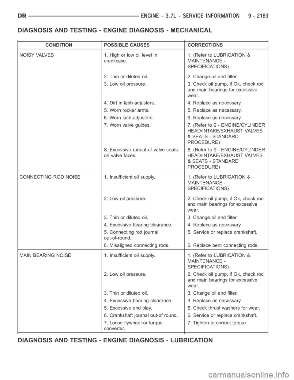
DIAGNOSIS AND TESTING - ENGINE DIAGNOSIS - MECHANICAL
CONDITION POSSIBLE CAUSES CORRECTIONS
NOISY VALVES 1. High or low oil level in
crankcase.1. (Refer to LUBRICATION &
MAINTENANCE -
SPECIFICATIONS)
2. Thin or diluted oil. 2. Change oil and filter.
3. Low oil pressure. 3. Check oil pump, if Ok, check rod
and main bearings for excessive
wear.
4. Dirt in lash adjusters. 4. Replace as necessary.
5. Worn rocker arms. 5. Replace as necessary.
6. Worn lash adjusters 6. Replace as necessary.
7. Worn valve guides. 7. (Refer to 9 - ENGINE/CYLINDER
HEAD/INTAKE/EXHAUST VALVES
& SEATS - STANDARD
PROCEDURE)
8. Excessive runout of valve seats
on valve faces.8. (Refer to 9 - ENGINE/CYLINDER
HEAD/INTAKE/EXHAUST VALVES
& SEATS - STANDARD
PROCEDURE)
CONNECTING ROD NOISE 1. Insufficient oil supply. 1. (Refer to LUBRICATION&
MAINTENANCE -
SPECIFICATIONS)
2. Low oil pressure. 2. Check oil pump, if Ok, check rod
and main bearings for excessive
wear.
3. Thin or diluted oil. 3. Change oil and filter.
4. Excessive bearing clearance. 4. Replace as necessary.
5. Connecting rod journal
out-of-round.5. Service or replace crankshaft.
6. Misaligned connecting rods. 6. Replace bent connecting rods.
MAIN BEARING NOISE 1. Insufficient oil supply. 1. (Refer to LUBRICATION &
MAINTENANCE -
SPECIFICATIONS)
2. Low oil pressure. 2. Check oil pump, if Ok, check rod
and main bearings for excessive
wear.
3. Thin or diluted oil. 3. Change oil and filter.
4. Excessive bearing clearance. 4. Replace as necessary.
5. Excessive end play. 5. Check thrust washers for wear.
6. Crankshaft journal out-of round. 6. Service or replace crankshaft.
7. Loose flywheel or torque
converter.7. Tighten to correct torque
DIAGNOSIS AND TESTING - ENGINE DIAGNOSIS - LUBRICATION
Page 1538 of 5267
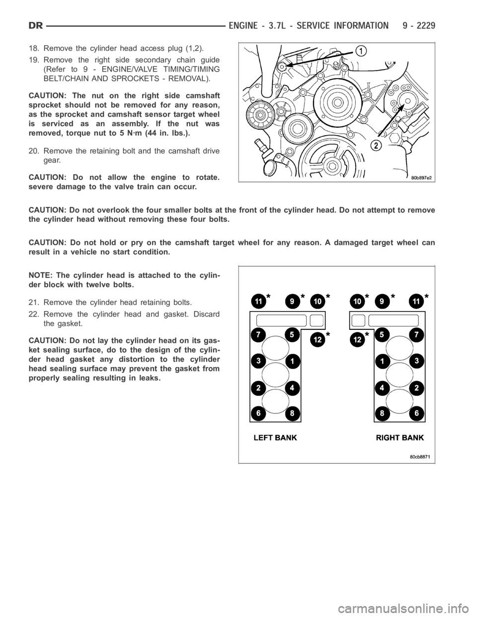
18. Remove the cylinder head access plug (1,2).
19. Remove the right side secondary chain guide
(Refer to 9 - ENGINE/VALVE TIMING/TIMING
BELT/CHAIN AND SPROCKETS - REMOVAL).
CAUTION: The nut on the right side camshaft
sprocket should not be removed for any reason,
as the sprocket and camshaft sensor target wheel
is serviced as an assembly. If the nut was
removed, torque nut to 5 Nꞏm (44 in. lbs.).
20. Remove the retaining bolt and the camshaft drive
gear.
CAUTION: Do not allow the engine to rotate.
severe damage to the valve train can occur.
CAUTION: Do not overlook the four smaller bolts at the front of the cylinderhead.Donotattempttoremove
the cylinder head without removing these four bolts.
CAUTION: Do not hold or pry on the camshaft target wheel for any reason. A damaged target wheel can
result in a vehicle no start condition.
NOTE: The cylinder head is attached to the cylin-
der block with twelve bolts.
21. Remove the cylinder head retaining bolts.
22. Remove the cylinder head and gasket. Discard
the gasket.
CAUTION: Do not lay the cylinder head on its gas-
ket sealing surface, do to the design of the cylin-
der head gasket any distortion to the cylinder
head sealing surface may prevent the gasket from
properly sealing resulting in leaks.
Page 1541 of 5267
CAUTION: The nut on the right side camshaft sprocket should not be removed for any reason, as the
sprocket and camshaft sensor target wheel is serviced as an assembly. If the nut was removed, torque nut
to 5 NM ( 60 in. lbs.).
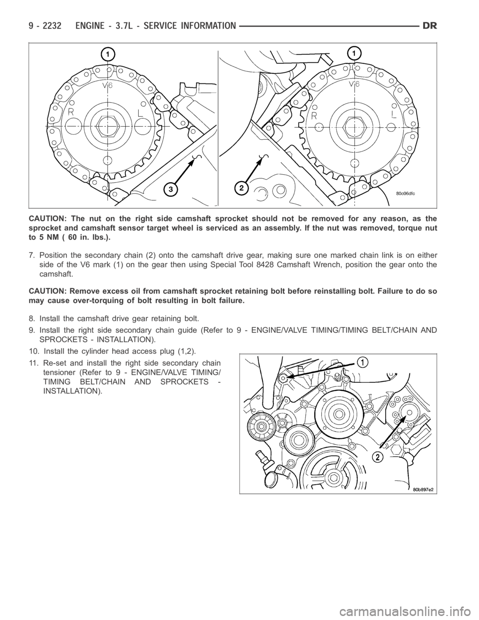
7. Position the secondary chain (2) onto the camshaft drive gear, making sure one marked chain link is on either
side of the V6 mark (1) on the gear then using Special Tool 8428 Camshaft Wrench, position the gear onto the
camshaft.
CAUTION: Remove excess oil from camshaft sprocket retaining bolt before reinstalling bolt. Failure to do so
may cause over-torquing of bolt resulting in bolt failure.
8. Install the camshaft drive gear retaining bolt.
9. Install the right side secondary chain guide (Refer to 9 - ENGINE/VALVE TIMING/TIMING BELT/CHAIN AND
SPROCKETS - INSTALLATION).
10. Install the cylinder head access plug (1,2).
11. Re-set and install the right side secondary chain
tensioner (Refer to 9 - ENGINE/VALVE TIMING/
TIMING BELT/CHAIN AND SPROCKETS -
INSTALLATION).
Page 1557 of 5267
INSPECTION
NOTE: Thoroughly inspect the connecting rod bearing bores and main bearing bores for scoring, blueing or
severe scratches. Further disassembly may be required.
If connecting rod bearing bores show damage, the cylinder heads must be removed to service the piston and rod
assemblies. If the bedplate or the cylinder block main bearing bores show damage the engine must be replaced.
1. If required, remove the main bearing halves from the cylinder block and bedplate.
2. Thoroughly clean the bedplate to cylinder block sealing surfaces and main bearing bores. Remove all oil and
sealant residue.
3. Inspect the bedplate main bearing bores for cracks, scoring or severe blueing. If either condition exists the
engine must be replaced.
4. Inspect the crankshaft thrust washers for scoring, scratches, wear or blueing. If either condition exist replace the
thrust washers.
5. Inspect the oil pan gasket/windage tray for splits, tears or cracks in the gasket sealing surfaces. Replace gasket
as necessary.
INSTALLATION
CAUTION: Main bearings are select fit. Refer to
Crankshaft Main Bearings in this section for
proper bearing selections.
CAUTION: When installing crankshaft, use care
not to damage bearing surfaces on the crankshaft.
NOTE: Apply sealant to the tone wheel retaining
screws prior to installation.
1. Lubricate upper main bearing halves with clean
engine oil.
2. Install the crankshaft tone wheel. Torque the
mountingscrewsto15Nꞏm(11ft.lbs.).
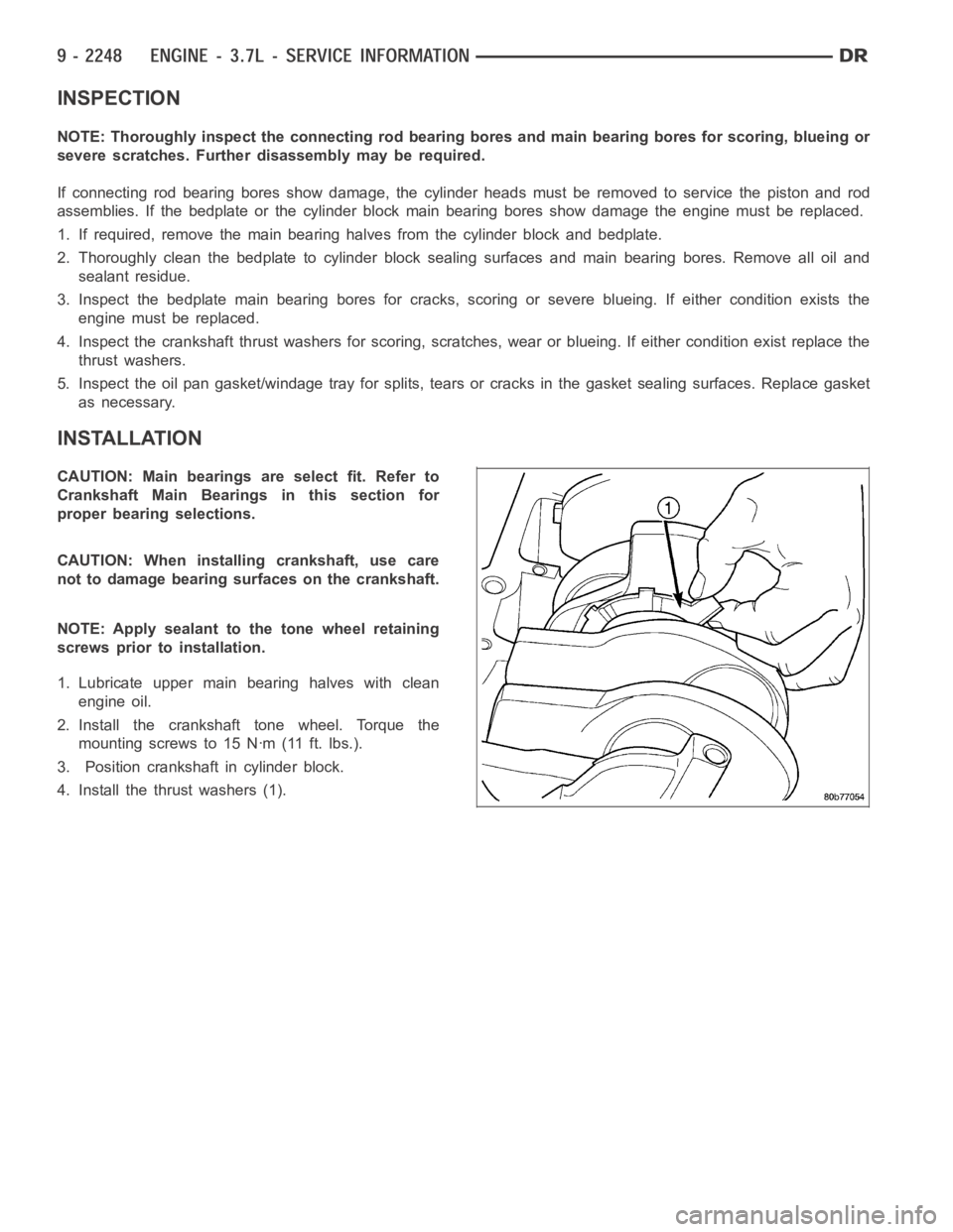
3. Position crankshaft in cylinder block.
4. Install the thrust washers (1).