Page 837 of 5267

4.ECM
Reconnect the ECM harness connectors.
Reconnect the APPS harness connector.
While monitoring with the scan tool, disconnect the sensor connector.
Did a APPS No. 1 and APPS No. 2 voltage too low DTC set?
Ye s>>
Go To 5
No>>
Replace and program the ECM in accordance with the Service Information.
Perform POWERTRAIN VERIFICATION TEST VER - 1 (DIESEL). (Refer to 8 - ELECTRICAL/ELEC-
TRONIC CONTROL MODULES/ENGINE CONTROL MODULE - DIAGNOSIS AND TESTING)
5.APPS
Reconnect the APPS harness connector.
Monitor the APPS No. 1 and APPS No. 2 voltage with the scan tool while depressing the throttle pedal.
Is the voltage transition shown on the scan tool smooth while depressing thethrottleandisthevolt-
age from APPS 1 twice as much as from APPS2
Ye s>>
Refer to the INTERMITTENT CONDITION Symptom (Diagnostic Procedure). (Refer to 9 - ENGINE -
DIAGNOSIS AND TESTING)
No>>
Replace the APPS.
Perform POWERTRAIN VERIFICATION TEST VER - 1 (DIESEL). (Refer to 8 - ELECTRICAL/ELEC-
TRONIC CONTROL MODULES/ENGINE CONTROL MODULE - DIAGNOSIS AND TESTING)
Page 845 of 5267

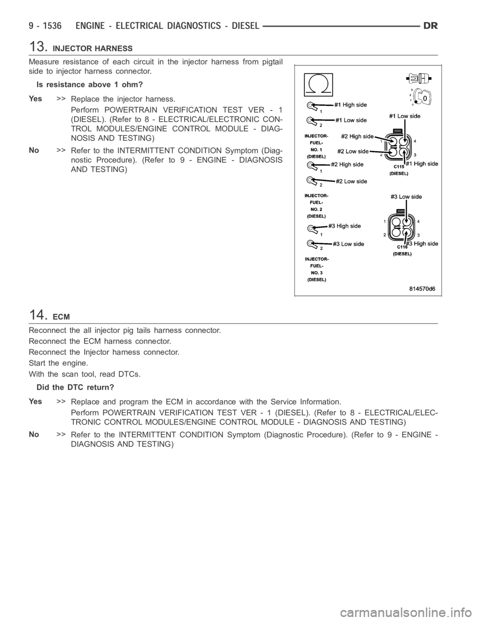
13.INJECTOR HARNESS
Measure resistance of each circuit in the injector harness from pigtail
side to injector harness connector.
Is resistance above 1 ohm?
Ye s>>
Replace the injector harness.
Perform POWERTRAIN VERIFICATION TEST VER - 1
(DIESEL). (Refer to 8 - ELECTRICAL/ELECTRONIC CON-
TROL MODULES/ENGINE CONTROL MODULE - DIAG-
NOSIS AND TESTING)
No>>
Refer to the INTERMITTENT CONDITION Symptom (Diag-
nostic Procedure). (Refer to 9 - ENGINE - DIAGNOSIS
AND TESTING)
14.ECM
Reconnect the all injector pig tails harness connector.
Reconnect the ECM harness connector.
Reconnect the Injector harness connector.
Start the engine.
With the scan tool, read DTCs.
Did the DTC return?
Ye s>>
Replace and program the ECM in accordance with the Service Information.
Perform POWERTRAIN VERIFICATION TEST VER - 1 (DIESEL). (Refer to 8 - ELECTRICAL/ELEC-
TRONIC CONTROL MODULES/ENGINE CONTROL MODULE - DIAGNOSIS AND TESTING)
No>>
Refer to the INTERMITTENT CONDITION Symptom (Diagnostic Procedure). (Refer to 9 - ENGINE -
DIAGNOSIS AND TESTING)
Page 852 of 5267
13.INJECTOR HARNESS
Measure resistance of each circuit in the injector harness from pigtail
side to injector harness connector.
Is resistance above 1 ohm?
Ye s>>
Replace the injector harness.
Perform POWERTRAIN VERIFICATION TEST VER - 1
(DIESEL). (Refer to 8 - ELECTRICAL/ELECTRONIC CON-
TROL MODULES/ENGINE CONTROL MODULE - DIAG-
NOSIS AND TESTING)
No>>
Refer to the INTERMITTENT CONDITION Symptom (Diag-
nostic Procedure). (Refer to 9 - ENGINE - DIAGNOSIS
AND TESTING)
14.ECM
Reconnect all the injector pig tail harness connectors to the Injectors.
Reconnect the ECM harness connector.
Reconnect the Injector harness connector.
Start the engine.
With the scan tool, read DTCs.
Did the DTC return?
Ye s>>
Replace and program the ECM in accordance with the Service Information.
Perform POWERTRAIN VERIFICATION TEST VER - 1 (DIESEL). (Refer to 8 - ELECTRICAL/ELEC-
TRONIC CONTROL MODULES/ENGINE CONTROL MODULE - DIAGNOSIS AND TESTING)
No>>
Te s t C o m p l e t e .
Page 857 of 5267

When Monitored:
Ignition on.
Set Condition:
Low voltage detected at the WIF signal circuit at the ECM.
Possible Causes
OTHER DTC’S PRESENT
WATER IN FUEL
ECM
INTERMITTENT CONDITION
Always perform the Pre-Diagnostic Troubleshooting procedure before proceeding. (Refer to 9 - ENGINE -
DIAGNOSIS AND TESTING)
Diagnostic Test
1.OTHER DTC’S PRESENT
With the scan tool, read DTCs.
Do you have any additional water in fuel DTC’s?
Ye s>>
Repair other Water in fuel sensor DTC’s first.
Perform POWERTRAIN VERIFICATION TEST VER - 1 (DIESEL). (Refer to 8 - ELECTRICAL/ELEC-
TRONIC CONTROL MODULES/ENGINE CONTROL MODULE - DIAGNOSIS AND TESTING)
No>>
Go To 2
2.WAT E R I N F U E L
Using the service publications as a guide, drain the water in fuel separator.
Did the DTC become inactive after draining the water in fuel separator?
Ye s>>
Clear DTC, repair complete.
Perform POWERTRAIN VERIFICATION TEST VER - 1 (DIESEL). (Refer to 8 - ELECTRICAL/ELEC-
TRONIC CONTROL MODULES/ENGINE CONTROL MODULE - DIAGNOSIS AND TESTING)
No>>
Go To 3
3.ECM
Disconnect the WIF sensor harness connector.
NOTE: Check connectors - Clean/repair as necessary.
Using the scan tool, monitor for DTC’s while connecting a jumper wire
between the (G123) signal circuit of the water in fuel sensor and battery
voltage.
Did the water in fuel light go out?
Ye s>>
Refer to the INTERMITTENT CONDITION Symptom (Diag-
nostic Procedure). (Refer to 9 - ENGINE - DIAGNOSIS
AND TESTING)
No>>
Replace and program the ECM in accordance with the Ser-
vice Information.
Perform POWERTRAIN VERIFICATION TEST VER - 1
(DIESEL). (Refer to 8 - ELECTRICAL/ELECTRONIC CON-
TROL MODULES/ENGINE CONTROL MODULE - DIAG-
NOSIS AND TESTING)
Page 860 of 5267

4.HIGH RESISTANCE IN THE GROUND CIRCUIT
Measure the voltage between the generator case and the B- post of the battery.
Is the voltage above .1 volts?
Ye s>>
Repair the high resistance in the ground circuit.
Perform POWERTRAIN VERIFICATION TEST VER - 1 (DIESEL). (Refer to 8 - ELECTRICAL/ELEC-
TRONIC CONTROL MODULES/ENGINE CONTROL MODULE - DIAGNOSIS AND TESTING)
No>>
Go To 5
5.GENERATOR
Disconnect the Generator field harness connector.
NOTE: Check connectors - Clean/repair as necessary.
Measure the resistance between the generator field terminals.
Is the resistance between .5 and 15 Ohms?
Ye s>>
Go To 6
No>>
Replace the generator.
Perform POWERTRAIN VERIFICATION TEST VER - 1
(DIESEL). (Refer to 8 - ELECTRICAL/ELECTRONIC CON-
TROL MODULES/ENGINE CONTROL MODULE - DIAG-
NOSIS AND TESTING)
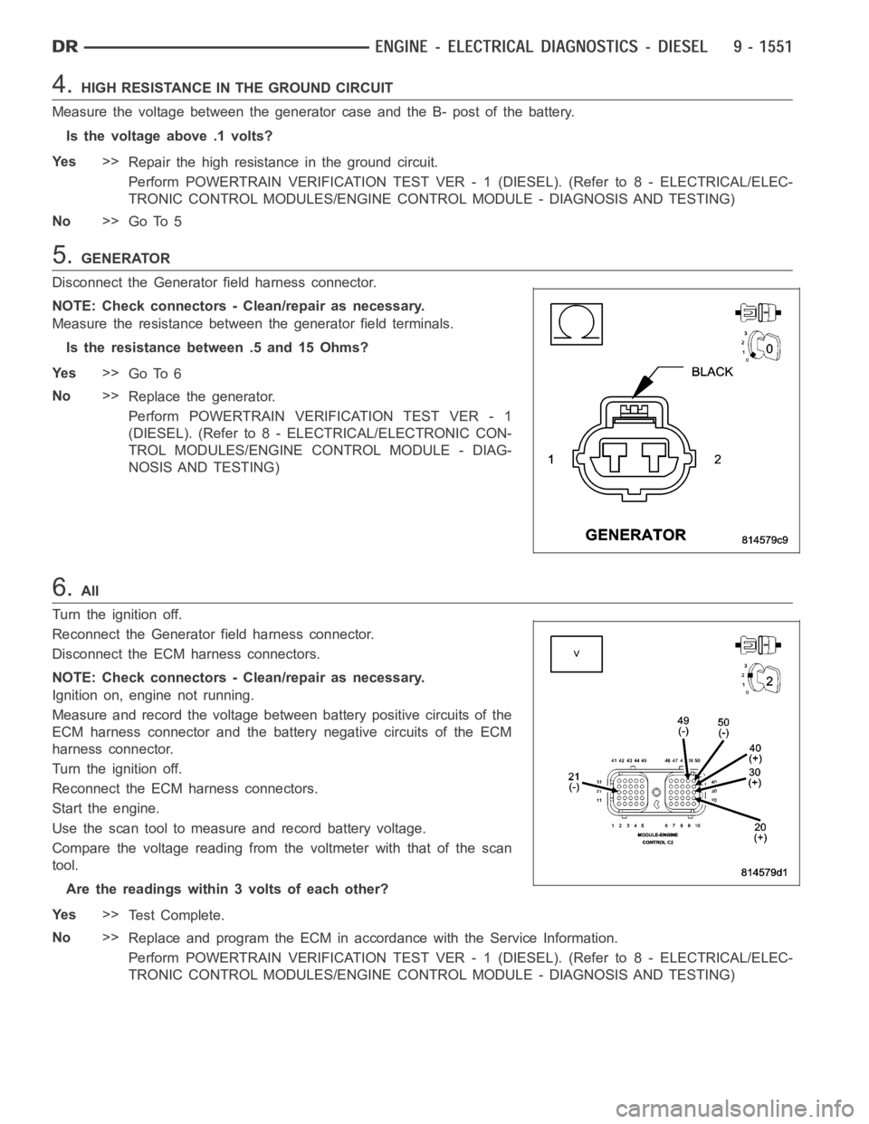
6.All
Turn the ignition off.
Reconnect the Generator field harness connector.
Disconnect the ECM harness connectors.
NOTE: Check connectors - Clean/repair as necessary.
Ignition on, engine not running.
Measure and record the voltage between battery positive circuits of the
ECM harness connector and the battery negative circuits of the ECM
harness connector.
Turn the ignition off.
Reconnect the ECM harness connectors.
Start the engine.
Use the scan tool to measure and record battery voltage.
Compare the voltage reading from the voltmeter with that of the scan
tool.
Are the readings within 3 volts of each other?
Ye s>>
Te s t C o m p l e t e .
No>>
Replace and program the ECM in accordance with the Service Information.
Perform POWERTRAIN VERIFICATION TEST VER - 1 (DIESEL). (Refer to 8 - ELECTRICAL/ELEC-
TRONIC CONTROL MODULES/ENGINE CONTROL MODULE - DIAGNOSIS AND TESTING)
Page 904 of 5267

U1403-IMPLAUSIBLE FUEL LEVEL SIGNAL RECEIVED
For a complete wiring diagramRefer to Section 8W.
When Monitored:
Ignition on.
Set Condition:
The fuel volume message the ECM is receiving is implausible. The circuit iscontinuously monitored. One Trip
fault.
Possible Causes
CAN B OPEN OR SHORTED
CLUSTER MODULE
TOTALLY INTEGRATED POWER MODULE (TIPM)
ECM
Always perform the Pre-Diagnostic Troubleshooting procedure before proceeding. (Refer to 9 - ENGINE -
DIAGNOSIS AND TESTING).
Theory of Operation
The Totally Integrated Power Module isn’t receiving a fuel volume signal over CAN B from the Cluster Module. The
TIPM has to send the PCM a fuel volume signal over CAN C. The signal the TIPM sendsoverCANCisimplau-
sible.
Diagnostic Test
1.ACTIVE DTC
Ignition on, engine not running.
With a scan tool read DTCs.
Is the DTC active at this time?
Ye s>>
Go To 2
No>>
Refer to the INTERMITTENT CONDITION Diagnostic Procedure.
Perform the POWERTRAIN VERIFICATION TEST. (Refer to 9 - ENGINE - STANDARD PROCEDURE)
2.CAN B BUS HARDWARE DTCS ALSO ACTIVE
With a scan tool check for DTCs in the FCM (TIPM).
Are any CAN B Hardware related DTCs active at this time?
Ye s>>
(Refer to 8 - ELECTRICAL/ELECTRONIC CONTROL MODULES - DIAGNOSIS AND TESTING) for the
appropriate diagnostic procedures.
Perform BODY VERIFICATION TEST – VER 1.
No>>
Replace and program the Powertrain Control Module per Service Information.
Perform the POWERTRAIN VERIFICATION TEST. (Refer to 9 - ENGINE - STANDARD PROCEDURE)
Page 906 of 5267
4.ACTIVE DTCS IN THE FCM
With the scan tool, select ECU View and select FCM (TIPM).
With the scan tool, read active DTCs.
Is the U0001-NO COMMUNICATION ON THE CAN C BUS CIRCUIT ACTIVE in the FCM at this time?
Ye s>>
Replace the ABS Module per Service Information.
Perform the POWERTRAIN VERIFICATION TEST. (Refer to 9 - ENGINE - STANDARD PROCEDURE)
No>>
Replace and program the Powertrain Control Module per Service Information.
Perform the POWERTRAIN VERIFICATION TEST. (Refer to 9 - ENGINE - STANDARD PROCEDURE)
Page 909 of 5267

U1421-IMPLAUSIBLE IGNITION KEY OFF TIME RECEIVED
For a complete wiring diagramRefer to Section 8W.
When Monitored:
Ignition on.
Set Condition:
The fuel volume message the ECM is receiving is implausible. The circuit iscontinuously monitored. One Trip
fault.
Possible Causes
CAN B OPEN OR SHORTED
CLUSTER MODULE
FCM (TOTALLY INTEGRATED POWER MODULE)
ECM
Always perform the Pre-Diagnostic Troubleshooting procedure before proceeding. (Refer to 9 - ENGINE -
DIAGNOSIS AND TESTING).
Theory of Operation
The Totally Integrated Power Module (TIPM) isn’t receiving a fuel volume signal over CAN B from the Cluster Mod-
ule. The TIPM has to send the PCM a fuel volume signal over CAN C. The signal the TIPM sends over CAN C is
implausible.
Diagnostic Test
1.ACTIVE DTC
Ignition on, engine not running.
With a scan tool read DTCs.
Is the DTC active at this time?
Ye s>>
Go To 2
No>>
Refer to the INTERMITTENT CONDITION Diagnostic Procedure.
Perform the POWERTRAIN VERIFICATION TEST. (Refer to 9 - ENGINE - STANDARD PROCEDURE)
2.CAN B BUS HARDWARE DTCS ALSO ACTIVE
With a scan tool check for DTCs in the TIPM.
Are any CAN B Hardware related DTCs active at this time?
Ye s>>
(Refer to 8 - ELECTRICAL/ELECTRONIC CONTROL MODULES - DIAGNOSIS AND TESTING) for the
appropriate diagnostic procedures.
Perform BODY VERIFICATION TEST – VER 1.
No>>
Replace and program the Powertrain Control Module per Service Information.
Perform the POWERTRAIN VERIFICATION TEST. (Refer to 9 - ENGINE - STANDARD PROCEDURE)