Page 988 of 5267

2.THERMOSTAT OPERATION
NOTE: This test works best if performed on a cold engine (cold soak)
Ignition on, engine not running.
With a scan tool, read the Eng Coolant Tmp Deg value. If the engine was allowed to sit overnight (cold soak), the
temperature value should be a sensible value that is somewhere close to theambient temperature.
NOTE: If engine coolant temperature is above 82°C (180°F), allow the engine to cool until 65°C (150°F) is
reached.
Start the Engine.
During engine warm-up monitor the Eng Coolant Tmp Deg value. The temp deg value change should be a smooth
transition from start up to normal operating temp 82°C (180°F). Also monitor the actual coolant temperature with a
thermometer.
NOTE: As the engine warms up to operating temperature, the actual coolant temperature (thermometer read-
ing) and the scan tool Eng Coolant Tmp Deg values should stay relatively close to each other.
Using the appropriate service information, determine the proper openingtemperature of the thermostat.
Did the thermostat open at the proper temperature?
Ye s>>
Go To 3
No>>
Replace the thermostat.
Perform the POWERTRAIN VERIFICATION TEST. (Refer to 9 - ENGINE - STANDARD PROCEDURE)
3.ECT SENSOR OPERATION
Ignition on, engine not running.
With a scan tool, read the Eng Coolant Tmp Deg value. If the engine was allowed to sit overnight (cold soak), the
temperature value should be a sensible value that is somewhere close to theambient temperature.
NOTE: If engine coolant temperature is above 82°C (180°F), allow the engine to cool until 65°C (150°F) is
reached.
Start the Engine.
During engine warm-up monitor the Eng Coolant Tmp Deg value. The temp deg value change should be a smooth
transition from start up to normal operating temp 82°C (180°F). Also monitor the actual coolant temperature with a
thermometer.
NOTE: As the engine warms up to operating temperature, the actual coolant temperature (thermometer read-
ing) and the scan tools Eng Coolant Tmp Deg value should stay relatively close to each other.
Is the thermometer reading relatively close to the scan tool ECT reading?
Ye s>>
Te s t C o m p l e t e .
No>>
Replace the Engine Coolant Temperature Sensor.
Perform the POWERTRAIN VERIFICATION TEST. (Refer to 9 - ENGINE - STANDARD PROCEDURE)
Page 991 of 5267

3.(K41) O2 SENSOR 1/1 SIGNAL CIRCUIT SHORTED TO GROUND
Turn the ignition off.
Disconnect the C1 PCM harness connector.
Measure the resistance between ground and the (K41) O2 Sensor 1/1
Signal circuit at the 1/1 O2 Sensor harness connector.
Istheresistancebelow100ohms?
Ye s>>
Repair the short to ground in the (K41) O2 Sensor 1/1Sig-
nal circuit.
Perform the POWERTRAIN VERIFICATION TEST. (Refer to
9 - ENGINE - STANDARD PROCEDURE)
No>>
Go To 4
4.(K41) O2 SENSOR 1/1 SIGNAL CIRCUIT SHORTED TO (K900) SENSOR GROUND CIRCUIT
Measure the resistance between the (K41) O2 Sensor 1/1 Signal circuit
and the (K900) Sensor ground circuit at the 1/1 O2 Sensor harness
connector.
Istheresistancebelow100ohms?
Ye s>>
Repair the short between the (K900) Sensor ground circuit
and the (K41) O2 Sensor 1/1 Signal circuit.
Perform the POWERTRAIN VERIFICATION TEST. (Refer to
9 - ENGINE - STANDARD PROCEDURE)
No>>
Go To 5
5.PCM
NOTE: Before continuing, check the PCM harness connector terminals for corrosion, damage, or terminal
push out. Repair as necessary.
Using the schematics as a guide, inspect the wire harness and connectors. Pay particular attention to all Power and
Ground circuits.
Were there any problems found?
Ye s>>
Repair as necessary.
Perform the POWERTRAIN VERIFICATION TEST. (Refer to 9 - ENGINE - STANDARD PROCEDURE)
No>>
Replace and program the Powertrain Control Module per Service Information.
Perform the POWERTRAIN VERIFICATION TEST. (Refer to 9 - ENGINE - STANDARD PROCEDURE)
Page 996 of 5267

7.(K99) O2 SENSOR 1/1 HEATER CONTROL CIRCUIT OPEN
Turn the ignition off.
Disconnect the C3 PCM harness connector.
Measure the resistance of the (K99) O2 Sensor 1/1 Heater Control cir-
cuit from the O2 Sensor harness connector to the PCM harness con-
nector.
Is the resistance below 5.0 ohms?
Ye s>>
Go To 8
No>>
Repair the open in the (K99) O2 Sensor 1/1 Heater Control
Circuit (PWM) circuit.
Perform the POWERTRAIN VERIFICATION TEST. (Refer to
9 - ENGINE - STANDARD PROCEDURE)
8.PCM
NOTE: Before continuing, check the PCM harness connector terminals for corrosion, damage, or terminal
push out. Repair as necessary.
Using the schematics as a guide, inspect the wire harness and connectors. Pay particular attention to all Power and
Ground circuits.
Were there any problems found?
Ye s>>
Repair as necessary.
Perform the POWERTRAIN VERIFICATION TEST. (Refer to 9 - ENGINE - STANDARD PROCEDURE)
No>>
Replace and program the Powertrain Control Module per Service Information.
Perform the POWERTRAIN VERIFICATION TEST. (Refer to 9 - ENGINE - STANDARD PROCEDURE)
Page 1002 of 5267

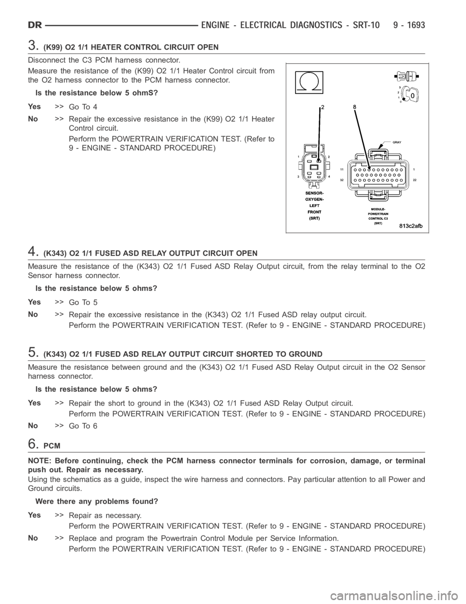
3.(K99) O2 1/1 HEATER CONTROL CIRCUIT OPEN
Disconnect the C3 PCM harness connector.
Measure the resistance of the (K99) O2 1/1 Heater Control circuit from
the O2 harness connector to the PCM harness connector.
Is the resistance below 5 ohmS?
Ye s>>
Go To 4
No>>
Repair the excessive resistance in the (K99) O2 1/1 Heater
Control circuit.
Perform the POWERTRAIN VERIFICATION TEST. (Refer to
9 - ENGINE - STANDARD PROCEDURE)
4.(K343) O2 1/1 FUSED ASD RELAY OUTPUT CIRCUIT OPEN
Measure the resistance of the (K343) O2 1/1 Fused ASD Relay Output circuit,from the relay terminal to the O2
Sensor harness connector.
Is the resistance below 5 ohms?
Ye s>>
Go To 5
No>>
Repair the excessive resistance in the (K343) O2 1/1 Fused ASD relay outputcircuit.
Perform the POWERTRAIN VERIFICATION TEST. (Refer to 9 - ENGINE - STANDARD PROCEDURE)
5.(K343) O2 1/1 FUSED ASD RELAY OUTPUT CIRCUIT SHORTED TO GROUND
Measure the resistance between ground and the (K343) O2 1/1 Fused ASD RelayOutput circuit in the O2 Sensor
harness connector.
Is the resistance below 5 ohms?
Ye s>>
Repair the short to ground in the (K343) O2 1/1 Fused ASD Relay Output circuit.
Perform the POWERTRAIN VERIFICATION TEST. (Refer to 9 - ENGINE - STANDARD PROCEDURE)
No>>
Go To 6
6.PCM
NOTE: Before continuing, check the PCM harness connector terminals for corrosion, damage, or terminal
push out. Repair as necessary.
Using the schematics as a guide, inspect the wire harness and connectors. Pay particular attention to all Power and
Ground circuits.
Were there any problems found?
Ye s>>
Repair as necessary.
Perform the POWERTRAIN VERIFICATION TEST. (Refer to 9 - ENGINE - STANDARD PROCEDURE)
No>>
Replace and program the Powertrain Control Module per Service Information.
Perform the POWERTRAIN VERIFICATION TEST. (Refer to 9 - ENGINE - STANDARD PROCEDURE)
Page 1005 of 5267

4.(K127) O2 HEATER RELAY CONTROL CIRCUIT OPEN
Turn the ignition off.
Disconnect the PCM harness connectors.
Measure the resistance of the (K127) O2 Heater Relay Control circuit from the PDC (Heater Relay) connector to the
PCM harness connector.
Is the resistance below 5.0 ohms?
Ye s>>
Go To 5
No>>
Repair the open in the (K127) O2 Heater Relay Control circuit.
Perform POWERTRAIN VERIFICATION TEST. (Refer to 9 - ENGINE - STANDARD PROCEDURE)
5.(K127) O2 HEATER RELAY CONTROL CIRCUIT SHORTED TO GROUND
Measure the resistance between ground and the (K127) O2 Heater Relay Control circuit at the PDC connector.
Istheresistancebelow100ohms?
Ye s>>
Repair the short to ground in the (K127) O2 Sensor Heater Relay Control circuit.
Perform POWERTRAIN VERIFICATION TEST. (Refer to 9 - ENGINE - STANDARD PROCEDURE)
No>>
Go To 6
6.O2 HEATER ELEMENT
NOTE: Allow the O2 Sensor to cool to room temperature.
Disconnect the O2 Sensor harness connector.
Measure the resistance across the O2 Sensor Heater element component side.
NOTE: The resistance value will increase with warmer temperatures.
Is the resistance between 4.0 and 5.0 ohms at 70° F (21.1°C)?
Ye s>>
Go To 7
No>>
Replace the O2 Sensor.
Perform POWERTRAIN VERIFICATION TEST. (Refer to 9 - ENGINE - STANDARD PROCEDURE)
7.PCM
NOTE: Before continuing, check the PCM harness connector terminals for corrosion, damage, or terminal
push out. Repair as necessary.
Using the schematics as a guide, inspect the wire harness and connectors. Pay particular attention to all Power and
Ground circuits.
If there are not possible causes remaining, view repair.
Repair
Replace and program the Powertrain Control Module per Service Information.
Perform POWERTRAIN VERIFICATION TEST. (Refer to 9 - ENGINE - STANDARD PROCEDURE)
Page 1009 of 5267
6.PCM
NOTE: Before continuing, check the PCM harness connector terminals for corrosion, damage, or terminal
push out. Repair as necessary.
Using the schematics as a guide, inspect the wire harness and connectors. Pay particular attention to all Power and
Ground circuits.
Were there any problems found?
Ye s>>
Repair as necessary.
Perform the POWERTRAIN VERIFICATION TEST. (Refer to 9 - ENGINE - STANDARD PROCEDURE)
No>>
Replace and program the Powertrain Control Module per Service Information.
Perform the POWERTRAIN VERIFICATION TEST. (Refer to 9 - ENGINE - STANDARD PROCEDURE)
Page 1014 of 5267

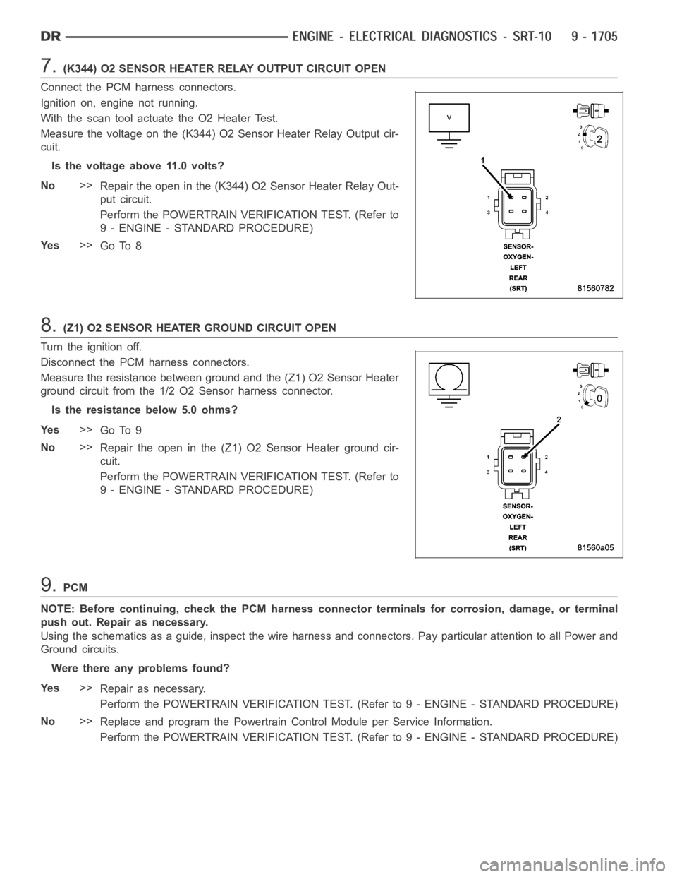
7.(K344) O2 SENSOR HEATER RELAY OUTPUT CIRCUIT OPEN
Connect the PCM harness connectors.
Ignition on, engine not running.
With the scan tool actuate the O2 Heater Test.
Measure the voltage on the (K344) O2 Sensor Heater Relay Output cir-
cuit.
Is the voltage above 11.0 volts?
No>>
Repair the open in the (K344) O2 Sensor Heater Relay Out-
put circuit.
Perform the POWERTRAIN VERIFICATION TEST. (Refer to
9 - ENGINE - STANDARD PROCEDURE)
Ye s>>
Go To 8
8.(Z1) O2 SENSOR HEATER GROUND CIRCUIT OPEN
Turn the ignition off.
Disconnect the PCM harness connectors.
Measure the resistance between ground and the (Z1) O2 Sensor Heater
ground circuit from the 1/2 O2 Sensor harness connector.
Is the resistance below 5.0 ohms?
Ye s>>
Go To 9
No>>
Repair the open in the (Z1) O2 Sensor Heater ground cir-
cuit.
Perform the POWERTRAIN VERIFICATION TEST. (Refer to
9 - ENGINE - STANDARD PROCEDURE)
9.PCM
NOTE: Before continuing, check the PCM harness connector terminals for corrosion, damage, or terminal
push out. Repair as necessary.
Using the schematics as a guide, inspect the wire harness and connectors. Pay particular attention to all Power and
Ground circuits.
Were there any problems found?
Ye s>>
Repair as necessary.
Perform the POWERTRAIN VERIFICATION TEST. (Refer to 9 - ENGINE - STANDARD PROCEDURE)
No>>
Replace and program the Powertrain Control Module per Service Information.
Perform the POWERTRAIN VERIFICATION TEST. (Refer to 9 - ENGINE - STANDARD PROCEDURE)
Page 1021 of 5267
6.(Z1) HEATER GROUND CIRCUIT OPEN
Using a 12-volt test light connected to 12-volts, probe the (Z1) O2
Heater Ground circuit at the O2 Sensor harness connector.
Does the test light illuminate brightly?
Ye s>>
Go To 7
No>>
Repair the open in the (Z1) O2 Sensor Heater ground cir-
cuit.
Perform the POWERTRAIN VERIFICATION TEST. (Refer to
9 - ENGINE - STANDARD PROCEDURE)
7.PCM
NOTE: Before continuing, check the PCM harness connector terminals for corrosion, damage, or terminal
push out. Repair as necessary.
Using the schematics as a guide, inspect the wire harness and connectors. Pay particular attention to all Power and
Ground circuits.
Were there any problems found?
Ye s>>
Repair as necessary.
Perform the POWERTRAIN VERIFICATION TEST. (Refer to 9 - ENGINE - STANDARD PROCEDURE)
No>>
Replace and program the Powertrain Control Module per Service Information.
Perform the POWERTRAIN VERIFICATION TEST. (Refer to 9 - ENGINE - STANDARD PROCEDURE)