Page 761 of 5267
When Monitored:
When the ignition is on.
Set Condition:
When the signal from the A/C Clutch output does not match the signal from theA/C Clutch feedback.
Possible Causes
WIRING HARNESS OR CONNECTIONS
A/C CLUTCH CIRCUIT SHORTED TO EXTERNAL VOLTAGE
TIPM
ECM
Always perform the Pre-Diagnostic Troubleshooting procedure before proceeding. (Refer to 9 - ENGINE -
DIAGNOSIS AND TESTING)
Diagnostic Test
1.A/C CLUTCH CIRCUIT SHORTED TO EXTERNAL VOLTAGE
Ignition off.
Disconnect the ECM and TIPM connectors.
NOTE: Check connectors - Clean/repair as necessary.
Ignition on, engine not running.
Using a Voltmeter, measure the voltage of the A/C Clutch Control Circuit between the TIPM connector and battery
negative..
Is the voltage less than 1 volt?
Ye s>>
Go To 2
Ye s>>
Repair or Replace the wiring harness.
Perform POWERTRAIN VERIFICATION TEST VER - 1 (DIESEL). (Refer to 8 - ELECTRICAL/ELEC-
TRONIC CONTROL MODULES/ENGINE CONTROL MODULE - DIAGNOSIS AND TESTING)
2.ECM
Ignition off.
Connect the ECM and TIPM connectors.
Ignition on, engine not running.
Using a back probing tool 6801, back probe the A/C clutch control circuit inthe TIPM connector.
Using a 12 volt test light connected to battery positive, check the transmission control circuit at the TIPM connector
while actuating the A/C clutch circuit with the Electronic Service Tool.
NOTE: The test light must illuminate brightly.
Compare the brightness to that of a direct connection to the battery.
Does the test light illuminate brightly?
Ye s>>
Go To 3
No>>
Replace the ECM.
Perform POWERTRAIN VERIFICATION TEST VER - 1 (DIESEL). (Refer to 8 - ELECTRICAL/ELEC-
TRONIC CONTROL MODULES/ENGINE CONTROL MODULE - DIAGNOSIS AND TESTING)
Page 762 of 5267
3.TIPM
Using a back probing tool 6801, back probe the A/C clutch power circuit in the TIPM connector.
Using a 12 volt test light connected to battery positive, check the transmission power circuit at the TIPM connector
while actuating the A/C clutch circuit with the Electronic Service Tool.
NOTE: The test light must illuminate brightly.
Compare the brightness to that of a direct connection to the battery.
Does the test light illuminate brightly?
Ye s>>
Te s t c o m p l e t e .
Perform Intermittent Condition test. (Refer to 9 - ENGINE - DIAGNOSIS AND TESTING)
No>>
Replace the TIPM.
Perform POWERTRAIN VERIFICATION TEST VER - 1 (DIESEL). (Refer to 8 - ELECTRICAL/ELEC-
TRONIC CONTROL MODULES/ENGINE CONTROL MODULE - DIAGNOSIS AND TESTING)
Page 779 of 5267
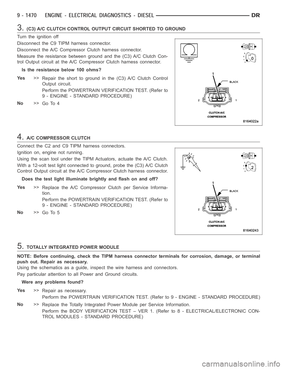
3.(C3) A/C CLUTCH CONTROL OUTPUT CIRCUIT SHORTED TO GROUND
Turn the ignition off
Disconnect the C9 TIPM harness connector.
Disconnect the A/C Compressor Clutch harness connector.
Measure the resistance between ground and the (C3) A/C Clutch Con-
trol Output circuit at the A/C Compressor Clutch harness connector.
Istheresistancebelow100ohms?
Ye s>>
Repair the short to ground in the (C3) A/C Clutch Control
Output circuit.
Perform the POWERTRAIN VERIFICATION TEST. (Refer to
9 - ENGINE - STANDARD PROCEDURE)
No>>
Go To 4
4.A/C COMPRESSOR CLUTCH
Connect the C2 and C9 TIPM harness connectors.
Ignition on, engine not running.
Using the scan tool under the TIPM Actuators, actuate the A/C Clutch.
With a 12-volt test light connected to ground, probe the (C3) A/C Clutch
Control Output circuit at the A/C Compressor Clutch harness connector.
Does the test light illuminate brightly and flash on and off?
Ye s>>
Replace the A/C Compressor Clutch per Service Informa-
tion.
Perform the POWERTRAIN VERIFICATION TEST. (Refer to
9 - ENGINE - STANDARD PROCEDURE)
No>>
Go To 5
5.TOTALLY INTEGRATED POWER MODULE
NOTE: Before continuing, check the TIPM harness connector terminals for corrosion, damage, or terminal
push out. Repair as necessary.
Using the schematics as a guide, inspect the wire harness and connectors.
Pay particular attention to all Power and Ground circuits.
Were any problems found?
Ye s>>
Repair as necessary.
Perform the POWERTRAIN VERIFICATION TEST. (Refer to 9 - ENGINE - STANDARD PROCEDURE)
No>>
Replace the Totally Integrated Power Module per Service Information.
Perform the BODY VERIFICATION TEST – VER 1. (Refer to 8 - ELECTRICAL/ELECTRONIC CON-
TROL MODULES - STANDARD PROCEDURE)
Page 782 of 5267
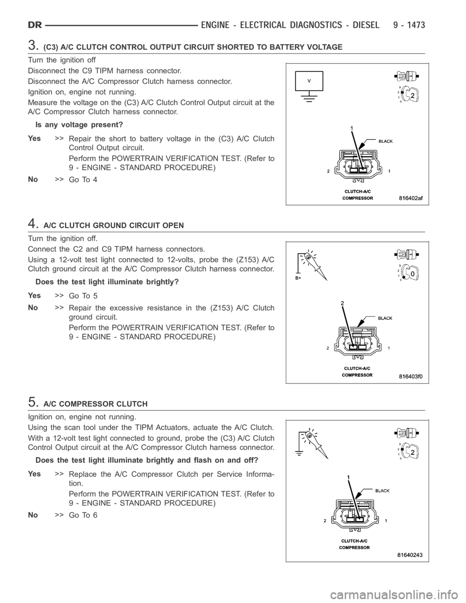
3.(C3) A/C CLUTCH CONTROL OUTPUT CIRCUIT SHORTED TO BATTERY VOLTAGE
Turn the ignition off
Disconnect the C9 TIPM harness connector.
Disconnect the A/C Compressor Clutch harness connector.
Ignition on, engine not running.
Measure the voltage on the (C3) A/C Clutch Control Output circuit at the
A/C Compressor Clutch harness connector.
Is any voltage present?
Ye s>>
Repair the short to battery voltage in the (C3) A/C Clutch
Control Output circuit.
Perform the POWERTRAIN VERIFICATION TEST. (Refer to
9 - ENGINE - STANDARD PROCEDURE)
No>>
Go To 4
4.A/C CLUTCH GROUND CIRCUIT OPEN
Turn the ignition off.
Connect the C2 and C9 TIPM harness connectors.
Using a 12-volt test light connected to 12-volts, probe the (Z153) A/C
Clutch ground circuit at the A/C Compressor Clutch harness connector.
Does the test light illuminate brightly?
Ye s>>
Go To 5
No>>
Repair the excessive resistance in the (Z153) A/C Clutch
ground circuit.
Perform the POWERTRAIN VERIFICATION TEST. (Refer to
9 - ENGINE - STANDARD PROCEDURE)
5.A/C COMPRESSOR CLUTCH
Ignition on, engine not running.
Using the scan tool under the TIPM Actuators, actuate the A/C Clutch.
With a 12-volt test light connected to ground, probe the (C3) A/C Clutch
Control Output circuit at the A/C Compressor Clutch harness connector.
Does the test light illuminate brightly and flash on and off?
Ye s>>
Replace the A/C Compressor Clutch per Service Informa-
tion.
Perform the POWERTRAIN VERIFICATION TEST. (Refer to
9 - ENGINE - STANDARD PROCEDURE)
No>>
Go To 6
Page 783 of 5267
6.TOTALLY INTEGRATED POWER MODULE
NOTE: Before continuing, check the TIPM harness connector terminals for corrosion, damage, or terminal
push out. Repair as necessary.
Using the schematics as a guide, inspect the wire harness and connectors.
Pay particular attention to all Power and Ground circuits.
Were any problems found?
Ye s>>
Repair as necessary.
Perform the POWERTRAIN VERIFICATION TEST. (Refer to 9 - ENGINE - STANDARD PROCEDURE)
No>>
Replace the Totally Integrated Power Module per Service Information.
Perform the BODY VERIFICATION TEST – VER 1. (Refer to 8 - ELECTRICAL/ELECTRONIC CON-
TROL MODULES - STANDARD PROCEDURE)
Page 786 of 5267
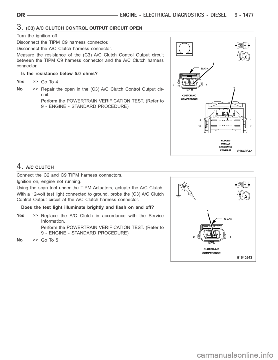
3.(C3) A/C CLUTCH CONTROL OUTPUT CIRCUIT OPEN
Turn the ignition off
Disconnect the TIPM C9 harness connector.
Disconnect the A/C Clutch harness connector.
Measure the resistance of the (C3) A/C Clutch Control Output circuit
between the TIPM C9 harness connector and the A/C Clutch harness
connector.
Is the resistance below 5.0 ohms?
Ye s>>
Go To 4
No>>
Repair the open in the (C3) A/C Clutch Control Output cir-
cuit.
Perform the POWERTRAIN VERIFICATION TEST. (Refer to
9 - ENGINE - STANDARD PROCEDURE)
4.A/C CLUTCH
Connect the C2 and C9 TIPM harness connectors.
Ignition on, engine not running.
Using the scan tool under the TIPM Actuators, actuate the A/C Clutch.
With a 12-volt test light connected to ground, probe the (C3) A/C Clutch
Control Output circuit at the A/C Clutch harness connector.
Does the test light illuminate brightly and flash on and off?
Ye s>>
Replace the A/C Clutch in accordance with the Service
Information.
Perform the POWERTRAIN VERIFICATION TEST. (Refer to
9 - ENGINE - STANDARD PROCEDURE)
No>>
Go To 5
Page 787 of 5267
5.TOTALLY INTEGRATED POWER MODULE
NOTE: Before continuing, check the TIPM harness connector terminals for corrosion, damage, or terminal
push out. Repair as necessary.
Using the schematics as a guide, inspect the wire harness and connectors.
Pay particular attention to all Power and Ground circuits.
Were any problems found?
Ye s>>
Repair as necessary.
Perform the POWERTRAIN VERIFICATION TEST. (Refer to 9 - ENGINE - STANDARD PROCEDURE)
No>>
Replace the Totally Integrated Power Module in accordance with the Service Information.
Perform the BODY VERIFICATION TEST – VER 1. (Refer to 8 - ELECTRICAL/ELECTRONIC CON-
TROL MODULES - STANDARD PROCEDURE)
Page 790 of 5267
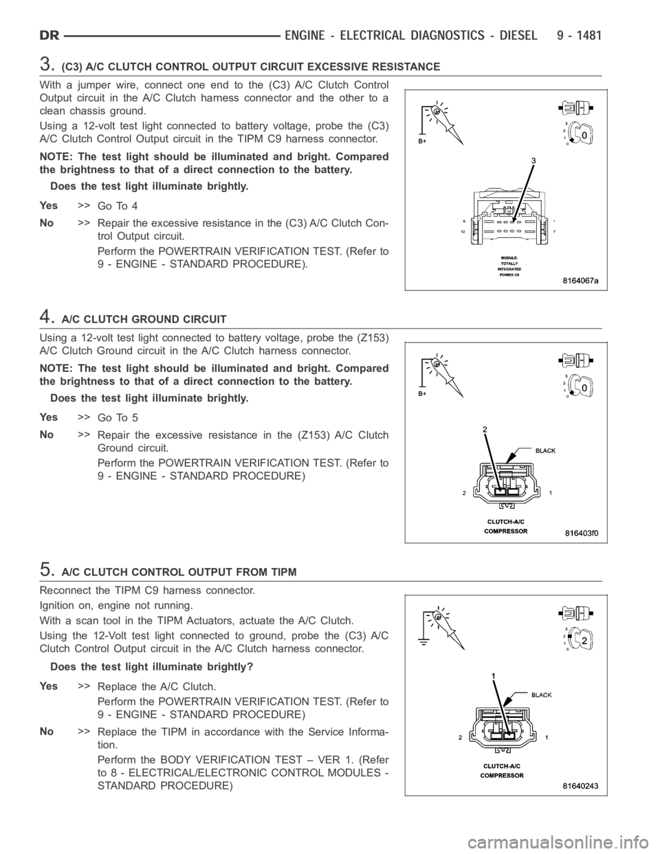
3.(C3) A/C CLUTCH CONTROL OUTPUT CIRCUIT EXCESSIVE RESISTANCE
With a jumper wire, connect one end to the (C3) A/C Clutch Control
Output circuit in the A/C Clutch harness connector and the other to a
clean chassis ground.
Using a 12-volt test light connected to battery voltage, probe the (C3)
A/C Clutch Control Output circuit in the TIPM C9 harness connector.
NOTE: The test light should be illuminated and bright. Compared
the brightness to that of a direct connection to the battery.
Does the test light illuminate brightly.
Ye s>>
Go To 4
No>>
Repair the excessive resistance in the (C3) A/C Clutch Con-
trol Output circuit.
Perform the POWERTRAIN VERIFICATION TEST. (Refer to
9 - ENGINE - STANDARD PROCEDURE).
4.A/C CLUTCH GROUND CIRCUIT
Using a 12-volt test light connected to battery voltage, probe the (Z153)
A/C Clutch Ground circuit in the A/C Clutch harness connector.
NOTE: The test light should be illuminated and bright. Compared
the brightness to that of a direct connection to the battery.
Does the test light illuminate brightly.
Ye s>>
Go To 5
No>>
Repair the excessive resistance in the (Z153) A/C Clutch
Ground circuit.
Perform the POWERTRAIN VERIFICATION TEST. (Refer to
9 - ENGINE - STANDARD PROCEDURE)
5.A/C CLUTCH CONTROL OUTPUT FROM TIPM
Reconnect the TIPM C9 harness connector.
Ignition on, engine not running.
With a scan tool in the TIPM Actuators, actuate the A/C Clutch.
Using the 12-Volt test light connected to ground, probe the (C3) A/C
Clutch Control Output circuit in the A/C Clutch harness connector.
Does the test light illuminate brightly?
Ye s>>
Replace the A/C Clutch.
Perform the POWERTRAIN VERIFICATION TEST. (Refer to
9 - ENGINE - STANDARD PROCEDURE)
No>>
Replace the TIPM in accordance with the Service Informa-
tion.
Perform the BODY VERIFICATION TEST – VER 1. (Refer
to 8 - ELECTRICAL/ELECTRONIC CONTROL MODULES -
STANDARD PROCEDURE)