Page 877 of 3171

CLUTCH PIPING
CL-13
D
E
F
G
H
I
J
K
L
MA
B
CL
CLUTCH PIPINGPFP:30650
Removal and InstallationECS00ICP
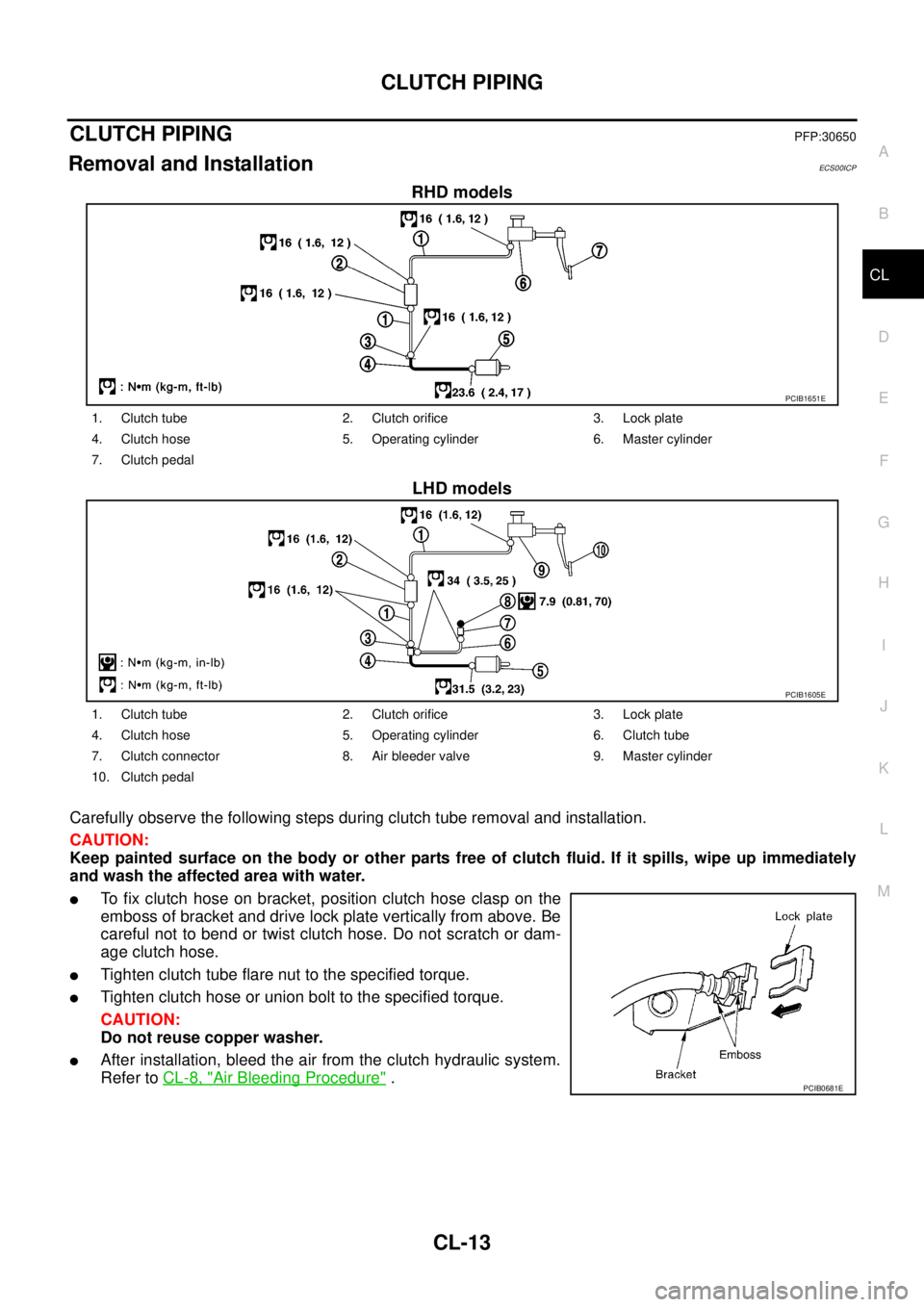
RHD models
LHD models
Carefully observe the following steps during clutch tube removal and installation.
CAUTION:
Keep painted surface on the body or other parts free of clutch fluid. If it spills, wipe up immediately
and wash the affected area with water.
lTo fix clutch hose on bracket, position clutch hose clasp on the
emboss of bracket and drive lock plate vertically from above. Be
careful not to bend or twist clutch hose. Do not scratch or dam-
age clutch hose.
lTighten clutch tube flare nut to the specified torque.
lTighten clutch hose or union bolt to the specified torque.
CAUTION:
Do not reuse copper washer.
lAfter installation, bleed the air from the clutch hydraulic system.
Refer toCL-8, "
Air Bleeding Procedure".
PCIB1651E
1. Clutch tube 2. Clutch orifice 3. Lock plate
4. Clutch hose 5. Operating cylinder 6. Master cylinder
7. Clutch pedal
PCIB1605E
1. Clutch tube 2. Clutch orifice 3. Lock plate
4. Clutch hose 5. Operating cylinder 6. Clutch tube
7. Clutch connector 8. Air bleeder valve 9. Master cylinder
10. Clutch pedal
PCIB0681E
Page 1281 of 3171

GLOW CONTROL SYSTEM
EC-301
C
D
E
F
G
H
I
J
K
L
MA
EC
15.CHECK INTERMITTENT INCIDENT
Refer toEC-70, "
TROUBLE DIAGNOSIS FOR INTERMITTENT INCIDENT".
>>INSPECTION END
Component InspectionEBS01KLP
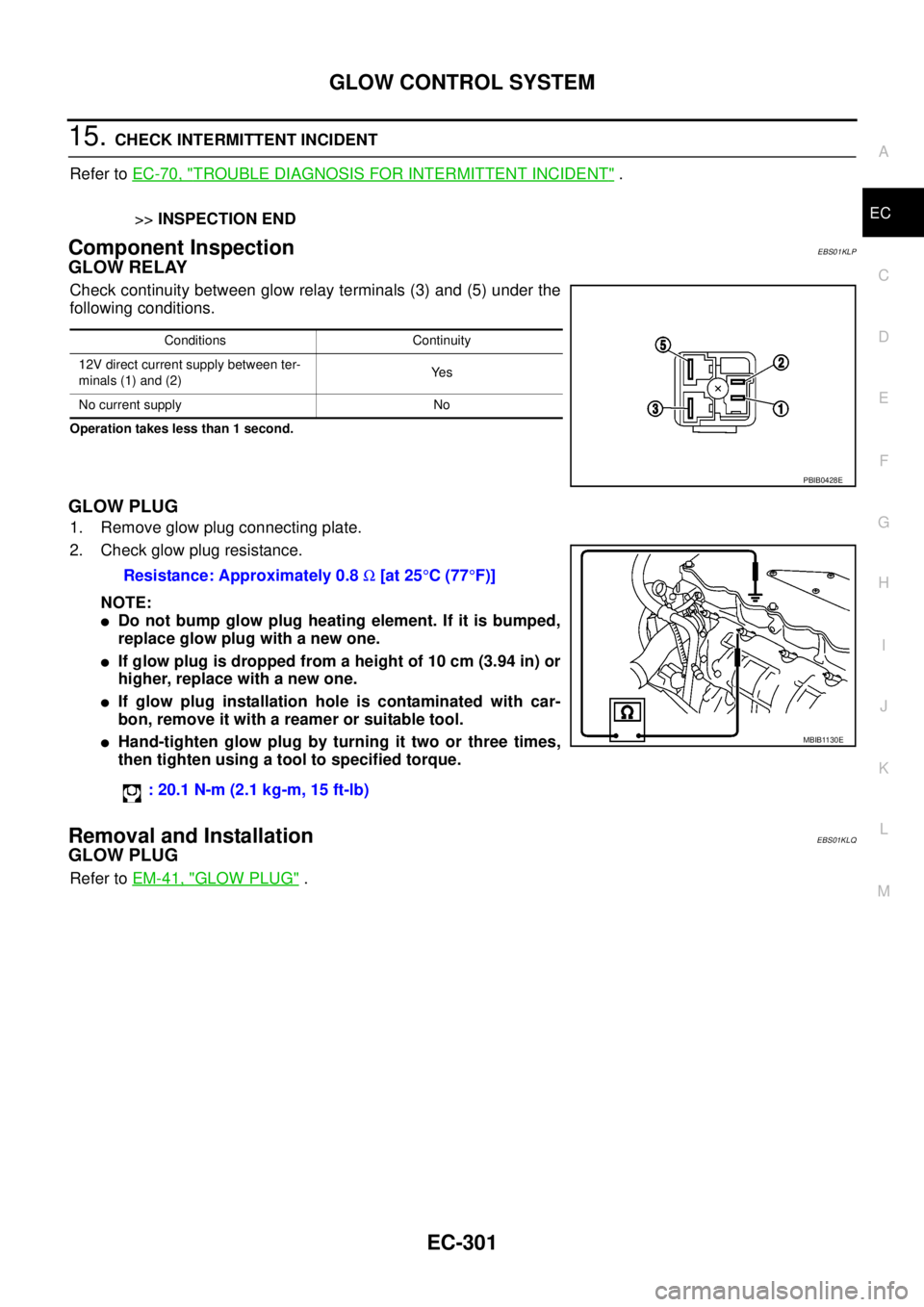
GLOW RELAY
Check continuity between glow relay terminals (3) and (5) under the
following conditions.
Operation takes less than 1 second.
GLOW PLUG
1. Remove glow plug connecting plate.
2. Check glow plug resistance.
NOTE:
lDo not bump glow plug heating element. If it is bumped,
replace glow plug with a new one.
lIf glow plug is dropped from a height of 10 cm (3.94 in) or
higher, replace with a new one.
lIf glow plug installation hole is contaminated with car-
bon, remove it with a reamer or suitable tool.
lHand-tighten glow plug by turning it two or three times,
then tighten using a tool to specified torque.
Removal and InstallationEBS01KLQ
GLOW PLUG
Refer toEM-41, "GLOW PLUG".
Conditions Continuity
12V direct current supply between ter-
minals (1) and (2)Ye s
No current supply No
PBIB0428E
Resistance: Approximately 0.8W[at 25°C(77°F)]
: 20.1 N-m (2.1 kg-m, 15 ft-lb)
MBIB1130E
Page 1386 of 3171

EM-4
PRECAUTIONS
PRECAUTIONS
PFP:00001
Precautions for Draining Engine CoolantEBS01E5H
Drain engine coolant when engine is cooled.
Precautions for Disconnecting Fuel PipingEBS01E5I
lBefore starting work, make sure no fire or spark producing items are in the work area.
lAfter disconnecting pipes, plug openings to stop fuel leakage.
Precautions for Removal and DisassemblyEBS01E5J
lWhen instructed to use SST, use the specified tools. Always be careful to work safely, avoid forceful or
uninstructed operations.
lExercise maximum care to avoid damage to mating or sliding surfaces.
lCover openings of engine system with tape or the equivalent, if necessary, to seal out foreign materials.
lMark and arrange disassembly parts in an organized way for easy troubleshooting and re-assembly.
lWhen loosening nuts and bolts, as a basic rule, start with the one furthest outside, then the one diagonally
opposite, and so on. If the order of loosening is specified, do exactly as specified.
Precautions for Inspection, Repair and ReplacementEBS01E5K
Before repairing or replacing, thoroughly inspect parts. Inspect new replacement parts in the same way, and
replace if necessary.
Precautions for Assembly and InstallationEBS01E5L
lUsetorquewrenchtotightenboltsornutstospecification.
lWhen tightening nuts and bolts, as a basic rule, equally tighten in several different steps starting with the
ones in center, then ones on inside and outside diagonally in this order. If the order of tightening is speci-
fied, do exactly as specified.
lReplace with new liquid gasket, packing, oil seal or O-ring.
lDowel pins are used for several parts alignment. When replacing and reassembling parts with dowel pins,
make sure that dowel pins are installed in the original position.
lThoroughly wash, clean, and air-blow each part. Carefully check engine oil or engine coolant passages for
any restriction and blockage.
lAvoid damaging sliding or mating surfaces. Completely remove foreign materials such as cloth lint or dust.
Before assembly, oil sliding surfaces well.
lRelease air within route when refilling after draining engine coolant.
lAfter repairing, start engine and increase engine speed to check engine coolant, fuel, engine oil, and
exhaust systems for leakage.
Parts Requiring Angle TighteningEBS01E5M
lUse an angle wrench [SST: KV10112100] for the final tightening of the following engine parts:
–Cylinder head bolts
–Main bearing cap bolts
–Connecting rod cap nuts
–Crankshaft pulley bolt (No angle wrench is required as the bolt flange is provided with notches for angle
tightening)
lDo not use a torque value for final tightening.
lThe torque value for these parts are for a preliminary step.
lEnsure thread and seat surfaces are clean and coated with engine oil.
Page 1396 of 3171
EM-14
DRIVE BELTS
A/C COMPRESSOR, ALTERNATOR AND WATER PUMP BELT
1. Loosen idler pulley lock nut (D).
2. Turn adjusting nut (C) to adjust. Refer toEM-13, "
Deflection Adjustment".
3. Tighten lock nut (D).
Removal and InstallationEBS01EJ6
REMOVAL
1. Loosen each belt. Refer toEM-13, "Deflection Adjustment".
2. Remove power steering oil pump belt. Refer toEM-13, "
POWER STEERING OIL PUMP BELT".
3. Remove A/C compressor, alternator and water pump belt. Refer toEM-14, "
A/C COMPRESSOR, ALTER-
NATOR AND WATER PUMP BELT".
INSTALLATION
1. Install each belt on pulley in the reverse order of removal.
2. Adjust belt deflection. Refer toEM-13, "
Deflection Adjustment".
3. Tighten nuts provided for adjustment to the specified torque.
4. Make sure again that each belt deflection is as specified.Nut D:
: 45.0 N·m (4.6 kg-m, 33 ft-lb)
Page 1404 of 3171
EM-22
INTAKE MANIFOLD
13. Loosen bolts and nuts in the reverse order of that shown in the
figure, and remove intake manifold.
CAUTION:
Cover engine openings to avoid entry of foreign materials.
14. Remove EGR volume control valve and throttle chamber from intake manifold.
INSPECTION AFTER REMOVAL
Surface Distortion
lCheck distortion on the mounting surface with a straightedge
and feeler gauge.
lIf it exceeds the limit, replace intake manifold.
INSTALLATION
Note the following, and install in the reverse order of removal.
lInstall intake manifold.
–Tighten fixing bolts and nuts in numerical order as shown in the
figure.
–If stud bolts were removed, tighten them to the specified torque.
lInstall EGR tube (M/T models).
–Tighten fixing bolts and nuts in numerical order as shown in the figure.
PBIC3410E
Limit : 0.1 mm (0.004 in)
PBIC3411E
: 10.8 N·m (1.1 kg-m, 8 ft-lb)
PBIC3410E
Page 1409 of 3171
CATALYST
EM-27
C
D
E
F
G
H
I
J
K
L
MA
EM
INSTALLATION
Note the following, and install in the reverse order of removal.
lIf stud bolts of turbocharger were removed, tighten them to the specified torque.
lIf stud bolts of catalyst were removed, tighten them to the specified torque.
lPushing bracket against the cylinder block and the catalyst, temporarily tighten the mounting bolt. And
then tighten it to the specified torque.: 25.5 N·m (2.6 kg-m, 19 ft-lb)
: 45.0 N·m (4.6 kg-m, 33 ft-lb)
Page 1415 of 3171
TURBO CHARGER
EM-33
C
D
E
F
G
H
I
J
K
L
MA
EM
INSTALLATION
Note the following, and install in the reverse order of removal.
lWhen a stud bolt is pulled out, replace it with a new one and tighten it to the following torque.
: 25.5 N·m (2.6 kg-m, 19 ft-lb)
Page 1417 of 3171

EXHAUST MANIFOLD
EM-35
C
D
E
F
G
H
I
J
K
L
MA
EM
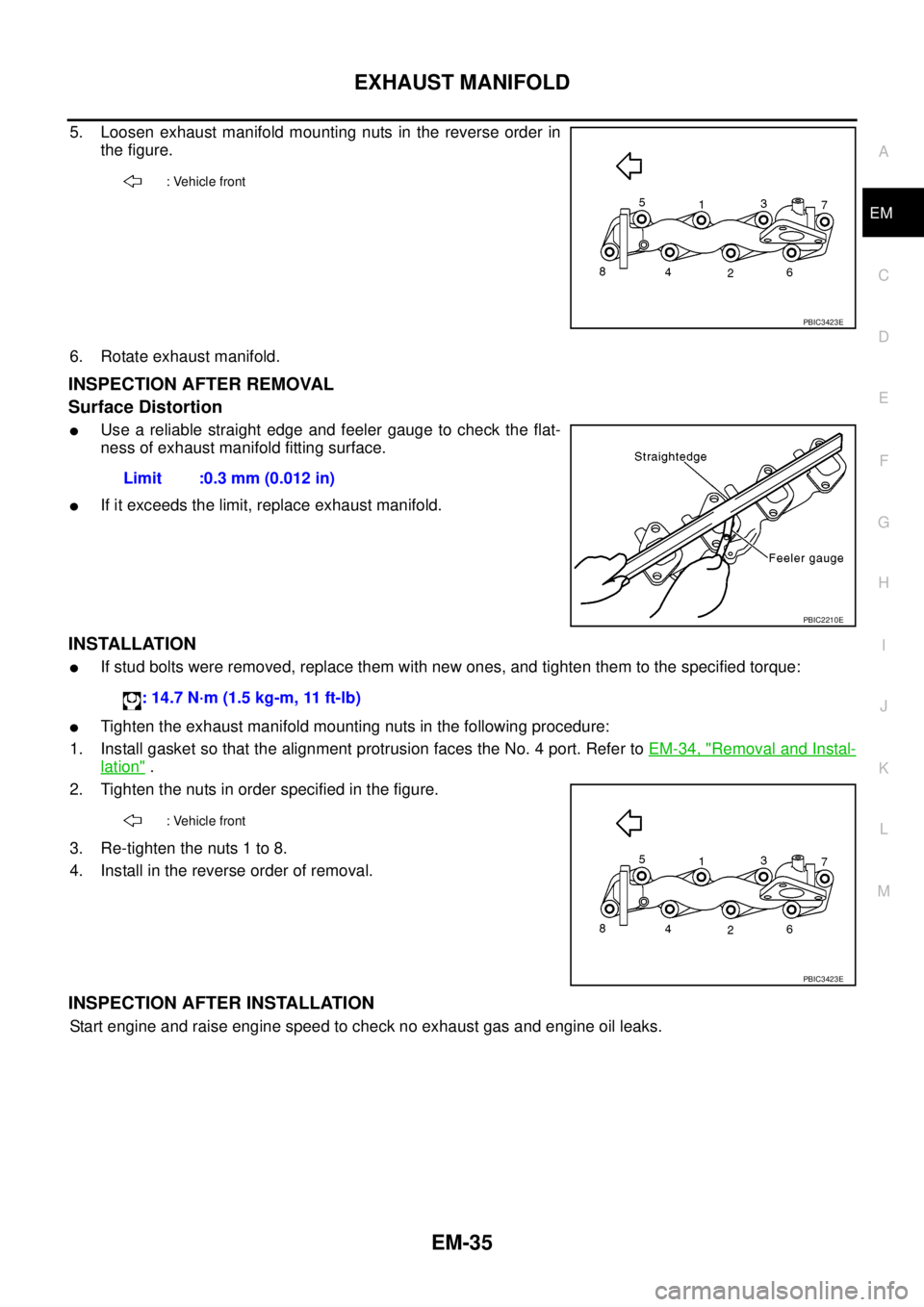
5. Loosen exhaust manifold mounting nuts in the reverse order in
the figure.
6. Rotate exhaust manifold.
INSPECTION AFTER REMOVAL
Surface Distortion
lUse a reliable straight edge and feeler gauge to check the flat-
ness of exhaust manifold fitting surface.
lIf it exceeds the limit, replace exhaust manifold.
INSTALLATION
lIf stud bolts were removed, replace them with new ones, and tighten them to the specified torque:
lTighten the exhaust manifold mounting nuts in the following procedure:
1. Install gasket so that the alignment protrusion faces the No. 4 port. Refer toEM-34, "
Removal and Instal-
lation".
2. Tighten the nuts in order specified in the figure.
3. Re-tighten the nuts 1 to 8.
4. Install in the reverse order of removal.
INSPECTION AFTER INSTALLATION
Start engine and raise engine speed to check no exhaust gas and engine oil leaks.
: Vehicle front
PBIC3423E
Limit :0.3 mm (0.012 in)
PBIC2210E
: 14.7 N·m (1.5 kg-m, 11 ft-lb)
: Vehicle front
PBIC3423E