2005 NISSAN NAVARA torque
[x] Cancel search: torquePage 812 of 3171

BR-26
FRONT DISC BRAKE
Removal and Installation of Brake Caliper Assembly
EFS005T1
REMOVAL
1. Remove tyre from vehicle.
2. Fasten disc rotor using wheel nut.
CAUTION:
Align the matching marks of disc rotor and wheel hub, which were marked at the time of removal
when reusing disc rotor.
3. Drain brake fluid. Refer toBR-10, "
Drain and Refill".
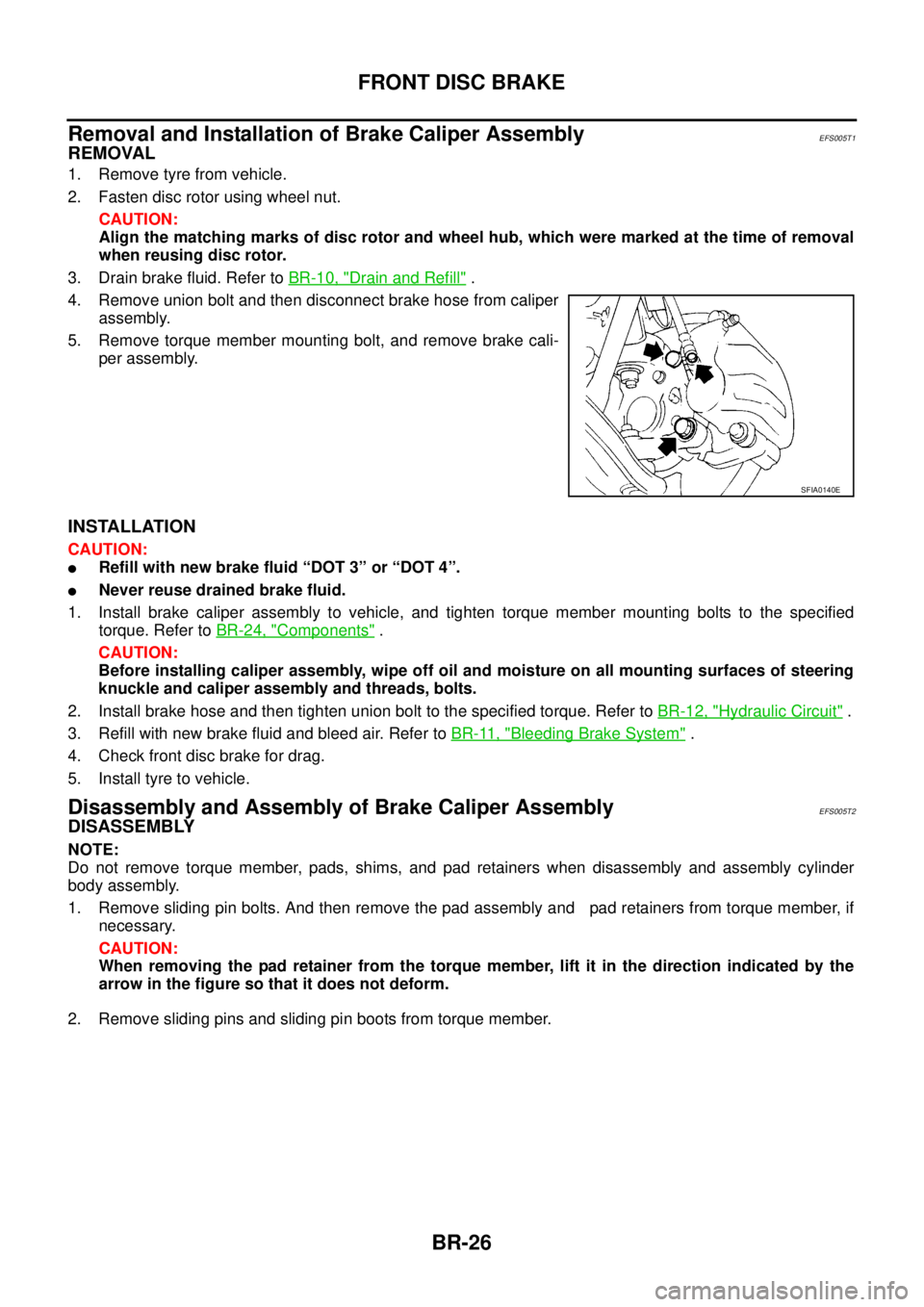
4. Remove union bolt and then disconnect brake hose from caliper
assembly.
5. Remove torque member mounting bolt, and remove brake cali-
per assembly.
INSTALLATION
CAUTION:
lRefill with new brake fluid “DOT 3” or “DOT 4”.
lNever reuse drained brake fluid.
1. Install brake caliper assembly to vehicle, and tighten torque member mounting bolts to the specified
torque. Refer toBR-24, "
Components".
CAUTION:
Before installing caliper assembly, wipe off oil and moisture on all mounting surfaces of steering
knuckle and caliper assembly and threads, bolts.
2. Install brake hose and then tighten union bolt to the specified torque. Refer toBR-12, "
Hydraulic Circuit".
3. Refill with new brake fluid and bleed air. Refer toBR-11, "
Bleeding Brake System".
4. Check front disc brake for drag.
5. Install tyre to vehicle.
Disassembly and Assembly of Brake Caliper AssemblyEFS005T2
DISASSEMBLY
NOTE:
Do not remove torque member, pads, shims, and pad retainers when disassembly and assembly cylinder
body assembly.
1. Remove sliding pin bolts. And then remove the pad assembly and pad retainers from torque member, if
necessary.
CAUTION:
When removing the pad retainer from the torque member, lift it in the direction indicated by the
arrow in the figure so that it does not deform.
2. Remove sliding pins and sliding pin boots from torque member.
SFIA0140E
Page 813 of 3171

FRONT DISC BRAKE
BR-27
C
D
E
G
H
I
J
K
L
MA
B
BR
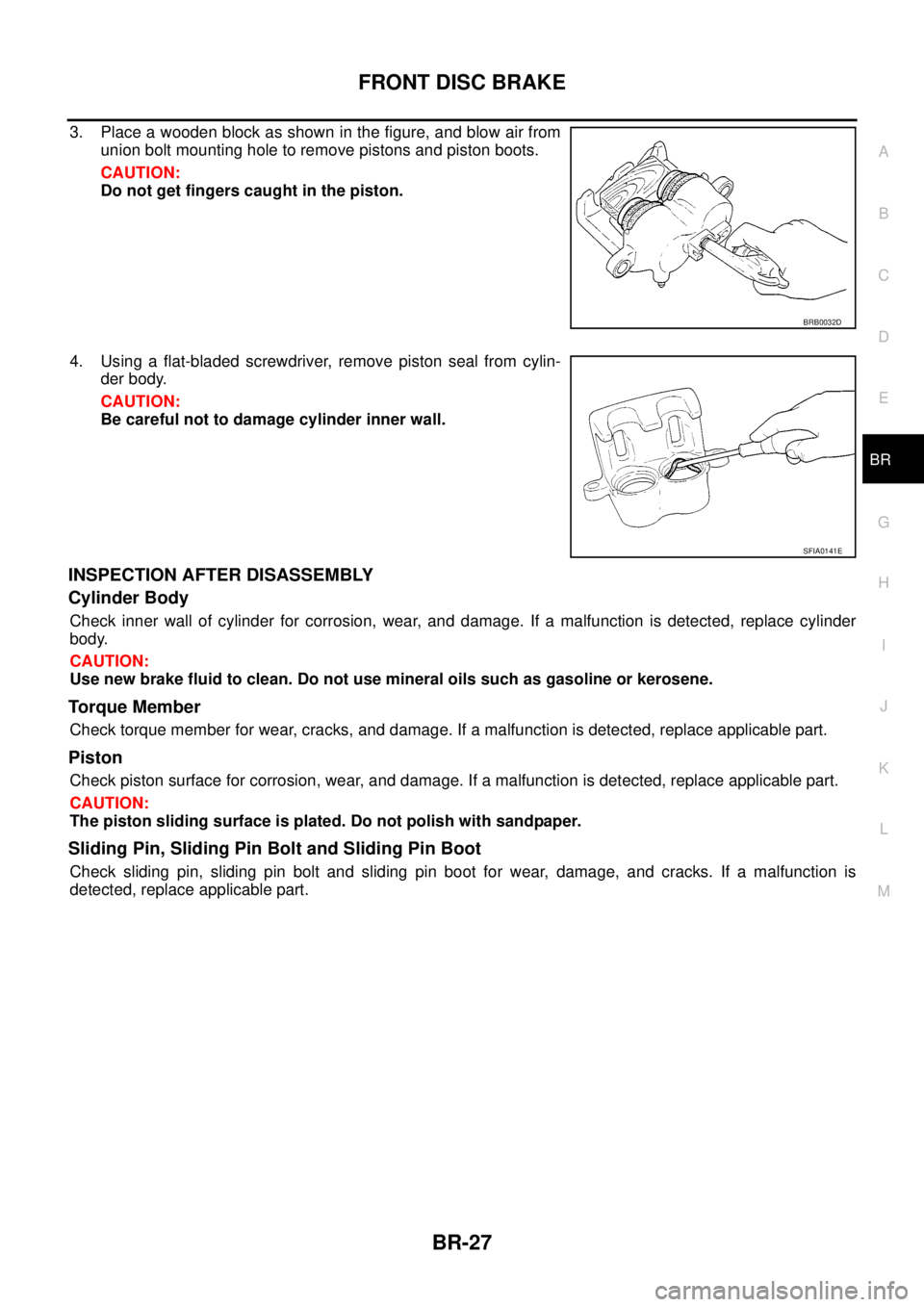
3. Place a wooden block as shown in the figure, and blow air from
union bolt mounting hole to remove pistons and piston boots.
CAUTION:
Do not get fingers caught in the piston.
4. Using a flat-bladed screwdriver, remove piston seal from cylin-
der body.
CAUTION:
Be careful not to damage cylinder inner wall.
INSPECTION AFTER DISASSEMBLY
Cylinder Body
Check inner wall of cylinder for corrosion, wear, and damage. If a malfunction is detected, replace cylinder
body.
CAUTION:
Use new brake fluid to clean. Do not use mineral oils such as gasoline or kerosene.
Torque Member
Check torque member for wear, cracks, and damage. If a malfunction is detected, replace applicable part.
Piston
Check piston surface for corrosion, wear, and damage. If a malfunction is detected, replace applicable part.
CAUTION:
The piston sliding surface is plated. Do not polish with sandpaper.
Sliding Pin, Sliding Pin Bolt and Sliding Pin Boot
Check sliding pin, sliding pin bolt and sliding pin boot for wear, damage, and cracks. If a malfunction is
detected, replace applicable part.
BRB0032D
SFIA0141E
Page 814 of 3171

BR-28
FRONT DISC BRAKE
ASSEMBLY
CAUTION:
When assembling, use only rubber lubricant specified below.
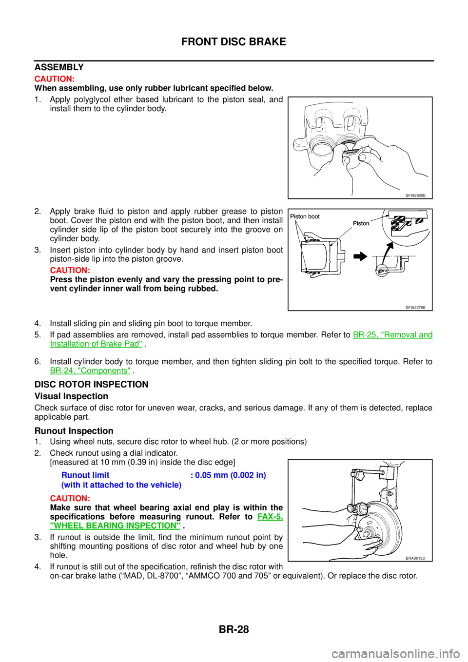
1. Apply polyglycol ether based lubricant to the piston seal, and
install them to the cylinder body.
2. Apply brake fluid to piston and apply rubber grease to piston
boot.Coverthepistonendwiththepistonboot,andtheninstall
cylinder side lip of the piston boot securely into the groove on
cylinder body.
3. Insert piston into cylinder body by hand and insert piston boot
piston-side lip into the piston groove.
CAUTION:
Press the piston evenly and vary the pressing point to pre-
vent cylinder inner wall from being rubbed.
4. Install sliding pin and sliding pin boot to torque member.
5. If pad assemblies are removed, install pad assemblies to torque member. Refer toBR-25, "
Removal and
Installation of Brake Pad".
6. Install cylinder body to torque member, and then tighten sliding pin bolt to the specified torque. Refer to
BR-24, "
Components".
DISC ROTOR INSPECTION
Visual Inspection
Check surface of disc rotor for uneven wear, cracks, and serious damage. If any of them is detected, replace
applicable part.
Runout Inspection
1. Using wheel nuts, secure disc rotor to wheel hub. (2 or more positions)
2. Check runout using a dial indicator.
[measured at 10 mm (0.39 in) inside the disc edge]
CAUTION:
Make sure that wheel bearing axial end play is within the
specifications before measuring runout. Refer toFAX-5,
"WHEEL BEARING INSPECTION".
3. If runout is outside the limit, find the minimum runout point by
shifting mounting positions of disc rotor and wheel hub by one
hole.
4. If runout is still out of the specification, refinish the disc rotor with
on-car brake lathe (“MAD, DL-8700”, “AMMCO 700 and 705” or equivalent). Or replace the disc rotor.
SFIA2920E
SFIA2279E
Runout limit
(with it attached to the vehicle):0.05mm(0.002in)
BRA0013D
Page 820 of 3171

BR-34
REAR DRUM BRAKE
Removal and Installation of Wheel Cylinder
EFS006AH
REMOVAL
1. Drain brake fluid. Refer toBR-10, "Drain and Refill".
2. Remove rear brake shoe assembly.
3. Remove brake tube from the wheel cylinder.
4. Remove bolts on the wheel cylinder, and then remove wheel cylinder from the back plate.
INSTALLATION
lInstallation is the reverse order of removal. Tighten bolts to the specified torque. Refer toBR-30, "Compo-
nents".
lRefill with new brake fluid and bleed air. Refer toBR-11, "Bleeding Brake System".
Disassembly and Assembly of Wheel CylinderEFS006AI
DISASSEMBLY
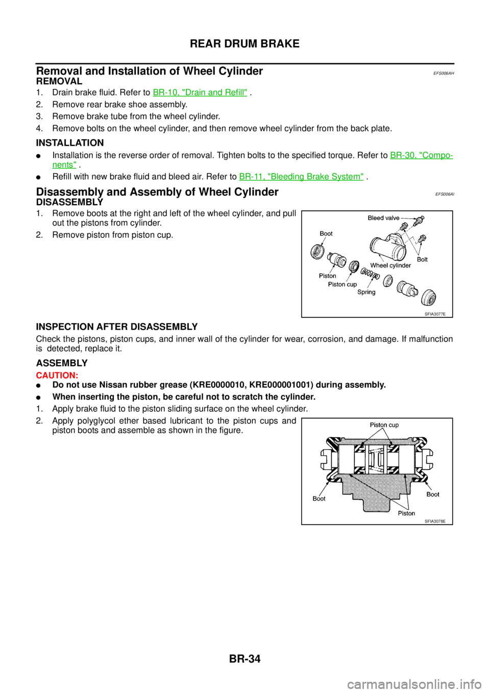
1. Remove boots at the right and left of the wheel cylinder, and pull
out the pistons from cylinder.
2. Remove piston from piston cup.
INSPECTION AFTER DISASSEMBLY
Check the pistons, piston cups, and inner wall of the cylinder for wear, corrosion, and damage. If malfunction
is detected, replace it.
ASSEMBLY
CAUTION:
lDo not use Nissan rubber grease (KRE0000010, KRE000001001) during assembly.
lWhen inserting the piston, be careful not to scratch the cylinder.
1. Apply brake fluid to the piston sliding surface on the wheel cylinder.
2. Apply polyglycol ether based lubricant to the piston cups and
piston boots and assemble as shown in the figure.
SFIA3077E
SFIA3078E
Page 825 of 3171
![NISSAN NAVARA 2005 Repair Workshop Manual PRECAUTIONS
BRC-3
[ABS]
C
D
E
G
H
I
J
K
L
MA
B
BRC
[ABS]PRECAUTIONSPFP:00001
Precautions for Supplemental Restraint System (SRS) “AIR BAG” and “SEAT
BELT PRE-TENSIONER”
EFS006DM
The Supplement NISSAN NAVARA 2005 Repair Workshop Manual PRECAUTIONS
BRC-3
[ABS]
C
D
E
G
H
I
J
K
L
MA
B
BRC
[ABS]PRECAUTIONSPFP:00001
Precautions for Supplemental Restraint System (SRS) “AIR BAG” and “SEAT
BELT PRE-TENSIONER”
EFS006DM
The Supplement](/manual-img/5/57362/w960_57362-824.png)
PRECAUTIONS
BRC-3
[ABS]
C
D
E
G
H
I
J
K
L
MA
B
BRC
[ABS]PRECAUTIONSPFP:00001
Precautions for Supplemental Restraint System (SRS) “AIR BAG” and “SEAT
BELT PRE-TENSIONER”
EFS006DM
The Supplemental Restraint System such as “AIR BAG” and “SEAT BELT PRE-TENSIONER”, used along
with a front seat belt, helps to reduce the risk or severity of injury to the driver and front passenger for certain
types of collision. Information necessary to service the system safely is included in the SRS and SB section of
this Service Manual.
WARNING:
lTo avoid rendering the SRS inoperative, which could increase the risk of personal injury or death
in the event of a collision which would result in air bag inflation, all maintenance must be per-
formed by an authorized NISSAN/INFINITI dealer.
lImproper maintenance, including incorrect removal and installation of the SRS, can lead to per-
sonal injury caused by unintentional activation of the system. For removal of Spiral Cable and Air
Bag Module, see the SRS section.
lDo not use electrical test equipment on any circuit related to the SRS unless instructed to in this
Service Manual. SRS wiring harnesses can be identified by yellow and/or orange harnesses or
harness connectors.
Precautions for Brake SystemEFS005TG
lRecommended fluid is brake fluid “DOT 3” or “DOT 4”.
lNever reuse drained brake fluid.
lBe careful not to splash brake fluid on painted areas.If brake fluid is splashed, wipe it off and flush area
with water immediately.
lNever use mineral oils such as gasoline or kerosene. They will ruin rubber parts of the hydraulic system.
lUse flare nut wrench when removing flare nuts, and use a flare
nut torque wrench when tighten flare nuts.
lBrake system is an important safety part.If a brake fluid leak is
detected, always disassemble the affected part.If a malfunction
is detected, replace part with new one.
lBefore working, turn ignition switch OFF and disconnect con-
nector of ABS actuator and electric unit (control unit) or the bat-
tery cables.
lWhen installing brake tube and hose, be sure to torque.
WARNING:
Clean brake pads and shoes with a waster cloth, then wipe with
a dust collector.
Precautions for Brake ControlEFS005TH
lJust after starting vehicle after ignition switch ON, brake pedal may vibrate or motor operating noise may
be heard from engine room. This is a normal status of operation check.
lStopping distance may be longer than that of vehicles without ABS when vehicle drives on rough, gravel,
or snow-covered (fresh, deep snow) roads.
lWhen an error is indicated by ABS or another warning lamp, collect all necessary information from cus-
tomer (what symptoms are present under what conditions) and check for simple causes before starting
diagnostic servicing. Besides electrical system inspection, check brake booster operation, brake fluid
level, and fluid leaks.
lIf tyre size and type are used in an improper combination, or brake pads are not Genuine NISSAN parts,
stopping distance or steering stability may deteriorate.
lIf there is a radio, antenna, or antenna lead-in wire (including wiring) near control module, ABS function
may have a malfunction or error.
lIf aftermarket parts (car stereo, CD player, etc.) have been installed, check for incidents such as harness
pinches, open circuits, and improper wiring.
SBR820BA
Page 826 of 3171
![NISSAN NAVARA 2005 Repair Workshop Manual BRC-4
[ABS]
PREPARATION
PREPARATION
PFP:00002
Special Service Tools (SST)EFS005TI
Tool number
Tool nameDescription
GG94310000
Flare nut torque wrench
a:10 mm (0.39 in)Installing brake tube and hose
ST NISSAN NAVARA 2005 Repair Workshop Manual BRC-4
[ABS]
PREPARATION
PREPARATION
PFP:00002
Special Service Tools (SST)EFS005TI
Tool number
Tool nameDescription
GG94310000
Flare nut torque wrench
a:10 mm (0.39 in)Installing brake tube and hose
ST](/manual-img/5/57362/w960_57362-825.png)
BRC-4
[ABS]
PREPARATION
PREPARATION
PFP:00002
Special Service Tools (SST)EFS005TI
Tool number
Tool nameDescription
GG94310000
Flare nut torque wrench
a:10 mm (0.39 in)Installing brake tube and hose
ST30720000
Drift
a: 77 mm (0.03 in) dia.
b: 55 mm (2.17 in) dia.
Installation rear sensor rotor ST27863000
Drift
a: 75 mm (2.95 in) dia.
b: 62 mm (2.44 in) dia.
KV40104710
Drift
a: 76 mm (2.99 in) dia.
b: 68.5 mm (2.697 in) dia.
NT406
ZZA0701D
ZZA0832D
ZZA0832D
Page 845 of 3171
![NISSAN NAVARA 2005 Repair Workshop Manual TROUBLE DIAGNOSIS
BRC-23
[ABS]
C
D
E
G
H
I
J
K
L
MA
B
BRC
For Fast and Accurate DiagnosisEFS005TX
PRECAUTIONS FOR DIAGNOSIS
lBefore performing diagnosis, always read precautions. Refer toBRC-17, "CONS NISSAN NAVARA 2005 Repair Workshop Manual TROUBLE DIAGNOSIS
BRC-23
[ABS]
C
D
E
G
H
I
J
K
L
MA
B
BRC
For Fast and Accurate DiagnosisEFS005TX
PRECAUTIONS FOR DIAGNOSIS
lBefore performing diagnosis, always read precautions. Refer toBRC-17, "CONS](/manual-img/5/57362/w960_57362-844.png)
TROUBLE DIAGNOSIS
BRC-23
[ABS]
C
D
E
G
H
I
J
K
L
MA
B
BRC
For Fast and Accurate DiagnosisEFS005TX
PRECAUTIONS FOR DIAGNOSIS
lBefore performing diagnosis, always read precautions. Refer toBRC-17, "CONSULT- II Functions".
lAfter diagnosis is finished, be sure to erase memory. Refer toBRC-18, "ERASE MEMORY".
lWhen checking continuity and voltage between units, be sure to check for disconnection, looseness,
bend, or collapse of connector terminals. If any malfunction is found, repair or replace connector termi-
nals.
lFor intermittent symptoms, possible cause is malfunction in harness, harness connector, or terminals.
Move harness, harness connector, and terminals to check for poor connections.
lIf a circuit tester is used for check, be careful not to forcibly extend any connector terminal.
lABS system electrically controls brake operation and engine output. Following symptoms may be caused
by normal operations:
Basic InspectionEFS005TY
BASIC INSPECTION 1 BRAKE FLUID LEVEL, LEAKS, AND BRAKE PADS
1. Check fluid level in the brake reservoir tank. If fluid level is low, refill brake fluid.
2. Check brake tube and around ABS actuator and electric unit (control unit) for leaks. If leakage or seepage
is found, check the following items.
lIf ABS actuator and electric unit (control unit) connection is loose, tighten brake tube to the specified
torque and re-conduct the leak inspection to make sure there are no leakage.
lIf there is damage to the connection flare nut or ABS actuator and electric unit (control unit) screw,
replace the damaged part and re-conduct the leak inspection to make sure there are no leakage.
lIf there is leakage or seepage at any location other than ABS actuator and electric unit (control unit)
connection, wipe away leakage or seepage with clean cloth. Then inspect again and confirm than there
is on leakage.
lIf there is leakage from ABS actuator and electric unit (control unit), wipe away leakage or seepage with
clean cloth. Then inspect again. If there is leakage or seepage, replace ABS actuator and electric unit
(control unit).
CAUTION:
ABS actuator and electric unit (control unit) body cannot be disassembled.
3. Check brake pad degree of wear. Refer toBR-24, "
PAD WEAR INSPECTION"in “Front Disc Brake” and
BR-32, "
Lining Thickness Inspection"in “Rear Drum Brake”.
BASIC INSPECTION 2 POWER SYSTEM TERMINAL LOOSENESS AND BATTERY INSPECTION
Make sure battery positive cable, negative cable and ground connection are not loose. In addition, check the
battery voltage to make sure it has not dropped and alternator is normal.
Symptom Symptom description Result
Motor operation noiseThis is noise of motor inside ABS actuator and electric unit (control unit). Slight
noise may occur during ABS operation.
Normal
Just after engine starts, motor operating noise may be heard. This is a normal
status of the system operation check.
System operation check noiseWhen engine starts, slight “click” noise may be heard from engine compart-
ment. This is normal and is part of system operation check.Normal
ABS operation
(Longer stopping distance)When driving on roads with a low coefficient of friction, such as snowy roads
or gravel roads, the stopping distance is sometimes longer for vehicles
equipped with ABS. Therefore, when driving on such roads, drive at a suffi-
ciently reduced speed to be safe.Normal
Page 860 of 3171
![NISSAN NAVARA 2005 Repair Workshop Manual BRC-38
[ABS]
WHEEL SENSORS
REMOVAL
Pay attention to the following when removing wheel sensor.
CAUTION:
lAs much as possible, avoid rotating wheel sensor when removing it. Pull wheel sensors out with-
NISSAN NAVARA 2005 Repair Workshop Manual BRC-38
[ABS]
WHEEL SENSORS
REMOVAL
Pay attention to the following when removing wheel sensor.
CAUTION:
lAs much as possible, avoid rotating wheel sensor when removing it. Pull wheel sensors out with-](/manual-img/5/57362/w960_57362-859.png)
BRC-38
[ABS]
WHEEL SENSORS
REMOVAL
Pay attention to the following when removing wheel sensor.
CAUTION:
lAs much as possible, avoid rotating wheel sensor when removing it. Pull wheel sensors out with-
out pulling on sensor harness.
lTake care to avoid damaging wheel sensor edges or rotor teeth. Remove wheel sensor first before
removing front or rear wheel hub. This is to avoid damage to wheel sensor wiring and loss of sen-
sor function.
INSTALLATION
Pay attention to the following when installing wheel sensor. Tighten installation bolts and nuts to the specified
torques.
lWhen installing, make sure there is no foreign material such as iron chips on and in the mounting hole of
the wheel sensor. Make sure no foreign material has been caught in the sensor rotor. Remove any foreign
material and clean the mount.
lWhen installing wheel sensor, be sure to press rubber grommets in until they lock at locations shown
above in figure. When installed, harness must not be twisted.