Page 862 of 3171
![NISSAN NAVARA 2005 Repair Workshop Manual BRC-40
[ABS]
ACTUATOR AND ELECTRIC UNIT (ASSEMBLY)
ACTUATOR AND ELECTRIC UNIT (ASSEMBLY)
PFP:47660
Removal and InstallationEFS005UG
CAUTION:
lBefore servicing, disconnect battery cables.
lTo remove br NISSAN NAVARA 2005 Repair Workshop Manual BRC-40
[ABS]
ACTUATOR AND ELECTRIC UNIT (ASSEMBLY)
ACTUATOR AND ELECTRIC UNIT (ASSEMBLY)
PFP:47660
Removal and InstallationEFS005UG
CAUTION:
lBefore servicing, disconnect battery cables.
lTo remove br](/manual-img/5/57362/w960_57362-861.png)
BRC-40
[ABS]
ACTUATOR AND ELECTRIC UNIT (ASSEMBLY)
ACTUATOR AND ELECTRIC UNIT (ASSEMBLY)
PFP:47660
Removal and InstallationEFS005UG
CAUTION:
lBefore servicing, disconnect battery cables.
lTo remove brake tube, use flare nut wrench to prevent flare nuts and brake tube from being dam-
aged. To install, use flare nut torque wrench.
lDo not apply excessive impact to ABS actuator and electric unit (control unit), such as dropping it.
lDo not remove and install actuator by holding harness.
lAfter work is completed, bleed air from brake tube and hose. Refer toBR-11, "Bleeding Brake Sys-
tem".
REMOVAL
1. Disconnect ABS actuator and electric unit (control unit) connector.
2. Loosen brake tube flare nuts, then remove brake tubes from ABS actuator and electric unit (control unit).
3. Remove ABS actuator and electric unit (control unit) bracket mounting bolts.
4. Remove ABS actuator and electric unit (control unit) from vehicle.
1. To rear 2. From master cylinder secondary
side3. To front left
4. From master cylinder primary side 5. To front right 6. ABS actuator and electric unit (con-
trol unit)
7. Harness connector
Refer to GI section for symbol marks in the figure.
SFIA3016E
Page 867 of 3171
PREPARATION
CL-3
D
E
F
G
H
I
J
K
L
MA
B
CL
PREPARATIONPFP:00002
Special Service ToolsECS00ICD
Commercial Service ToolsECS00ICE
Tool number
Tool nameDescription
KV30101400
Drift
a: 51 mm (2.01 in) dia.
b: 44 mm (1.73 in) dia.Installing release bearing
ST20050240
Diaphragm adjusting wrenchAdjusting unevenness of diaphragm spring of
clutch cover
KV30100100
Clutch aligning bar
a: 15.7 mm (0.618 in) dia.
b: 22.8 mm (0.898 in) dia.Installing clutch disc
ZZA0838D
ZZA0508D
ZZA1178D
Tool nameDescription
Pin punch
Tip diameter: 4.5 mm (0.177 in) dia.Removing and installing master cylinder
spring pin
GG94310000
Flare nut torque wrench
a: 10 mm (0.39 in)Removing and installing clutch piping
ZZA0515D
S-NT406
Page 868 of 3171
CL-4
PREPARATION
Flare nut torque wrench
a: 14 mm (0.55 in)Removing and installing clutch piping (For
LHD models)
PullerRemoving release bearing Tool nameDescription
S-NT406
NT077
Page 871 of 3171
CLUTCH PEDAL
CL-7
D
E
F
G
H
I
J
K
L
MA
B
CL
Removal and InstallationECS00ICH
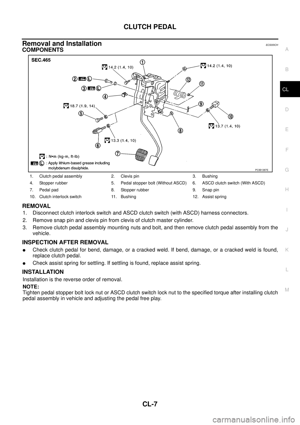
COMPONENTS
REMOVAL
1. Disconnect clutch interlock switch and ASCD clutch switch (with ASCD) harness connectors.
2. Remove snap pin and clevis pin from clevis of clutch master cylinder.
3. Remove clutch pedal assembly mounting nuts and bolt, and then remove clutch pedal assembly from the
vehicle.
INSPECTION AFTER REMOVAL
lCheck clutch pedal for bend, damage, or a cracked weld. If bend, damage, or a cracked weld is found,
replace clutch pedal.
lCheck assist spring for settling. If settling is found, replace assist spring.
INSTALLATION
Installation is the reverse order of removal.
NOTE:
Tighten pedal stopper bolt lock nut or ASCD clutch switch lock nut to the specified torque after installing clutch
pedal assembly in vehicle and adjusting the pedal free play.
1. Clutch pedal assembly 2. Clevis pin 3. Bushing
4. Stopper rubber 5. Pedal stopper bolt (Without ASCD) 6. ASCD clutch switch (With ASCD)
7. Pedal pad 8. Stopper rubber 9. Snap pin
10. Clutch interlock switch 11. Bushing 12. Assist spring
PCIB1387E
Page 872 of 3171
CL-8
CLUTCH FLUID
CLUTCH FLUID
PFP:00017
Air Bleeding ProcedureECS00ICI
NOTE:
Do not use a vacuum assist or any other type of power bleeder on this system. Use of a vacuum assist or
power bleeder will not purge all the air from the system.
CAUTION:
lMonitor clutch fluid level in reservoir tank to make sure it
does not empty.
lKeep painted surface on the body or other parts free of
clutch fluid. If it spills, wipe up immediately and wash the
affected area with water.
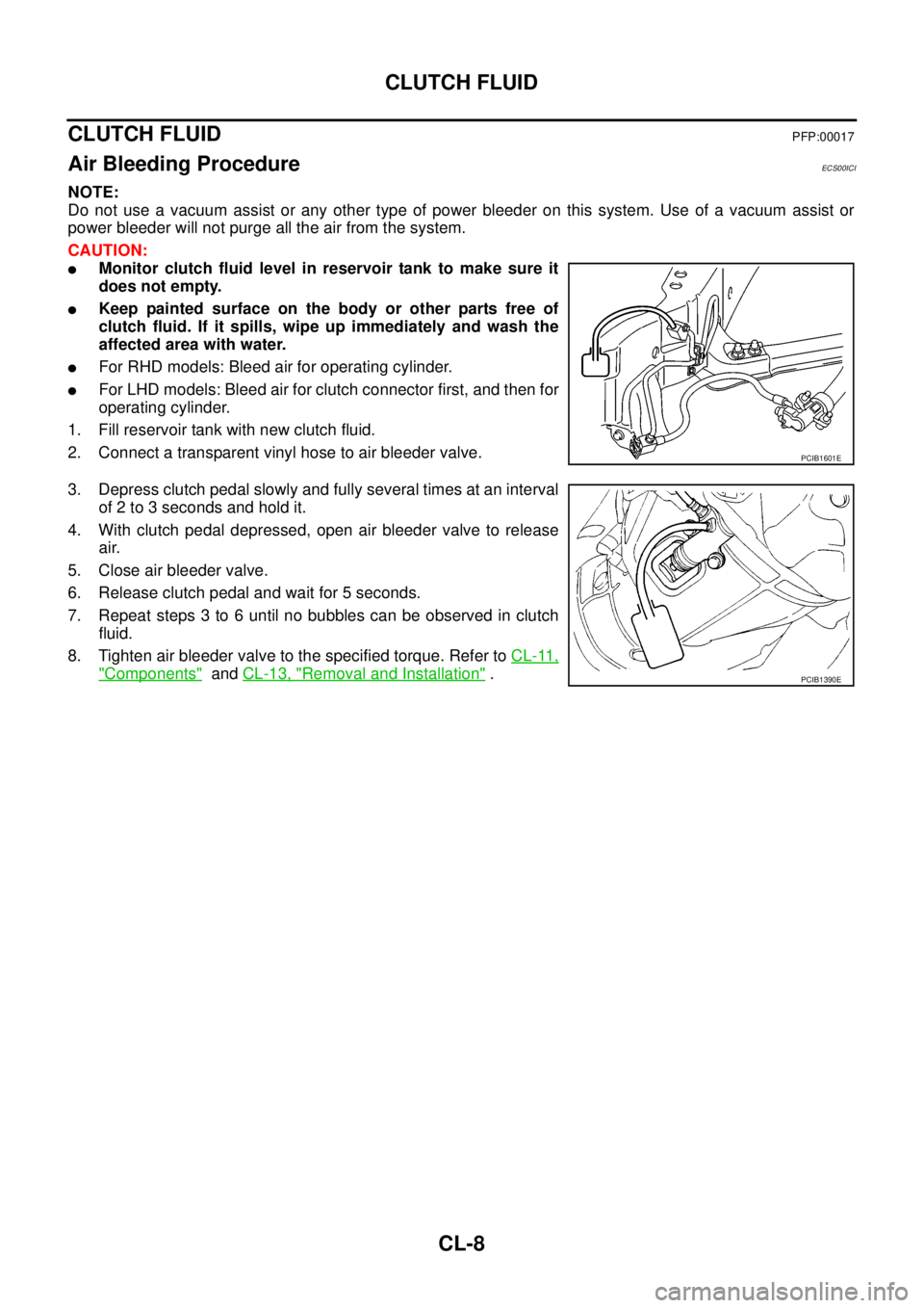
lFor RHD models: Bleed air for operating cylinder.
lFor LHD models: Bleed air for clutch connector first, and then for
operating cylinder.
1. Fill reservoir tank with new clutch fluid.
2. Connect a transparent vinyl hose to air bleeder valve.
3. Depress clutch pedal slowly and fully several times at an interval
of 2 to 3 seconds and hold it.
4. With clutch pedal depressed, open air bleeder valve to release
air.
5. Close air bleeder valve.
6. Release clutch pedal and wait for 5 seconds.
7. Repeat steps 3 to 6 until no bubbles can be observed in clutch
fluid.
8. Tighten air bleeder valve to the specified torque. Refer toCL-11,
"Components"andCL-13, "Removal and Installation".
PCIB1601E
PCIB1390E
Page 873 of 3171
CLUTCH MASTER CYLINDER
CL-9
D
E
F
G
H
I
J
K
L
MA
B
CL
CLUTCH MASTER CYLINDERPFP:30610
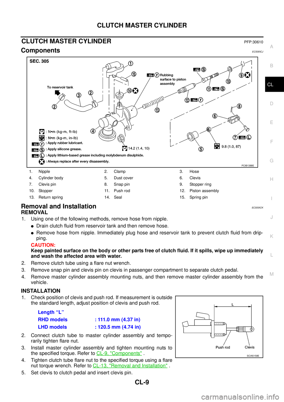
ComponentsECS00ICJ
Removal and InstallationECS00ICK
REMOVAL
1. Using one of the following methods, remove hose from nipple.
lDrain clutch fluid from reservoir tank and then remove hose.
lRemove hose from nipple. Immediately plug hose and reservoir tank to prevent clutch fluid from drip-
ping.
CAUTION:
Keep painted surface on the body or other parts free of clutch fluid. If it spills, wipe up immediately
and wash the affected area with water.
2. Remove clutch tube using a flare nut wrench.
3. Remove snap pin and clevis pin on clevis in passenger compartment to separate clutch pedal.
4. Remove master cylinder assembly mounting nuts, and then remove master cylinder assembly from the
vehicle.
INSTALLATION
1. Check position of clevis and push rod. If measurement is outside
the standard length, adjust position of clevis and push rod.
2. Connect clutch tube to master cylinder assembly and tempo-
rarily tighten flare nut.
3. Install master cylinder assembly and tighten mounting nuts to
the specified torque. Refer toCL-9, "
Components".
4. Tightenclutchtubeflarenuttothespecifiedtorqueusingaflare
nut torque wrench. Refer toCL-13, "
Removal and Installation".
5. Set clevis to clutch pedal and insert clevis pin.
1. Nipple 2. Clamp 3. Hose
4. Cylinder body 5. Dust cover 6. Clevis
7. Clevis pin 8. Snap pin 9. Stopper ring
10. Stopper 11. Push rod 12. Piston assembly
13. Return spring 14. Seal 15. Spring pin
PCIB1388E
Length “L”
RHD models : 111.0 mm (4.37 in)
LHD models : 120.5 mm (4.74 in)
SCIA5158E
Page 874 of 3171
CL-10
CLUTCH MASTER CYLINDER
6. Attach snap pin to clevis pin.
7. Install hose to nipple.
8. After completing this procedure, inspect and adjust for clutch pedal and then bleed the air from the clutch
hydraulic system. Refer toCL-6, "
On-Vehicle Inspection and Adjustment"andCL-8, "Air Bleeding Proce-
dure".
Disassembly and AssemblyECS00ICL
DISASSEMBLY
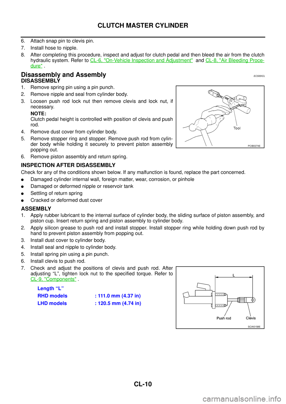
1. Remove spring pin using a pin punch.
2. Remove nipple and seal from cylinder body.
3. Loosen push rod lock nut then remove clevis and lock nut, if
necessary.
NOTE:
Clutch pedal height is controlled with position of clevis and push
rod.
4. Remove dust cover from cylinder body.
5. Remove stopper ring and stopper. Remove push rod from cylin-
der body while holding it securely to prevent piston assembly
popping out.
6. Remove piston assembly and return spring.
INSPECTION AFTER DISASSEMBLY
Check for any of the conditions shown below. If any malfunction is found, replace the part concerned.
lDamaged cylinder internal wall, foreign matter, wear, corrosion, or pinhole
lDamaged or deformed nipple or reservoir tank
lSettling of return spring
lCracked or deformed dust cover
ASSEMBLY
1. Apply rubber lubricant to the internal surface of cylinder body, the sliding surface of piston assembly, and
piston cup. Insert return spring and piston assembly to cylinder body.
2. Apply silicon grease to push rod and install stopper. Install stopper ring while holding down push rod by
hand to prevent piston assembly from popping out.
3. Install dust cover to cylinder body.
4. Install seal and nipple to cylinder body.
5. Install spring pin using a pin punch.
6. Install clevis to push rod.
7. Check and adjust the positions of clevis and push rod. After
adjusting “L”, tighten lock nut to the specified torque. Refer to
CL-9, "
Components".
PCIB0274E
Length “L”
RHD models : 111.0 mm (4.37 in)
LHD models : 120.5 mm (4.74 in)
SCIA5158E
Page 876 of 3171
CL-12
OPERATING CYLINDER
CAUTION:
Keep painted surface on the body or other parts free of clutch fluid. If it spills, wipe up immediately
and wash the affected area with water.
2. Remove clutch hose from operating cylinder assembly.
3. Remove operating cylinder assembly mounting bolts, and then remove operating cylinder assembly from
the vehicle.
INSTALLATION
Note the following, and install in the reverse order of removal.
lInstall clutch hose with care so that it will not be bent or twisted.
lTightenclutchhosetothespecifiedtorque.
CAUTION:
Do not reuse copper washer.
lAfter completing the procedure, bleed the air from the clutch hydraulic system. Refer toCL-8, "Air Bleed-
ing Procedure".
Disassembly and AssemblyECS00ICO
DISASSEMBLY
lRemove dust cover and push rod. Then remove piston, piston cup and piston spring from cylinder body.
INSPECTION AFTER DISASSEMBLY
Check for any of the conditions shown below. If any malfunction is found, replace the part concerned.
lDamage to cylinder internal surface or piston sliding surface. Foreign matter, wear, corrosion, or pinhole
lSettling of piston spring
lCracked or deformed dust cover
ASSEMBLY
1. Apply rubber lubricant to cylinder body internal surface and rubber grease to piston cup and piston. Insert
piston assembly and piston spring into cylinder body.
2. Apply rubber grease to dust cover and then install push rod and dust cover.