2005 NISSAN NAVARA torque
[x] Cancel search: torquePage 1510 of 3171
EM-128
CYLINDER BLOCK
Piston Pin Outer Diameter
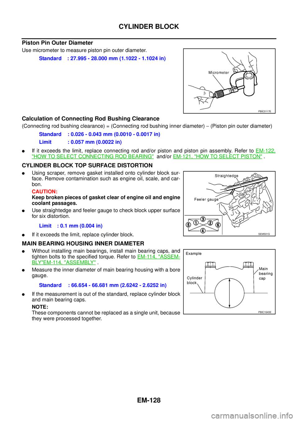
Use micrometer to measure piston pin outer diameter.
Calculation of Connecting Rod Bushing Clearance
(Connecting rod bushing clearance) = (Connecting rod bushing inner diameter)-(Piston pin outer diameter)
lIf it exceeds the limit, replace connecting rod and/or piston and piston pin assembly. Refer toEM-122,
"HOW TO SELECT CONNECTING ROD BEARING"and/orEM-121, "HOW TO SELECT PISTON".
CYLINDER BLOCK TOP SURFACE DISTORTION
lUsing scraper, remove gasket installed onto cylinder block sur-
face. Remove contamination such as engine oil, scale, and car-
bon.
CAUTION:
Keep broken pieces of gasket clear of engine oil and engine
coolant passages.
lUse straightedge and feeler gauge to check block upper surface
for six distortion.
lIf it exceeds the limit, replace cylinder block.
MAIN BEARING HOUSING INNER DIAMETER
lWithout installing main bearings, install main bearing caps, and
tighten bolts to the specified torque. Refer toEM-114, "
ASSEM-
BLY"EM-114, "ASSEMBLY".
lMeasure the inner diameter of main bearing housing with a bore
gauge.
lIf the measurement is out of the standard, replace cylinder block
andmainbearingcaps.
NOTE:
These components cannot be replaced as a single unit, because
they were processed together.Standard : 27.995 - 28.000 mm (1.1022 - 1.1024 in)
PBIC0117E
Standard : 0.026 - 0.043 mm (0.0010 - 0.0017 in)
Limit : 0.057 mm (0.0022 in)
Limit : 0.1 mm (0.004 in)
SEM501G
Standard : 66.654 - 66.681 mm (2.6242 - 2.6252 in)
PBIC1643E
Page 1512 of 3171
EM-130
CYLINDER BLOCK
2. Install main bearing caps and tighten bolts to the specified torque. Refer toEM-114, "ASSEMBLY".This
will prevent distortion of cylinder bores.
3. Cut cylinder bore.
NOTE:
lWhen any cylinder needs boring, all other cylinders must also be bored.
lDo not cut too much out of cylinder bore at a time. Cut only 0.05 mm (0.0020 in) or so at a time.
4. Hone cylinders to obtain the specified piston-to-cylinder bore clearance.
5. Measure finished cylinder bore for the out-of-round and taper.
NOTE:
lMeasurement should be done after cylinder bore cools down.
CRANKSHAFT MAIN JOURNAL DIAMETER
lUse micrometer to measure crankshaft main journal diameter.
lIf out of the standard, measure the main bearing oil clearance.
then use the undersize bearing. Refer toEM-132, "
MAIN BEAR-
ING OIL CLEARANCE".
CRANKSHAFT PIN JOURNAL DIAMETER
lUse micrometer to measure crankshaft pin journal diameter.
lIf out of the standard, measure the connecting rod bearing oil
clearance. then use the undersize bearing. Refer toEM-131,
"CONNECTING ROD BEARING OIL CLEARANCE".
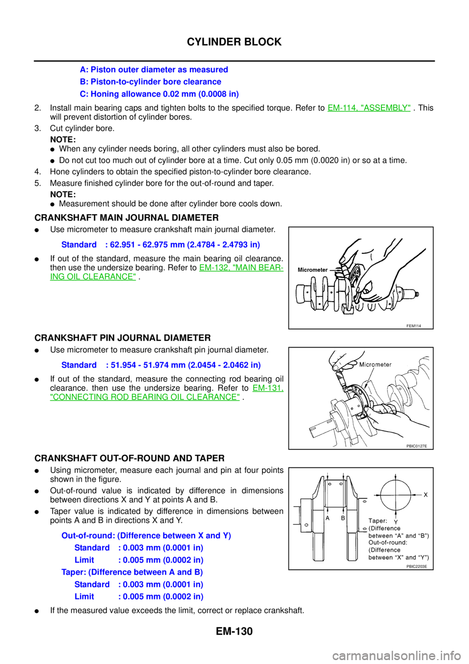
CRANKSHAFT OUT-OF-ROUND AND TAPER
lUsing micrometer, measure each journal and pin at four points
showninthefigure.
lOut-of-round value is indicated by difference in dimensions
between directions X and Y at points A and B.
lTaper value is indicated by difference in dimensions between
points A and B in directions X and Y.
lIf the measured value exceeds the limit, correct or replace crankshaft.A: Piston outer diameter as measured
B: Piston-to-cylinder bore clearance
C: Honing allowance 0.02 mm (0.0008 in)
Standard : 62.951 - 62.975 mm (2.4784 - 2.4793 in)
FEM114
Standard : 51.954 - 51.974 mm (2.0454 - 2.0462 in)
PBIC0127E
Out-of-round: (Difference between X and Y)
Standard : 0.003 mm (0.0001 in)
Limit : 0.005 mm (0.0002 in)
Taper: (Difference between A and B)
Standard : 0.003 mm (0.0001 in)
Limit : 0.005 mm (0.0002 in)
PBIC2203E
Page 1513 of 3171
CYLINDER BLOCK
EM-131
C
D
E
F
G
H
I
J
K
L
MA
EM
lIf corrected, measure the bearing oil clearance of the corrected journal and/or pin. Then select the main
bearing or connecting rod bearing. Refer toEM-132, "
MAIN BEARING OIL CLEARANCE"and/orEM-
131, "CONNECTING ROD BEARING OIL CLEARANCE".
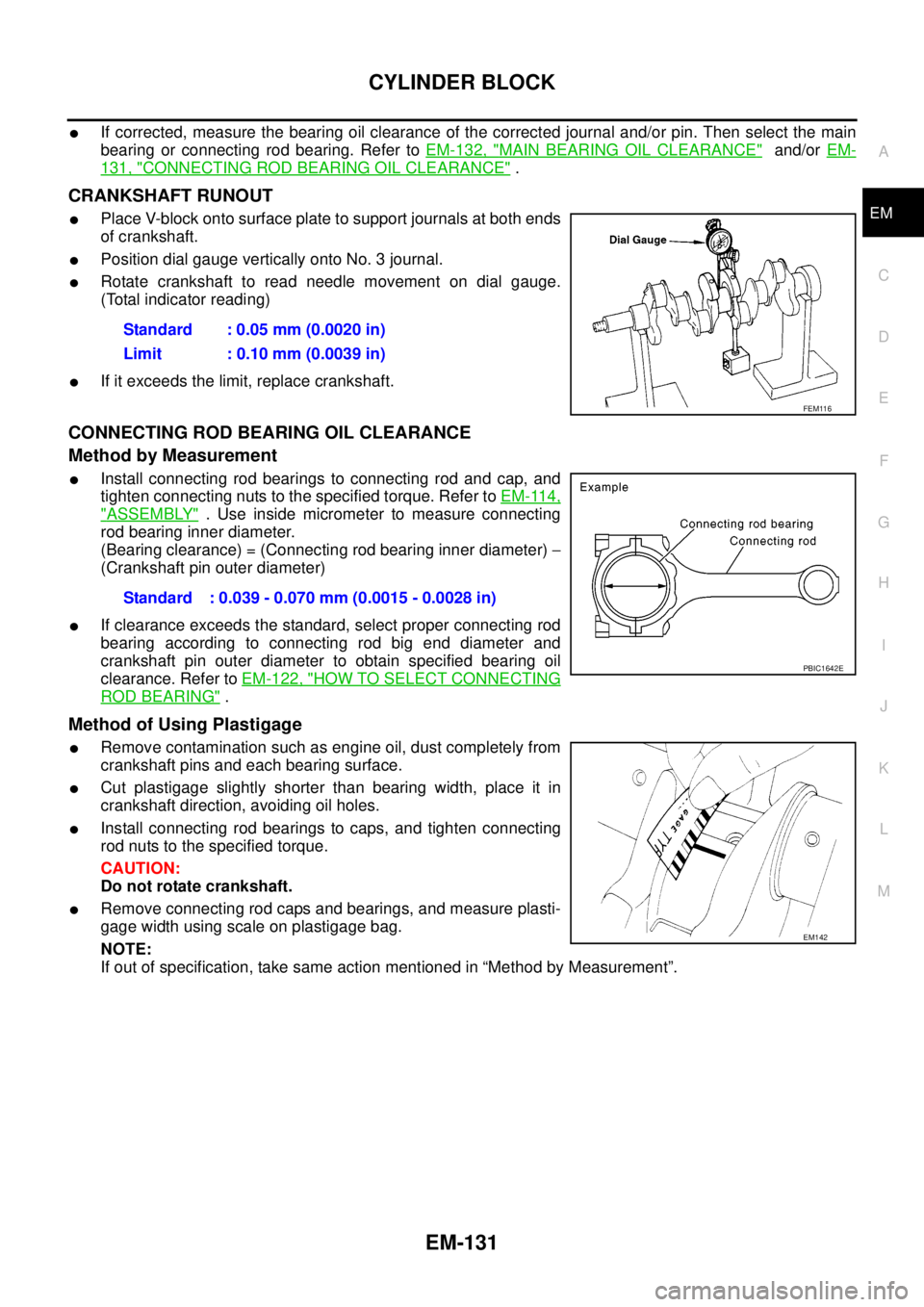
CRANKSHAFT RUNOUT
lPlace V-block onto surface plate to support journals at both ends
of crankshaft.
lPosition dial gauge vertically onto No. 3 journal.
lRotate crankshaft to read needle movement on dial gauge.
(Total indicator reading)
lIf it exceeds the limit, replace crankshaft.
CONNECTING ROD BEARING OIL CLEARANCE
Method by Measurement
lInstall connecting rod bearings to connecting rod and cap, and
tighten connecting nuts to the specified torque. Refer toEM-114,
"ASSEMBLY". Use inside micrometer to measure connecting
rod bearing inner diameter.
(Bearing clearance) = (Connecting rod bearing inner diameter)-
(Crankshaft pin outer diameter)
lIf clearance exceeds the standard, select proper connecting rod
bearing according to connecting rod big end diameter and
crankshaft pin outer diameter to obtain specified bearing oil
clearance. Refer toEM-122, "
HOW TO SELECT CONNECTING
ROD BEARING".
Method of Using Plastigage
lRemove contamination such as engine oil, dust completely from
crankshaft pins and each bearing surface.
lCut plastigage slightly shorter than bearing width, place it in
crankshaft direction, avoiding oil holes.
lInstall connecting rod bearings to caps, and tighten connecting
rod nuts to the specified torque.
CAUTION:
Do not rotate crankshaft.
lRemove connecting rod caps and bearings, and measure plasti-
gage width using scale on plastigage bag.
NOTE:
If out of specification, take same action mentioned in “Method by Measurement”.Standard : 0.05 mm (0.0020 in)
Limit : 0.10 mm (0.0039 in)
FEM116
Standard : 0.039 - 0.070 mm (0.0015 - 0.0028 in)
PBIC1642E
EM142
Page 1514 of 3171
EM-132
CYLINDER BLOCK
MAIN BEARING OIL CLEARANCE
Method by Measurement
lInstall main bearings to cylinder block and bearing cap, and
tighten the bolts to the specified torque. Refer toEM-114,
"ASSEMBLY". Then, measure the inner diameter of main bear-
ings.
(Bearing clearance) = (Bearing inner diameter)-(Crankshaft
journal outer diameter)
lIf out of the standard, check main bearing housing inner diame-
ter and crankshaft journal outer diameter, and select appropriate
main bearing to adjust clearance to specifications. Refer toEM-
123, "HOW TO SELECT MAIN BEARING".
Method of Using Plastigage
lRemove contamination such as engine oil and dust completely
from crankshaft journals and each bearing surface.
lCut plastigage slightly shorter than bearing width. Place it in
crankshaft turning direction, avoiding oil holes.
lInstall main bearings and bearing cap and tighten to the speci-
fied torque. Refer toEM-114, "
ASSEMBLY"for the tightening
procedure.
CAUTION:
Do not rotate crankshaft.
lRemove main bearings and bearing caps, and measure plasti-
gage width using scale on plastigage bag.
NOTE:
If out of specification, take same action mentioned in “Method by Measurement”.
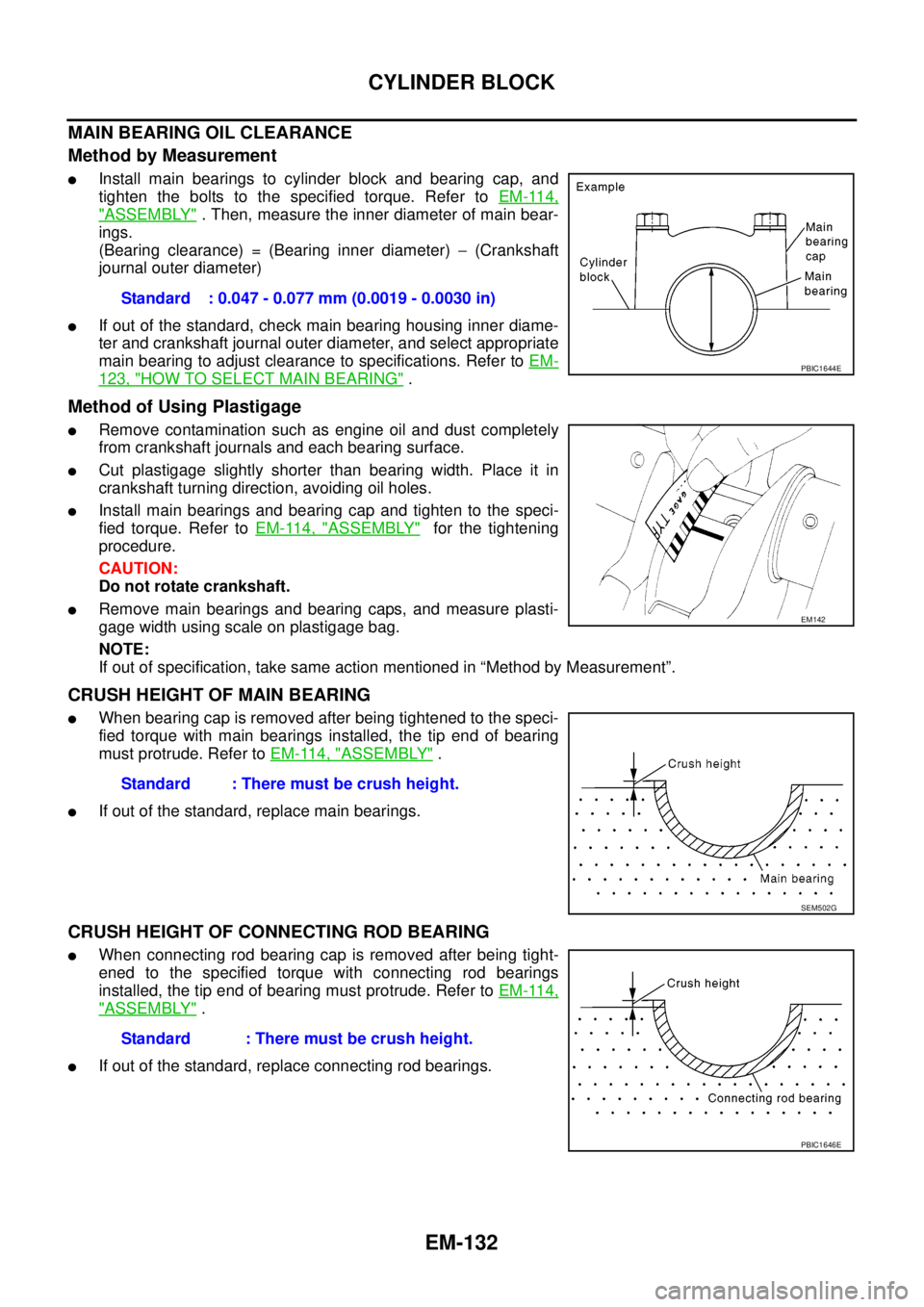
CRUSH HEIGHT OF MAIN BEARING
lWhen bearing cap is removed after being tightened to the speci-
fied torque with main bearings installed, the tip end of bearing
must protrude. Refer toEM-114, "
ASSEMBLY".
lIf out of the standard, replace main bearings.
CRUSH HEIGHT OF CONNECTING ROD BEARING
lWhen connecting rod bearing cap is removed after being tight-
ened to the specified torque with connecting rod bearings
installed, the tip end of bearing must protrude. Refer toEM-114,
"ASSEMBLY".
lIf out of the standard, replace connecting rod bearings.Standard : 0.047 - 0.077 mm (0.0019 - 0.0030 in)
PBIC1644E
EM142
Standard : There must be crush height.
SEM502G
Standard : There must be crush height.
PBIC1646E
Page 1516 of 3171
EM-134
CYLINDER BLOCK
FLYWHEEL DEFLECTION
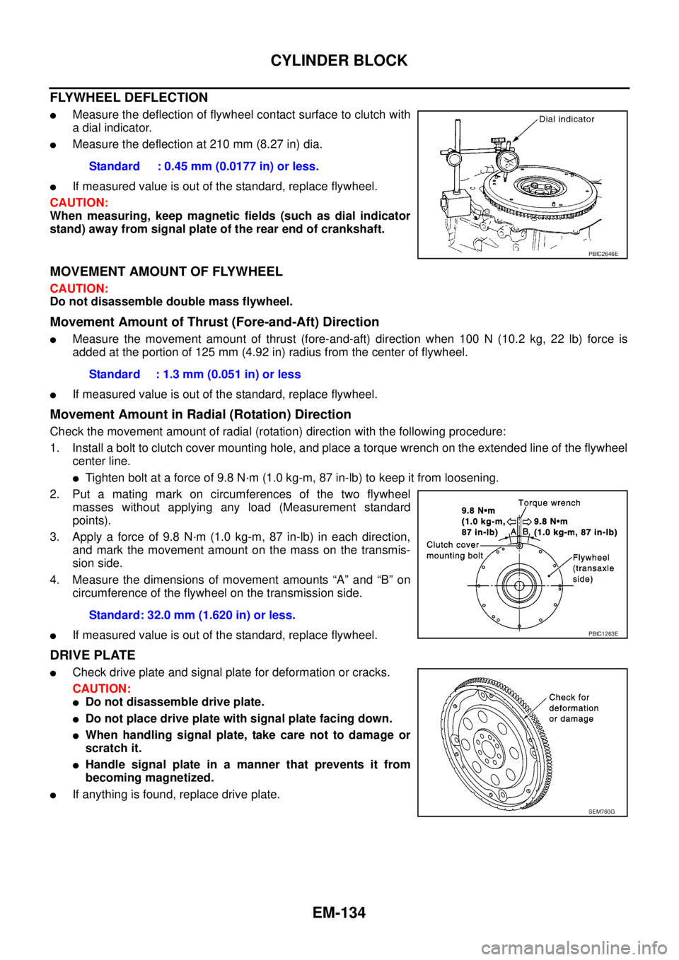
lMeasure the deflection of flywheel contact surface to clutch with
a dial indicator.
lMeasure the deflection at 210 mm (8.27 in) dia.
lIf measured value is out of the standard, replace flywheel.
CAUTION:
When measuring, keep magnetic fields (such as dial indicator
stand) away from signal plate of the rear end of crankshaft.
MOVEMENT AMOUNT OF FLYWHEEL
CAUTION:
Do not disassemble double mass flywheel.
Movement Amount of Thrust (Fore-and-Aft) Direction
lMeasure the movement amount of thrust (fore-and-aft) direction when 100 N (10.2 kg, 22 lb) force is
added at the portion of 125 mm (4.92 in) radius from the center of flywheel.
lIf measured value is out of the standard, replace flywheel.
Movement Amount in Radial (Rotation) Direction
Check the movement amount of radial (rotation) direction with the following procedure:
1. Install a bolt to clutch cover mounting hole, and place a torque wrench on the extended line of the flywheel
center line.
lTighten bolt at a force of 9.8 N·m (1.0 kg-m, 87 in-lb) to keep it from loosening.
2. Put a mating mark on circumferences of the two flywheel
masses without applying any load (Measurement standard
points).
3. Apply a force of 9.8 N·m (1.0 kg-m, 87 in-lb) in each direction,
and mark the movement amount on the mass on the transmis-
sion side.
4. Measure the dimensions of movement amounts “A” and “B” on
circumference of the flywheel on the transmission side.
lIf measured value is out of the standard, replace flywheel.
DRIVE PLATE
lCheck drive plate and signal plate for deformation or cracks.
CAUTION:
lDo not disassemble drive plate.
lDo not place drive plate with signal plate facing down.
lWhen handling signal plate, take care not to damage or
scratch it.
lHandle signal plate in a manner that prevents it from
becoming magnetized.
lIf anything is found, replace drive plate.Standard : 0.45 mm (0.0177 in) or less.
PBIC2646E
Standard : 1.3 mm (0.051 in) or less
Standard: 32.0 mm (1.620 in) or less.
PBIC1263E
SEM760G
Page 1531 of 3171
EXHAUST SYSTEM
EX-3
C
D
E
F
G
H
I
J
K
L
MA
EX
Removal and InstallationEBS01E7B
CAUTION:
lBe sure to use genuine exhaust system parts or equivalents which are specially designed for heat
resistance, corrosion resistance and shape.
lPerform the operation with the exhaust system fully cooled down because the system will be hot
just after engine stops.
lBe careful not to cut your hand on the insulator edge.
REMOVAL
Separate each connection as necessary.
CAUTION:
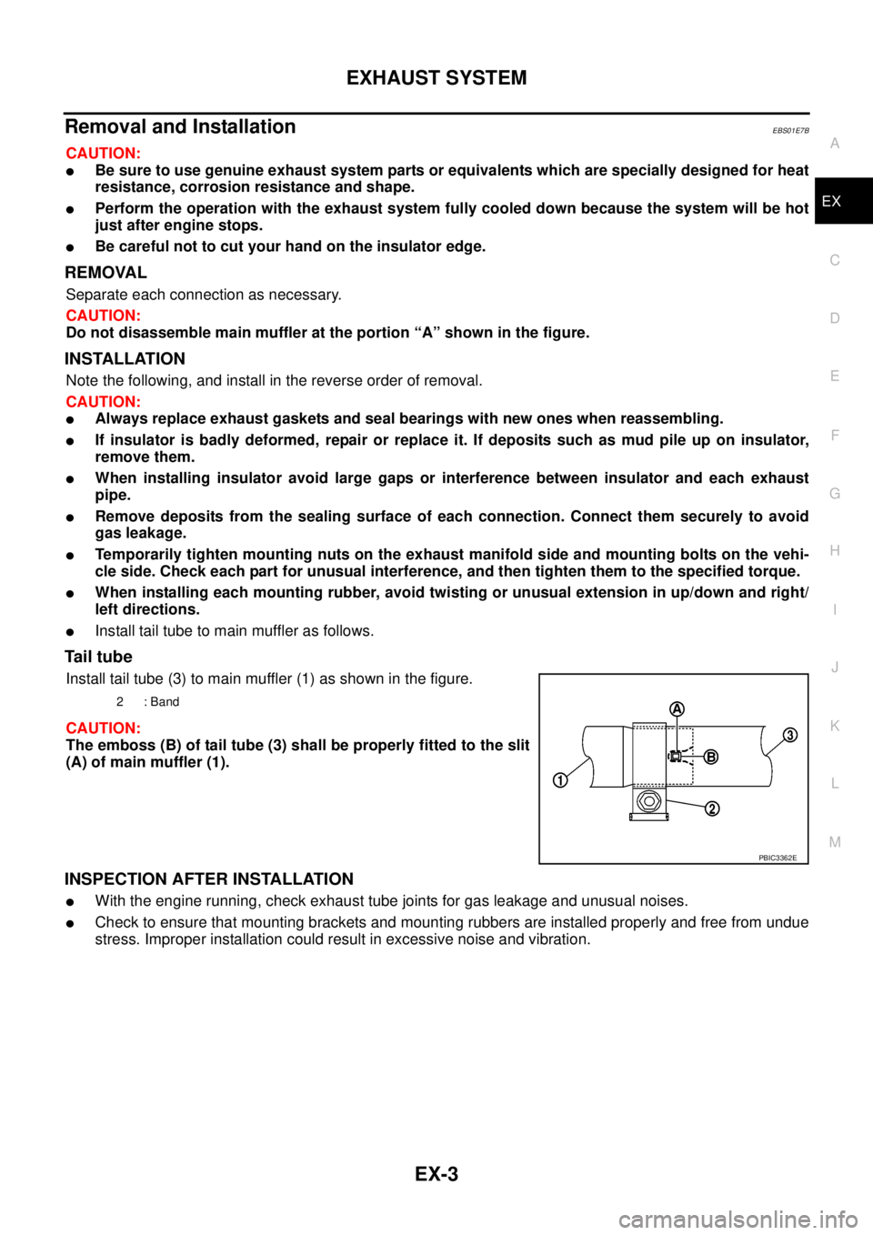
Do not disassemble main muffler at the portion “A” shown in the figure.
INSTALLATION
Note the following, and install in the reverse order of removal.
CAUTION:
lAlways replace exhaust gaskets and seal bearings with new ones when reassembling.
lIf insulator is badly deformed, repair or replace it. If deposits such as mud pile up on insulator,
remove them.
lWhen installing insulator avoid large gaps or interference between insulator and each exhaust
pipe.
lRemove deposits from the sealing surface of each connection. Connect them securely to avoid
gas leakage.
lTemporarily tighten mounting nuts on the exhaust manifold side and mounting bolts on the vehi-
cle side. Check each part for unusual interference, and then tighten them to the specified torque.
lWhen installing each mounting rubber, avoid twisting or unusual extension in up/down and right/
left directions.
lInstall tail tube to main muffler as follows.
Ta i l t u b e
Install tail tube (3) to main muffler (1) as shown in the figure.
CAUTION:
The emboss (B) of tail tube (3) shall be properly fitted to the slit
(A) of main muffler (1).
INSPECTION AFTER INSTALLATION
lWith the engine running, check exhaust tube joints for gas leakage and unusual noises.
lCheck to ensure that mounting brackets and mounting rubbers are installed properly and free from undue
stress. Improper installation could result in excessive noise and vibration.
2:Band
PBIC3362E
Page 1537 of 3171
WHEEL HUB
FAX-5
C
E
F
G
H
I
J
K
L
MA
B
FA X
WHEEL HUBPFP:43202
On-Vehicle Inspection and ServiceEDS003I7
Make sure the mounting conditions (looseness, backlash) of each component and component status (wear,
damage) are normal.
WHEEL BEARING INSPECTION
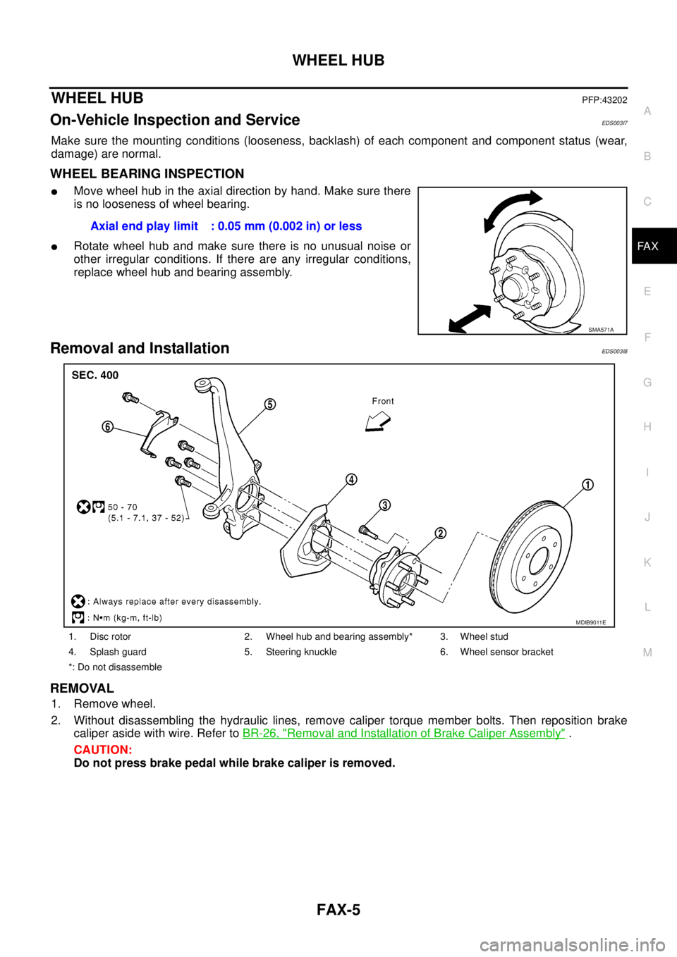
lMove wheel hub in the axial direction by hand. Make sure there
is no looseness of wheel bearing.
lRotate wheel hub and make sure there is no unusual noise or
other irregular conditions. If there are any irregular conditions,
replace wheel hub and bearing assembly.
Removal and InstallationEDS003I8
REMOVAL
1. Remove wheel.
2. Without disassembling the hydraulic lines, remove caliper torque member bolts. Then reposition brake
caliper aside with wire. Refer toBR-26, "
Removal and Installation of Brake Caliper Assembly".
CAUTION:
Do not press brake pedal while brake caliper is removed.Axial end play limit : 0.05 mm (0.002 in) or less
SMA571A
1. Disc rotor 2. Wheel hub and bearing assembly* 3. Wheel stud
4. Splash guard 5. Steering knuckle 6. Wheel sensor bracket
*: Do not disassemble
MDIB9011E
Page 1547 of 3171
FFD-1
FRONT FINAL DRIVE
D DRIVELINE/AXLE
CONTENTS
C
E
F
G
H
I
J
K
L
M
SECTIONFFD
A
B
FFD
FRONT FINAL DRIVE
PRECAUTIONS .......................................................... 2
Service Notice or Precautions .................................. 2
PREPARATION ........................................................... 3
Special Service Tools ............................................... 3
Commercial Service Tools ........................................ 5
NOISE, VIBRATION AND HARSHNESS (NVH)
TROUBLESHOOTING ................................................ 6
NVH Troubleshooting Chart ..................................... 6
DESCRIPTION ............................................................ 7
Cross-Sectional View ............................................... 7
DIFFERENTIAL GEAR OIL ........................................ 8
Changing Differential Gear Oil ................................. 8
DRAINING ............................................................. 8
FILLING ................................................................. 8
Checking Differential Gear Oil .................................. 8
OIL LEAKAGE AND OIL LEVEL ........................... 8
FRONT OIL SEAL ...................................................... 9
Removal and Installation .......................................... 9
IDENTIFICATION STAMP OF REPLACEMENT
FREQUENCY OF FRONT OIL SEAL ................... 9
REMOVAL ............................................................. 9
INSTALLATION .................................................... 11
SIDE OIL SEAL ........................................................ 13
Removal and Installation ........................................ 13
REMOVAL ........................................................... 13
INSTALLATION ................................................... 13REAR COVER GASKET ........................................... 14
Removal and Installation ........................................ 14
REMOVAL ........................................................... 14
INSTALLATION ................................................... 14
FRONT FINAL DRIVE ASSEMBLY .......................... 15
Removal and Installation ........................................ 15
REMOVAL ........................................................... 15
INSTALLATION ................................................... 16
Disassembly and Assembly .................................... 17
COMPONENTS ................................................... 17
ASSEMBLY INSPECTION AND ADJUSTMENT... 18
DISASSEMBLY ................................................... 21
INSPECTION AFTER DISASSEMBLY ................ 26
ADJUSTMENT AND SELECTION ADJUSTING
WASHERS .......................................................... 27
ASSEMBLY ......................................................... 28
SERVICE DATA AND SPECIFICATIONS (SDS) ...... 37
General Specifications ............................................ 37
Inspection and Adjustment ..................................... 37
DRIVE GEAR RUNOUT ...................................... 37
DIFFERENTIAL SIDE GEAR CLEARANCE ....... 37
PRELOAD TORQUE ........................................... 37
BACKLASH ......................................................... 37
COMPANION FLANGE RUNOUT ....................... 37
SELECTIVE PARTS ............................................ 37