Page 1548 of 3171

FFD-2
PRECAUTIONS
PRECAUTIONS
PFP:00001
ServiceNoticeorPrecautionsEDS0034W
lBefore starting diagnosis of the vehicle, understand the symptoms well. Perform correct and systematic
operations.
lCheck for the correct installation status prior to removal or disassembly. When matching marks are
required, be certain they do not interfere with the function of the parts they are applied to.
lOverhaul should be done in a clean work area, a dust proof area is recommended.
lBefore disassembly, completely remove sand and mud from the exterior of the unit, preventing them from
entering into the unit during disassembly or assembly.
lAlways use shop paper for cleaning the inside of components.
lAvoid using cotton gloves or a shop cloth to prevent the entering of lint.
lCheck appearance of the disassembled parts for damage, deformation, and unusual wear. Replace them
with new ones if necessary.
lGaskets, seals and O-rings should be replaced any time the unit is disassembled.
lClean and flush the parts sufficiently and blow them dry.
lBe careful not to damage sliding surfaces and mating surfaces.
lWhen applying sealant, remove the old sealant from the mating surface; then remove any moisture, oil,
and foreign materials from the application and mating surfaces.
lIn principle, tighten bolts or nuts gradually in several steps working diagonally from inside to outside. If a
tightening sequence is specified, observe it.
lDuring assembly, observe the specified tightening torque.
lAdd new differential gear oil, petroleum jelly, or multi-purpose grease, as specified.
Page 1549 of 3171
PREPARATION
FFD-3
C
E
F
G
H
I
J
K
L
MA
B
FFD
PREPARATIONPFP:00002
Special Service ToolsEDS0034X
Tool number
Tool nameDescription
KV381054S0
PullerRemoving front oil seal
ST30720000
Drift
a: 77 mm (3.03 in) dia.
b: 55.5 mm (2.185 in) dia.
lInstalling front oil seal
lInstalling side oil seal
ST27863000
Drift
a: 74.5 mm (2.933 in) dia.
b: 62.5 mm (2.461 in) dia.
lInstalling front oil seal
lInstalling side oil seal
ST29020001
PullerSeparating the upper link ball joint stud
ST3127S000
Preload gauge
1: GG91030000
Torque wrench
2: HT62940000
Socket adapter (1/2²)
3: HT62900000
Socket adapter (3/8²)Measuring pinion bearing preload and total
preload
K V 1 0 1111 0 0
Seal cutterRemoving rear cover
ST3306S001
Differential side bearing puller set
1: ST33051001
Puller
2: ST33061000
Base
a: 28.5 mm (1.122 in) dia.
b: 38 mm (1.50 in) dia.Removing and installing side bearing inner
race
ZZA0601D
ZZA0811D
ZZA1003D
NT143
NT124
S-NT046
NT072
Page 1554 of 3171

FFD-8
DIFFERENTIAL GEAR OIL
DIFFERENTIAL GEAR OIL
PFP:KLD30
Changing Differential Gear OilEDS00351
DRAINING
1. Stop the engine.
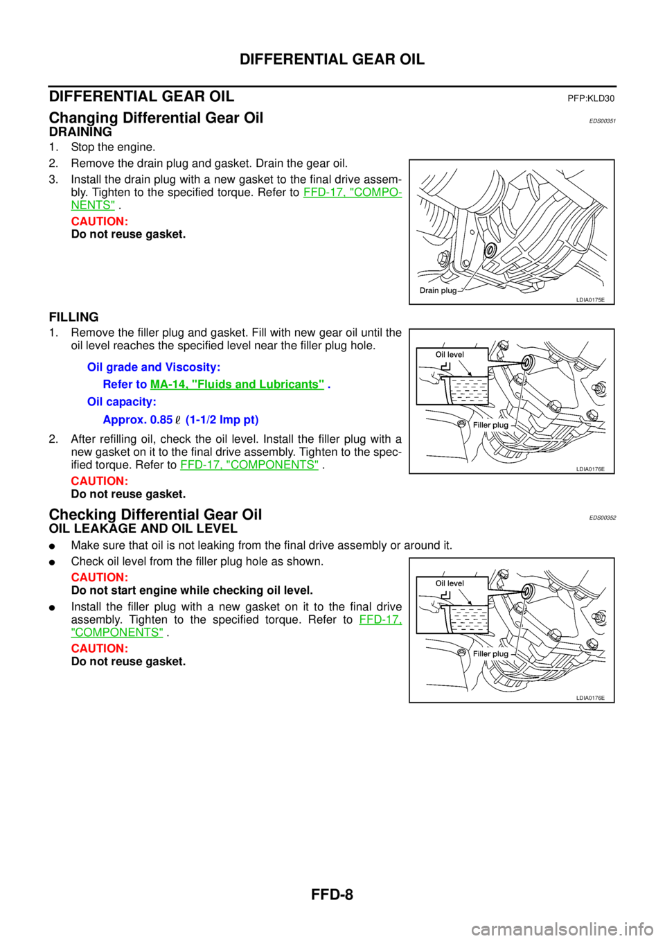
2. Remove the drain plug and gasket. Drain the gear oil.
3. Install the drain plug with a new gasket to the final drive assem-
bly. Tighten to the specified torque. Refer toFFD-17, "
COMPO-
NENTS".
CAUTION:
Do not reuse gasket.
FILLING
1. Remove the filler plug and gasket. Fill with new gear oil until the
oil level reaches the specified level near the filler plug hole.
2. After refilling oil, check the oil level. Install the filler plug with a
new gasket on it to the final drive assembly. Tighten to the spec-
ified torque. Refer toFFD-17, "
COMPONENTS".
CAUTION:
Do not reuse gasket.
Checking Differential Gear OilEDS00352
OIL LEAKAGE AND OIL LEVEL
lMake sure that oil is not leaking from the final drive assembly or around it.
lCheck oil level from the filler plug hole as shown.
CAUTION:
Do not start engine while checking oil level.
lInstall the filler plug with a new gasket on it to the final drive
assembly. Tighten to the specified torque. Refer toFFD-17,
"COMPONENTS".
CAUTION:
Do not reuse gasket.
LDIA0175E
Oil grade and Viscosity:
Refer toMA-14, "
Fluids and Lubricants".
Oil capacity:
Approx. 0.85 (1-1/2 Imp pt)
LDIA0176E
LDIA0176E
Page 1555 of 3171

FRONT OIL SEAL
FFD-9
C
E
F
G
H
I
J
K
L
MA
B
FFD
FRONT OIL SEALPFP:38189
Removal and InstallationEDS00353
CAUTION:
Verify identification stamp of replacement frequency put in the lower part of gear carrier to determine
replacement for collapsible spacer when replacing front oil seal. Refer toFFD-9, "
IDENTIFICATION
STAMP OF REPLACEMENT FREQUENCY OF FRONT OIL SEAL". If necessary collapsible spacer
replacement, remove final drive assembly and disassemble it to replace front oil seal and collapsible
spacer. Refer toFFD-15, "
Removal and Installation"andFFD-17, "Disassembly and Assembly".
NOTE:
The reuse of collapsible spacer is prohibited in principle. However, it is reusable on a one-time basis
only in cases when replacing front oil seal.
IDENTIFICATION STAMP OF REPLACEMENT FREQUENCY OF FRONT OIL SEAL
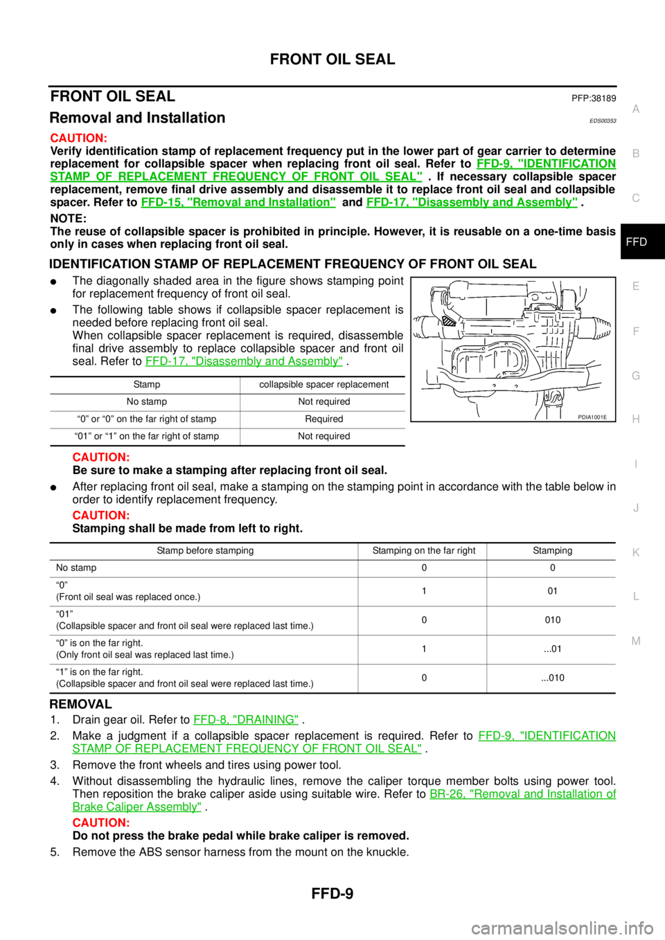
lThe diagonally shaded area in the figure shows stamping point
for replacement frequency of front oil seal.
lThe following table shows if collapsible spacer replacement is
needed before replacing front oil seal.
When collapsible spacer replacement is required, disassemble
final drive assembly to replace collapsible spacer and front oil
seal. Refer toFFD-17, "
Disassembly and Assembly".
CAUTION:
Be sure to make a stamping after replacing front oil seal.
lAfter replacing front oil seal, make a stamping on the stamping point in accordance with the table below in
order to identify replacement frequency.
CAUTION:
Stamping shall be made from left to right.
REMOVAL
1. Drain gear oil. Refer toFFD-8, "DRAINING".
2. Make a judgment if a collapsible spacer replacement is required. Refer toFFD-9, "
IDENTIFICATION
STAMP OF REPLACEMENT FREQUENCY OF FRONT OIL SEAL".
3. Remove the front wheels and tires using power tool.
4. Without disassembling the hydraulic lines, remove the caliper torque member bolts using power tool.
Then reposition the brake caliper aside using suitable wire. Refer toBR-26, "
Removal and Installation of
Brake Caliper Assembly".
CAUTION:
Do not press the brake pedal while brake caliper is removed.
5. Remove the ABS sensor harness from the mount on the knuckle.
Stamp collapsible spacer replacement
No stamp Not required
“0” or “0” on the far right of stamp Required
“01” or “1” on the far right of stamp Not required
PDIA1001E
Stamp before stamping Stamping on the far right Stamping
No stamp00
“0”
(Front oil seal was replaced once.)101
“01”
(Collapsible spacer and front oil seal were replaced last time.)0010
“0”isonthefarright.
(Only front oil seal was replaced last time.)1 ...01
“1”isonthefarright.
(Collapsible spacer and front oil seal were replaced last time.)0 ...010
Page 1558 of 3171

FFD-12
FRONT OIL SEAL
3. Apply anti-corrosion oil to the thread and seat of new drive pin-
ion lock nut, and temporarily tighten drive pinion lock nut to drive
pinion.
CAUTION:
Do not reuse drive pinion lock nut.
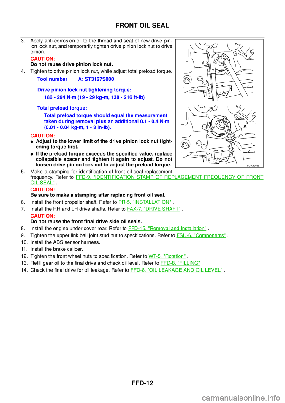
4. Tighten to drive pinion lock nut, while adjust total preload torque.
CAUTION:
lAdjust to the lower limit of the drive pinion lock nut tight-
ening torque first.
lIf the preload torque exceeds the specified value, replace
collapsible spacer and tighten it again to adjust. Do not
loosen drive pinion lock nut to adjust the preload torque.
5. Make a stamping for identification of front oil seal replacement
frequency. Refer toFFD-9, "
IDENTIFICATION STAMP OF REPLACEMENT FREQUENCY OF FRONT
OIL SEAL".
CAUTION:
Be sure to make a stamping after replacing front oil seal.
6. Install the front propeller shaft. Refer toPR-5, "
INSTALLATION".
7. Install the RH and LH drive shafts. Refer toFA X - 7 , "
DRIVE SHAFT".
CAUTION:
Do not reuse the front final drive side oil seals.
8. Install the engine under cover rear. Refer toFFD-15, "
Removal and Installation".
9. Tighten the upper link ball joint stud nut to specifications. Refer toFSU-6, "
Components".
10. Install the ABS sensor harness.
11. Install the brake caliper.
12. Tighten the front wheel nuts to specification. Refer toWT-5, "
Rotation".
13. Refill gear oil to the final drive and check oil level. Refer toFFD-8, "
FILLING".
14. Check the final drive for oil leakage. Refer toFFD-8, "
OIL LEAKAGE AND OIL LEVEL". Tool number A: ST3127S000
Drive pinion lock nut tightening torque:
186 - 294 N·m (19 - 29 kg-m, 138 - 216 ft-lb)
Total preload torque:
Total preload torque should equal the measurement
taken during removal plus an additional 0.1 - 0.4 N·m
(0.01 - 0.04 kg-m, 1 - 3 in-lb).
PDIA1003E
Page 1559 of 3171

SIDE OIL SEAL
FFD-13
C
E
F
G
H
I
J
K
L
MA
B
FFD
SIDE OIL SEALPFP:33142
Removal and InstallationEDS00354
REMOVAL
1. Remove the front wheels and tires using power tool.
2. Without disassembling the hydraulic lines, remove the caliper torque member bolts using power tool.
Then reposition the brake caliper aside using suitable wire. Refer toBR-26, "
Removal and Installation of
Brake Caliper Assembly".
CAUTION:
Do not press the brake pedal while brake caliper is removed.
3. Remove the ABS sensor harness from the mount on the knuckle.
CAUTION:
Do not pull on the ABS sensor harness.
4. Support the lower link using a suitable jack.
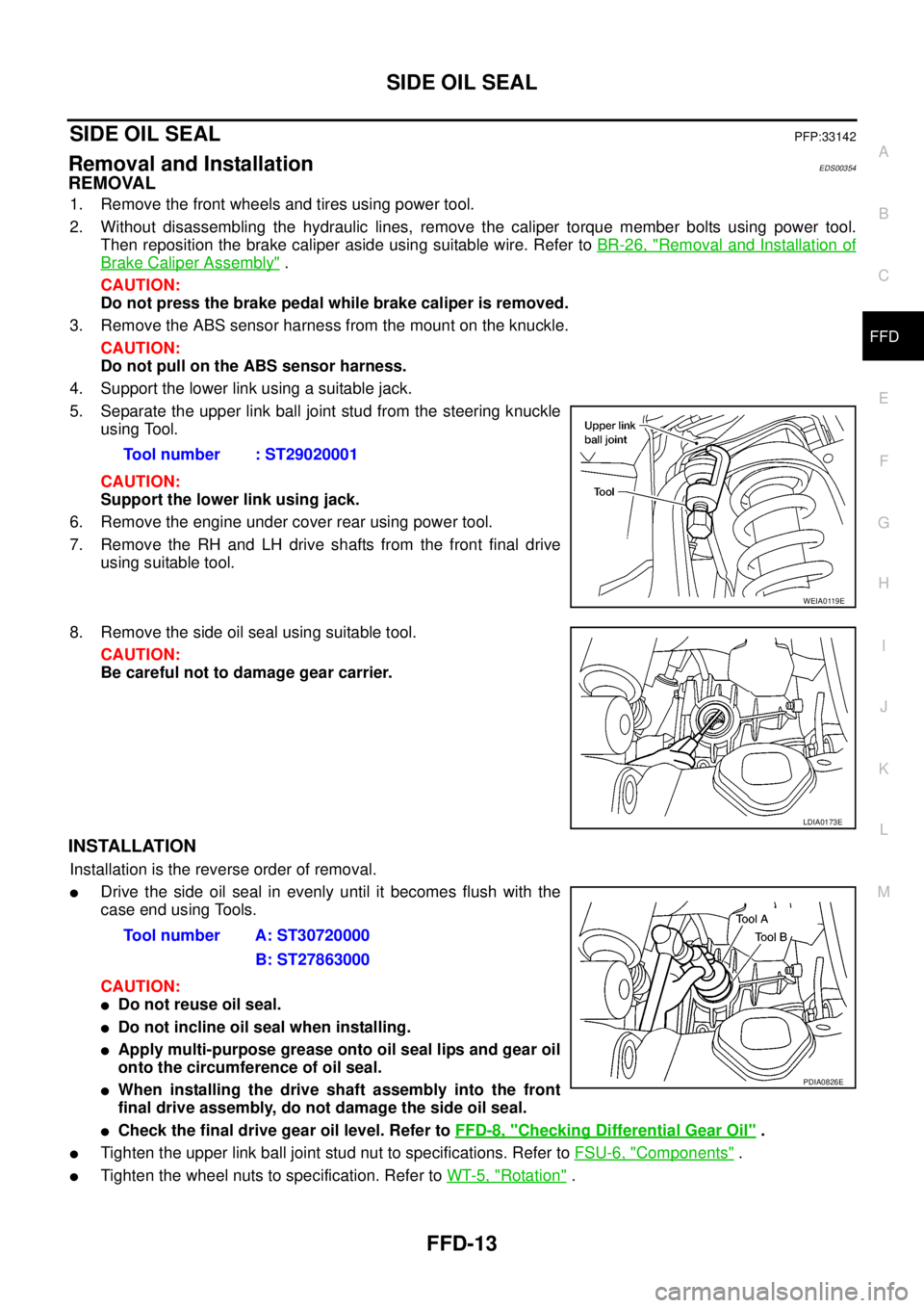
5. Separate the upper link ball joint stud from the steering knuckle
using Tool.
CAUTION:
Support the lower link using jack.
6. Remove the engine under cover rear using power tool.
7. Remove the RH and LH drive shafts from the front final drive
using suitable tool.
8. Remove the side oil seal using suitable tool.
CAUTION:
Be careful not to damage gear carrier.
INSTALLATION
Installation is the reverse order of removal.
lDrive the side oil seal in evenly until it becomes flush with the
case end using Tools.
CAUTION:
lDo not reuse oil seal.
lDo not incline oil seal when installing.
lApply multi-purpose grease onto oil seal lips and gear oil
onto the circumference of oil seal.
lWhen installing the drive shaft assembly into the front
final drive assembly, do not damage the side oil seal.
lCheck the final drive gear oil level. Refer toFFD-8, "Checking Differential Gear Oil".
lTighten the upper link ball joint stud nut to specifications. Refer toFSU-6, "Components".
lTighten the wheel nuts to specification. Refer toWT-5, "Rotation". Tool number : ST29020001
WEIA0119E
LDIA0173E
Tool number A: ST30720000
B: ST27863000
PDIA0826E
Page 1560 of 3171
FFD-14
REAR COVER GASKET
REAR COVER GASKET
PFP:38320
Removal and InstallationEDS00355
REMOVAL
1. Remove front final drive. Refer toFFD-15, "Removal and Installation".
2. Remove the rear cover bolts, then remove the rear cover from the gear carrier.
INSTALLATION
1. Apply a 3 mm (0.12 in) bead of sealant to the mating surface of
the rear cover.
CAUTION:
Remove any old sealant adhering to the mating surfaces.
Also remove any moisture, oil, or foreign material adhering
to the application and mating surfaces.
2. Install the rear cover to the gear carrier. Tighten the bolts to the
specified torque. Refer toFFD-17, "
COMPONENTS".
3. Install the front final drive assembly. Refer toFFD-15, "
Removal
and Installation".
4. Fill the final drive with recommended gear oil. Refer toFFD-8,
"Checking Differential Gear Oil".
PDIA0952E
Page 1561 of 3171
FRONT FINAL DRIVE ASSEMBLY
FFD-15
C
E
F
G
H
I
J
K
L
MA
B
FFD
FRONT FINAL DRIVE ASSEMBLYPFP:38500
Removal and InstallationEDS00356
REMOVAL
1. Remove the front wheels and tires using power tool.
2. Without disassembling the hydraulic lines, remove the caliper torque member bolts using power tool.
Then reposition the brake caliper aside using suitable wire. Refer toBR-26, "
Removal and Installation of
Brake Caliper Assembly".
CAUTION:
Do not press the brake pedal while brake caliper is removed.
3. Remove the ABS sensor harness from the mount on the knuckle.
1. Breather hose 2. Front final drive assembly 3. Front crossmember
4. Engine under cover rear
PDIA1035E