2005 NISSAN NAVARA torque
[x] Cancel search: torquePage 2305 of 3171
MA-30
CHASSIS AND BODY MAINTENANCE
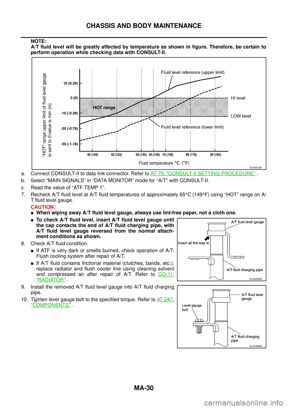
NOTE:
A/T fluid level will be greatly affected by temperature as shown in figure. Therefore, be certain to
perform operation while checking data with CONSULT-II.
a. Connect CONSULT-II to data link connector. Refer toAT-79, "
CONSULT-II SETTING PROCEDURE".
b. Select “MAIN SIGNALS” in “DATA MONITOR” mode for “A/T” with CONSULT-II.
c. Readthevalueof“ATFTEMP1”.
7. Recheck A/T fluid level at A/T fluid temperatures of approximately 65°C(149°F)using“HOT”rangeonA/
T fluid level gauge.
CAUTION:
lWhen wiping away A/T fluid level gauge, always use lint-free paper, not a cloth one.
lTo check A/T fluid level, insert A/T fluid level gauge until
the cap contacts the end of A/T fluid charging pipe, with
A/T fluid level gauge reversed from the normal attach-
ment conditions as shown.
8. Check A/T fluid condition.
lIf ATF is very dark or smells burned, check operation of A/T.
Flush cooling system after repair of A/T.
lIf A/T fluid contains frictional material (clutches, bands, etc.),
replace radiator and flush cooler line using cleaning solvent
and compressed air after repair of A/T. Refer toCO-11,
"RADIATOR".
9. Install the removed A/T fluid level gauge into A/T fluid charging
pipe.
10. Tighten level gauge bolt to the specified torque. Refer toAT-247,
"COMPONENTS".
SLIA0016E
SCIA2899E
SCIA4896E
Page 2306 of 3171
CHASSIS AND BODY MAINTENANCE
MA-31
C
D
E
F
G
H
I
J
K
MA
B
MA
Changing A/T FluidELS001K0
1. Warm up ATF.
2. Stop engine.
3. Loosen level gauge bolt.
4. Remove A/T fluid level gauge.
5. Remove drain plug and drain ATF from drain hole.
6. Install drain plug gasket and drain plug to oil pan.
CAUTION:
Do not reuse drain plug gasket.
7. Tighten drain plug to the specified torque. Refer toAT-218,
"COMPONENTS".
8. Refill with new ATF. Always refill same volume with drained ATF.
lTo replace the ATF, pour in new ATF at A/T fluid charging pipe
with the engine idling and at the same time drain the old ATF
from A/T fluid cooler hose return side.
lWhen the color of the ATF coming out is about the same as the color of the new ATF, the replacement
is complete. The amount of new ATF to use should be 30 to 50% increase of the specified amount.
CAUTION:
lUse only Genuine NISSAN ATF Matic Fluid J. Do not mix with other ATF.
lUsing ATF other than Genuine NISSAN ATF Matic Fluid J will cause deterioration in driveability
and A/T durability, and may damage the A/T, which is not covered by the NISSAN new vehicle
warranty.
lWhen filling ATF, take care not to spillover heat generating parts such as exhaust.
9. Run engine at idle speed for 5 minutes.
10. Check A/T fluid level and condition. Refer toMA-29, "
Checking A/T Fluid". If ATF is still dirty, repeat step
2 through 9.
11. Install the removed A/T fluid level gauge into A/T fluid charging pipe.
12. Tighten level gauge bolt to the specified torque. Refer toAT- 2 4 7 , "
COMPONENTS".
Checking Transfer FluidELS001IQ
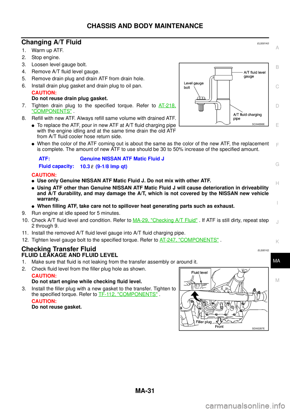
FLUID LEAKAGE AND FLUID LEVEL
1. Make sure that fluid is not leaking from the transfer assembly or around it.
2. Check fluid level from the filler plug hole as shown.
CAUTION:
Do not start engine while checking fluid level.
3. Install the filler plug with a new gasket to the transfer. Tighten to
the specified torque. Refer toTF-112, "
COMPONENTS".
CAUTION:
Do not reuse gasket.ATF: Genuine NISSAN ATF Matic Fluid J
Fluid capacity:
10.3 (9-1/8 lmp qt)
SCIA4896E
SDIA3287E
Page 2307 of 3171
MA-32
CHASSIS AND BODY MAINTENANCE
Changing Transfer Fluid
ELS001IR
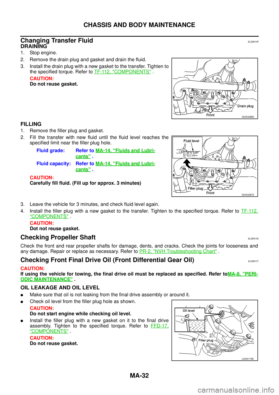
DRAINING
1. Stop engine.
2. Remove the drain plug and gasket and drain the fluid.
3. Install the drain plug with a new gasket to the transfer. Tighten to
the specified torque. Refer toTF-112, "
COMPONENTS".
CAUTION:
Do not reuse gasket.
FILLING
1. Remove the filler plug and gasket.
2. Fill the transfer with new fluid until the fluid level reaches the
specified limit near the filler plug hole.
CAUTION:
Carefully fill fluid. (Fill up for approx. 3 minutes)
3. Leave the vehicle for 3 minutes, and check fluid level again.
4. Install the filler plug with a new gasket to the transfer. Tighten to the specified torque. Refer toTF-112,
"COMPONENTS".
CAUTION:
Dot not reuse gasket.
Checking Propeller ShaftELS001IS
Check the front and rear propeller shafts for damage, dents, and cracks. Check the joints for looseness and
any damage. Repair or replace as necessary. Refer toPR-2, "
NVH Troubleshooting Chart".
Checking Front Final Drive Oil (Front Differential Gear Oil)ELS001IT
CAUTION:
If using the vehicle for towing, the final drive oil must be replaced as specified. Refer toMA-8, "
PERI-
ODIC MAINTENANCE".
OIL LEAKAGE AND OIL LEVEL
lMake sure that oil is not leaking from the final drive assembly or around it.
lCheck oil level from the filler plug hole as shown.
CAUTION:
Do not start engine while checking oil level.
lInstall the filler plug with a new gasket on it to the final drive
assembly. Tighten to the specified torque. Refer toFFD-17,
"COMPONENTS".
CAUTION:
Do not reuse gasket.
SDIA3286E
Fluid grade: Refer toMA-14, "Fluids and Lubri-
cants".
Fluid capacity: Refer toMA-14, "
Fluids and Lubri-
cants".
SDIA3287E
LDIA0176E
Page 2308 of 3171
CHASSIS AND BODY MAINTENANCE
MA-33
C
D
E
F
G
H
I
J
K
MA
B
MA
Changing Front Final Drive Oil (Front Differential Gear Oil)ELS001IU
CAUTION:
If using the vehicle for towing, the final drive oil must be replaced as specified. Refer toMA-8, "
PERI-
ODIC MAINTENANCE".
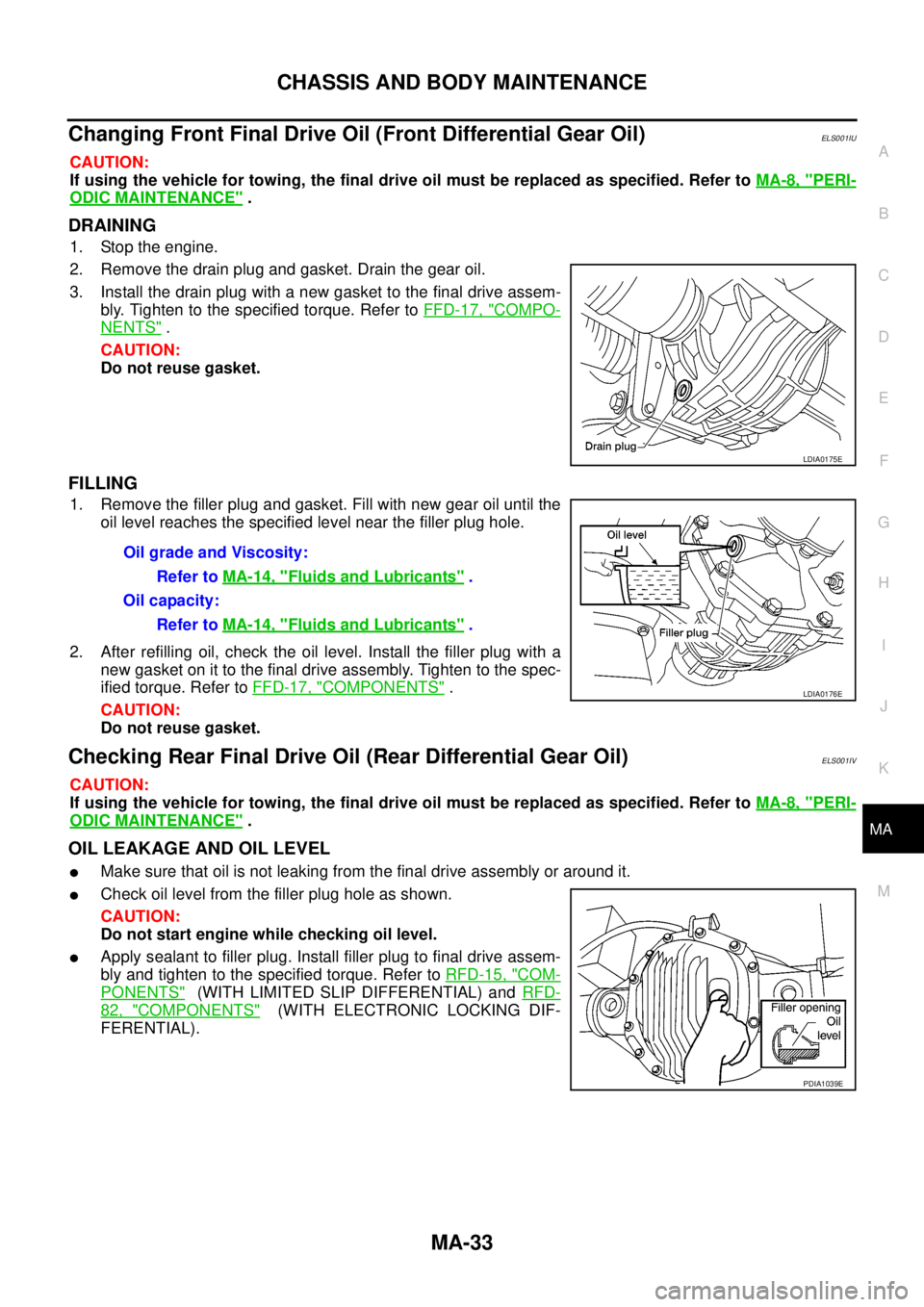
DRAINING
1. Stop the engine.
2. Remove the drain plug and gasket. Drain the gear oil.
3. Install the drain plug with a new gasket to the final drive assem-
bly. Tighten to the specified torque. Refer toFFD-17, "
COMPO-
NENTS".
CAUTION:
Do not reuse gasket.
FILLING
1. Remove the filler plug and gasket. Fill with new gear oil until the
oil level reaches the specified level near the filler plug hole.
2. After refilling oil, check the oil level. Install the filler plug with a
new gasket on it to the final drive assembly. Tighten to the spec-
ified torque. Refer toFFD-17, "
COMPONENTS".
CAUTION:
Do not reuse gasket.
Checking Rear Final Drive Oil (Rear Differential Gear Oil)ELS001IV
CAUTION:
If using the vehicle for towing, the final drive oil must be replaced as specified. Refer toMA-8, "
PERI-
ODIC MAINTENANCE".
OIL LEAKAGE AND OIL LEVEL
lMake sure that oil is not leaking from the final drive assembly or around it.
lCheck oil level from the filler plug hole as shown.
CAUTION:
Do not start engine while checking oil level.
lApply sealant to filler plug. Install filler plug to final drive assem-
bly and tighten to the specified torque. Refer toRFD-15, "
COM-
PONENTS"(WITH LIMITED SLIP DIFFERENTIAL) andRFD-
82, "COMPONENTS"(WITH ELECTRONIC LOCKING DIF-
FERENTIAL).
LDIA0175E
OilgradeandViscosity:
Refer toMA-14, "
Fluids and Lubricants".
Oil capacity:
Refer toMA-14, "
Fluids and Lubricants".
LDIA0176E
PDIA1039E
Page 2309 of 3171
MA-34
CHASSIS AND BODY MAINTENANCE
Changing Rear Final Drive Oil (Rear Differential Gear Oil)
ELS001IW
CAUTION:
If using the vehicle for towing, the final drive oil must be replaced as specified. Refer toMA-8, "
PERI-
ODIC MAINTENANCE".
DRAINING
1. Stop the engine.
2. Remove the drain plug and gasket. Drain the gear oil.
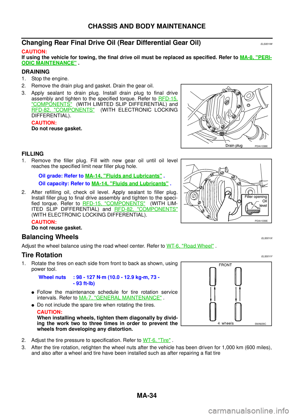
3. Apply sealant to drain plug. Install drain plug to final drive
assembly and tighten to the specified torque. Refer toRFD-15,
"COMPONENTS"(WITH LIMITED SLIP DIFFERENTIAL) and
RFD-82, "
COMPONENTS"(WITH ELECTRONIC LOCKING
DIFFERENTIAL).
CAUTION:
Do not reuse gasket.
FILLING
1. Remove the filler plug. Fill with new gear oil until oil level
reaches the specified limit near filler plug hole.
2. After refilling oil, check oil level. Apply sealant to filler plug.
Install filler plug to final drive assembly and tighten to the speci-
fied torque. Refer toRFD-15, "
COMPONENTS"(WITH LIM-
ITED SLIP DIFFERENTIAL) andRFD-82, "
COMPONENTS"
(WITH ELECTRONIC LOCKING DIFFERENTIAL).
CAUTION:
Do not reuse gasket.
Balancing WheelsELS001IX
Adjust the wheel balance using the road wheel center. Refer toWT-6, "Road Wheel".
Tire RotationELS001IY
1. Rotate the tires on each side from front to back as shown, using
power tool.
lFollow the maintenance schedule for tire rotation service
intervals. Refer toMA-7, "
GENERAL MAINTENANCE".
lDo not include the spare tire when rotating the tires.
CAUTION:
When installing wheels, tighten them diagonally by divid-
ing the work two to three times in order to prevent the
wheels from developing any distortion.
2. Adjust the tire pressure to specification. Refer toWT-6, "
Tire".
3. After the tire rotation, retighten the wheel nuts after the vehicle has been driven for 1,000 km (600 miles),
and also after a wheel and tire have been installed such as after repairing a flat tire
PDIA1038E
Oil grade: Refer toMA-14, "Fluids and Lubricants".
Oil capacity: Refer toMA-14, "
Fluids and Lubricants".
PDIA1039E
Wheel nuts : 98 - 127 N·m (10.0 - 12.9 kg-m, 73 -
- 93 ft-lb)
SMA829C
Page 2326 of 3171

M/T OIL
MT-9
D
E
F
G
H
I
J
K
L
MA
B
MT
M/T OILPFP:KLD20
Changing M/T OilECS00ID3
DRAINING
1. Start engine and let it run to warm up transmission.
2. Stop engine. Remove drain plug and gasket and then drain oil.
3. Set a gasket on drain plug and install it to transmission case. Tighten drain plug to the specified torque.
Refer toMT-19, "
Case Components".
CAUTION:
Do no reuse gasket.
FILLING
1. Remove filler plug and gasket. Fill with new oil until oil level reaches the specified limit near filler plug
mounting hole.
2. After refilling oil, check oil level. Set a gasket to filler plug, then install it to transmission case. Tighten filler
plug to the specified torque. Refer toMT-19, "
Case Components".
CAUTION:
Do no reuse gasket.
Checking M/T OilECS00ID4
OIL LEAKAGE AND OIL LEVEL
lMake sure that oil is not leaking from transmission or around it.
lCheck oil level from filler plug mounting hole as shown in the fig-
ure.
CAUTION:
Do not start engine while checking oil level.
lSet a gasket on filler plug and install it to transmission case.
Tighten filler plug to the specified torque. Refer toMT-19, "
Case
Components".
CAUTION:
Do not reuse gasket.Oil grade and viscosity: Refer toMA-14, "
Fluids and Lubricants".
Oil capacity
2WD models:
Approx. 3.99 (7 Imp pt)
4WD models:
Approx. 4.32 (7-5/8 Imp pt)
PCIB0268E
Page 2331 of 3171
MT-14
SHIFT CONTROL
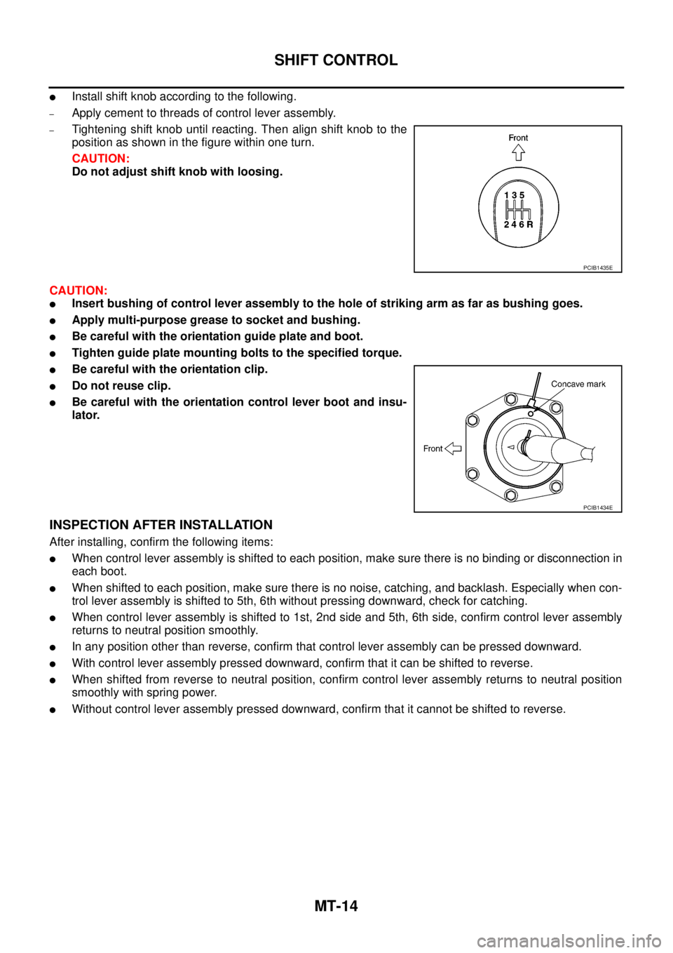
lInstall shift knob according to the following.
–Apply cement to threads of control lever assembly.
–Tightening shift knob until reacting. Then align shift knob to the
position as shown in the figure within one turn.
CAUTION:
Do not adjust shift knob with loosing.
CAUTION:
lInsert bushing of control lever assembly to the hole of striking arm as far as bushing goes.
lApply multi-purpose grease to socket and bushing.
lBe careful with the orientation guide plate and boot.
lTighten guide plate mounting bolts to the specified torque.
lBe careful with the orientation clip.
lDo not reuse clip.
lBe careful with the orientation control lever boot and insu-
lator.
INSPECTION AFTER INSTALLATION
After installing, confirm the following items:
lWhen control lever assembly is shifted to each position, make sure there is no binding or disconnection in
each boot.
lWhen shifted to each position, make sure there is no noise, catching, and backlash. Especially when con-
trol lever assembly is shifted to 5th, 6th without pressing downward, check for catching.
lWhen control lever assembly is shifted to 1st, 2nd side and 5th, 6th side, confirm control lever assembly
returns to neutral position smoothly.
lIn any position other than reverse, confirm that control lever assembly can be pressed downward.
lWith control lever assembly pressed downward, confirm that it can be shifted to reverse.
lWhen shifted from reverse to neutral position, confirm control lever assembly returns to neutral position
smoothly with spring power.
lWithout control lever assembly pressed downward, confirm that it cannot be shifted to reverse.
PCIB1435E
PCIB1434E
Page 2333 of 3171
MT-16
TRANSMISSION ASSEMBLY
TRANSMISSION ASSEMBLY
PFP:32010
Removal and Installation from VehicleECS00ID9
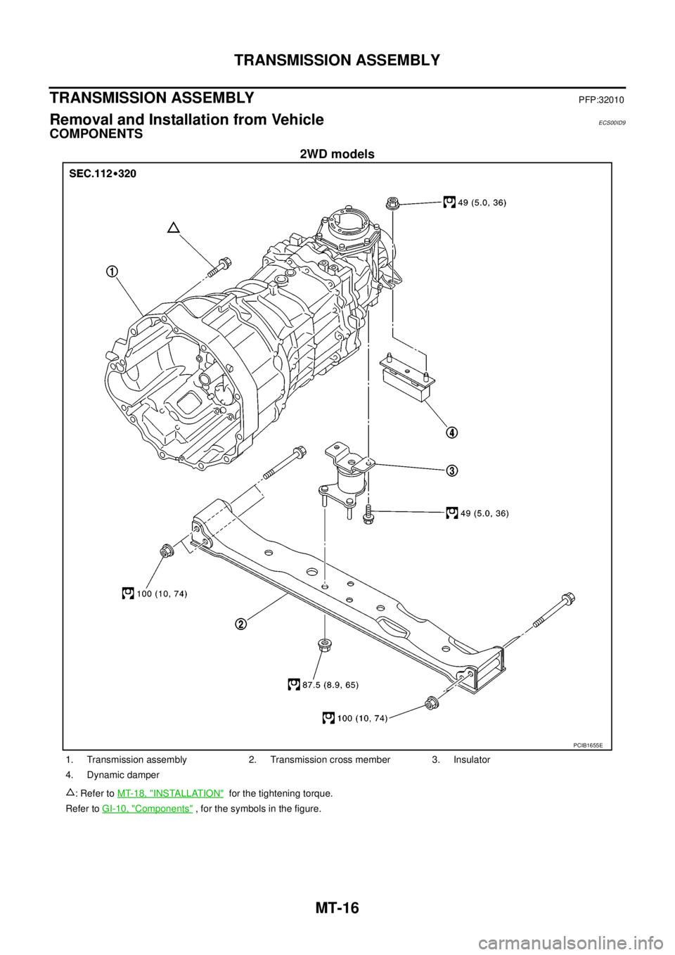
COMPONENTS
2WD models
PCIB1655E
1. Transmission assembly 2. Transmission cross member 3. Insulator
4. Dynamic damper
: Refer toMT-18, "
INSTALLATION"for the tightening torque.
Refer toGI-10, "
Components", for the symbols in the figure.