Page 2649 of 3171

PS-22
POWER STEERING GEAR AND LINKAGE
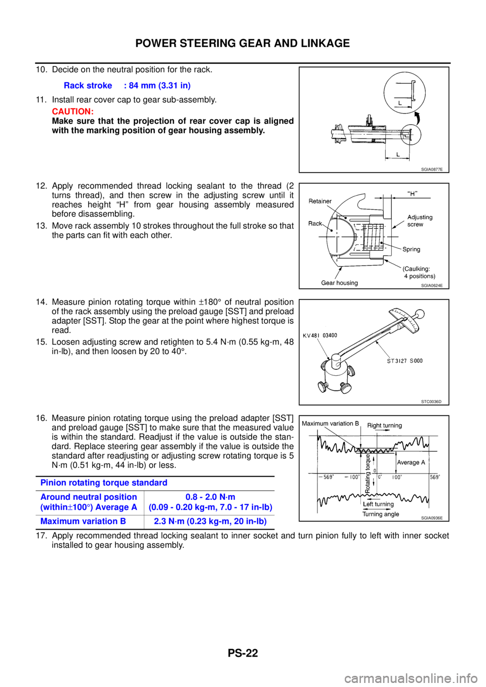
10. Decide on the neutral position for the rack.
11. Install rear cover cap to gear sub-assembly.
CAUTION:
Make sure that the projection of rear cover cap is aligned
with the marking position of gear housing assembly.
12. Apply recommended thread locking sealant to the thread (2
turns thread), and then screw in the adjusting screw until it
reaches height “H” from gear housing assembly measured
before disassembling.
13. Move rack assembly 10 strokes throughout the full stroke so that
the parts can fit with each other.
14. Measure pinion rotating torque within±180°of neutral position
of the rack assembly using the preload gauge [SST] and preload
adapter [SST]. Stop the gear at the point where highest torque is
read.
15. Loosen adjusting screw and retighten to 5.4 N·m (0.55 kg-m, 48
in-lb), and then loosen by 20 to 40°.
16. Measure pinion rotating torque using the preload adapter [SST]
and preload gauge [SST] to make sure that the measured value
is within the standard. Readjust if the value is outside the stan-
dard. Replace steering gear assembly if the value is outside the
standard after readjusting or adjusting screw rotating torque is 5
N·m (0.51 kg-m, 44 in-lb) or less.
17. Apply recommended thread locking sealant to inner socket and turn pinion fully to left with inner socket
installed to gear housing assembly.Rack stroke : 84 mm (3.31 in)
SGIA0877E
SGIA0624E
STC0036D
Pinion rotating torque standard
Around neutral position
(within±100°)AverageA0.8 - 2.0 N·m
(0.09 - 0.20 kg-m, 7.0 - 17 in-lb)
Maximum variation B 2.3 N·m (0.23 kg-m, 20 in-lb)
SGIA0936E
Page 2650 of 3171
POWER STEERING GEAR AND LINKAGE
PS-23
C
D
E
F
H
I
J
K
L
MA
B
PS
18. Set dial gauge as shown in the figure. Measure vertical move-
ment of rack assembly when pinion is turned clockwise with
torque of 19.6 N·m (2.0 kg-m, 14 ft-lb). Readjust adjusting screw
angle if the measured value is outside the standard. Replace
steering gear assembly if the measured value is still outside the
standard or adjusting screw rotating torque is 5 N·m (0.51 kg-m,
44 in-lb) or less.
19. Install large end of boot to gear housing assembly.
20. Install small end of boot to inner socket boot mounting groove.
21. Install boot clamps to boots, as shown in the figure.
SGIA1147E
Measuring pointRack axial direction 5 mm (0.20 in) from housing end surface
Rack radial direction Axial direction of the adjusting screw
Vertical movement 0.265 mm (0.0104 in)
SGIA1325E
AST139
Page 2651 of 3171
PS-24
POWER STEERING GEAR AND LINKAGE
22. Crimp the large-diameter boot clamp using suitable tool.
23. Install cylinder tubes to gear housing assembly.
24. Adjust inner socket to standard length “L”, and then tighten lock
nut to the specified torque. Refer toPS-16, "
COMPONENT".
Check length of inner socket “L” again after tightening lock nut.
Make sure that the length is the standard.
CAUTION:
Adjust toe-in after this procedure. Length achieved after
toe-in adjustment is not necessary the above value.
RAC1133D
Inner socket length “L” : 79 mm (3.11 in)
SGIA0167E
Page 2653 of 3171

PS-26
POWER STEERING OIL PUMP
INSTALLATION
Installation is the reverse order of removal. For tightening torque, refer toPS-30, "HYDRAULIC LINE".
lPerform the following procedure after installing.
–Adjust belt tension. Refer toEM-12, "DRIVE BELTS".
–Bleed air. Refer toPS-6, "Air Bleeding Hydraulic System".
Disassembly and AssemblyEGS001LN
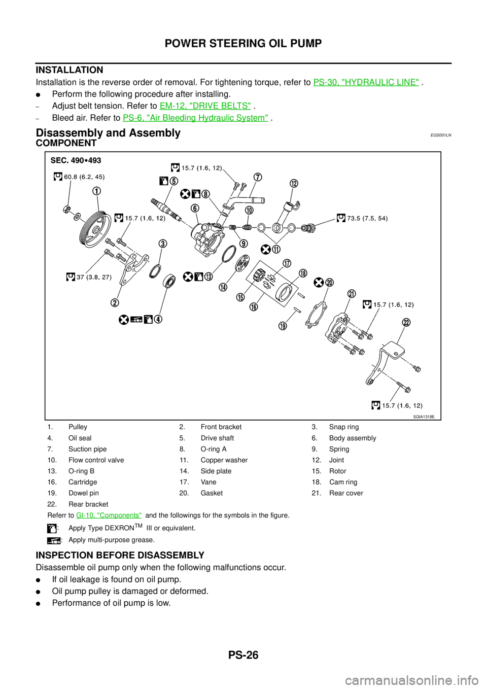
COMPONENT
INSPECTION BEFORE DISASSEMBLY
Disassemble oil pump only when the following malfunctions occur.
lIf oil leakage is found on oil pump.
lOil pump pulley is damaged or deformed.
lPerformance of oil pump is low.
1. Pulley 2. Front bracket 3. Snap ring
4. Oil seal 5. Drive shaft 6. Body assembly
7. Suction pipe 8. O-ring A 9. Spring
10. Flow control valve 11. Copper washer 12. Joint
13. O-ring B 14. Side plate 15. Rotor
16. Cartridge 17. Vane 18. Cam ring
19. Dowel pin 20. Gasket 21. Rear cover
22. Rear bracket
Referr toGI-10, "
Components"and the followings for the symbols in the figure.
:
Apply Type DEXRON
TMIII or equivalent.
:Apply multi-purpose grease.
SGIA1318E
Page 2656 of 3171
POWER STEERING OIL PUMP
PS-29
C
D
E
F
H
I
J
K
L
MA
B
PS
lWhen installing rotor, turn mark face on rotor to body assem-
bly.
7. Install vane to rotor so that arc of vane faces cam ring side.
8. Check if drive shaft turns smoothly.
9. Install gasket to body assembly.
10. Install rear cover to body assembly, and then tighten mounting
bolts to the specified torque.
11. Install rear bracket to body assembly, and tighten the mounting
bolts to the specified torque.
12. Install front bracket to body assembly, and tighten the mounting
bolts to the specified torque.
13. Install pulley and washer to drive shaft, and then tighten lock nut
at the specified torque.
14. Install spring, flow control valve, copper washer, joint and eye-
bolt to body assembly. Then tighten eye-bolt to the specified
torque.
15. Apply recommended fluid to O-ring A, and then install O-ring A to body assembly.
16. Install suction pipe to body assembly.
SGIA0874E
SGIA0613E
SGIA0425E
Page 2660 of 3171
HYDRAULIC LINE
PS-33
C
D
E
F
H
I
J
K
L
MA
B
PS
Removal and InstallationEGS001LQ
lInsert hose securely until it contacts tube spool.
CAUTION:
Do not apply fluid.
lInstall eye-bolt with eye-joint (assembled to high-pressure hose)
protrusion facing with pump side cutout, and then tighten it to
the specified torque after tightening by hand.
10. Eye-joint (assembled to
high pressure side hose)11. O-ring 12. Low pressure piping
13. High pressure piping
Refer toGI-9, "
HOW TO USE THIS MANUAL"and the followings for the symbols in the figure.
:
Apply Type DEXRON
TMIII or equivalent.
SGIA0514E
SGIA0515E
Page 2661 of 3171

PS-34
SERVICE DATA AND SPECIFICATIONS (SDS)
SERVICE DATA AND SPECIFICATIONS (SDS)
PFP:00030
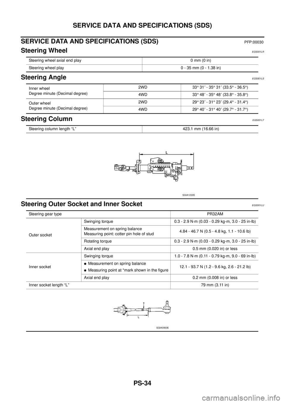
Steering WheelEGS001LR
Steering AngleEGS001LS
Steering ColumnEGS001LT
Steering Outer Socket and Inner SocketEGS001LU
Steering wheel axial end play 0 mm (0 in)
Steering wheel play 0 - 35 mm (0 - 1.38 in)
Inner wheel
Degree minute (Decimal degree)2WD 33°31¢-35°31¢(33.5°- 36.5°)
4WD 33°48¢-35°48¢(33.8°- 35.8°)
Outer wheel
Degree minute (Decimal degree)2WD 29°23¢-31°23¢(29.4°- 31.4°)
4WD 29°40¢-31°40¢(29.7°- 31.7°)
Steering column length “L” 423.1 mm (16.66 in)
SGIA1222E
Steering gear typePR32AM
Outer socketSwinging torque 0.3 - 2.9 N·m (0.03 - 0.29 kg-m, 3.0 - 25 in-lb)
Measurement on spring balance
Measuring point: cotter pin hole of stud4.84 - 46.7 N (0.5 - 4.8 kg, 1.1 - 10.6 lb)
Rotating torque 0.3 - 2.9 N·m (0.03 - 0.29 kg-m, 3.0 - 25 in-lb)
Axial end play 0.5 mm (0.020 in) or less
Inner socketSwinging torque 1.0 - 7.8 N·m (0.11 - 0.79 kg-m, 9.0 - 69 in-lb)
lMeasurement on spring balance
lMeasuring point at *mark shown in the figure12.1 - 93.7 N (1.2 - 9.6 kg, 2.6 - 21.2 lb)
Axial end play 0.2 mm (0.008 in) or less
Inner socket length “L”79 mm (3.11 in)
SGIA0950E
Page 2669 of 3171
RAX-6
[M226]
ON-VEHICLE SERVICE
ON-VEHICLE SERVICE
PFP:00000
Rear Axle PartsEDS003HX
lCheck the axle parts for excessive play, wear, and damage. Replace as necessary.
lShake each rear wheel to check for excessive play. Repair as
necessary
lRetighten all nuts and bolts to the specified torque. Refer to
RAX-7, "
AXLE SHAFT".
Rear Axle BearingEDS003HY
lCheck that the axle shaft bearing operates smoothly. Replace as necessary.
SMA525A