Page 2335 of 3171

MT-18
TRANSMISSION ASSEMBLY
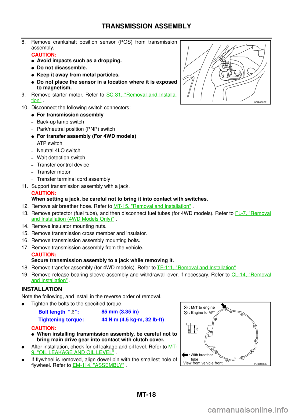
8. Remove crankshaft position sensor (POS) from transmission
assembly.
CAUTION:
lAvoid impacts such as a dropping.
lDo not disassemble.
lKeep it away from metal particles.
lDo not place the sensor in a location where it is exposed
to magnetism.
9. Remove starter motor. Refer toSC-31, "
Removal and Installa-
tion".
10. Disconnect the following switch connectors:
lFor transmission assembly
–Back-up lamp switch
–Park/neutral position (PNP) switch
lFor transfer assembly (For 4WD models)
–AT P s w i t c h
–Neutral 4LO switch
–Wait detection switch
–Transfer control device
–Transfer motor
–Transfer terminal cord assembly
11. Support transmission assembly with a jack.
CAUTION:
When setting a jack, be careful not to bring it into contact with switches.
12. Remove air breather hose. Refer toMT-15, "
Removal and Installation".
13. Remove protector (fuel tube), and then disconnect fuel tubes (for 4WD models). Refer toFL-7, "
Removal
and Installation (4WD Models Only)".
14. Remove insulator mounting nuts.
15. Remove transmission cross member and insulator.
16. Remove transmission assembly mounting bolts.
17. Remove transmission assembly from the vehicle.
CAUTION:
Secure transmission assembly to a jack while removing it.
18. Remove transfer assembly (for 4WD models). Refer toTF-111, "
Removal and Installation".
19. Remove release bearing sleeve assembly and withdrawal lever, if necessary. Refer toCL-14, "
Removal
and Installation".
INSTALLATION
Note the following, and install in the reverse order of removal.
lTighten the bolts to the specified torque.
CAUTION:
lWhen installing transmission assembly, be careful not to
bring main drive gear into contact with clutch cover.
lAfter installation, check for oil leakage and oil level. Refer toMT-
9, "OIL LEAKAGE AND OIL LEVEL".
lIf flywheel is removed, align dowel pin with the smallest hole of
flywheel. Refer toEM-114, "
ASSEMBLY".
LCIA0367E
Bolt length “ ”:85 mm (3.35 in)
Tightening torque: 44 N·m (4.5 kg-m, 32 lb-ft)
PCIB1603E
Page 2368 of 3171
TRANSMISSION ASSEMBLY
MT-51
D
E
F
G
H
I
J
K
L
MA
B
MT
b. Selectandinstallasnapringtomaindrivegearbearingsothat
the end play comes within the standard value. Refer toMT-68,
"Snap Rings".
CAUTION:
Do not reuse snap ring.
16. Install breather to adapter plate.
CAUTION:
lDo not reuse breather.
lBe careful with the orientation breather.
17. Install magnet to adapter plate.
CAUTION:
Be careful with the orientation magnet.
18. Install baffle plate to adapter plate, and then tighten mounting
bolt to the specified torque. Refer toMT-19, "
Case Components"
.
19. Install main drive gear assembly, mainshaft assembly and counter gear assembly according to the follow-
ing.End play: 0 - 0.10 mm (0 - 0.004 in)
PCIB0484E
PCIB1242E
PCIB1240E
PCIB1241E
Page 2370 of 3171
TRANSMISSION ASSEMBLY
MT-53
D
E
F
G
H
I
J
K
L
MA
B
MT
a. Instal bearing retainer to adapter plate.
b. Apply recommended thread locking sealant to threads of bolts,
and then tighten mounting bolts to the specified torque. Refer to
MT-19, "
Case Components".
25. Install reverse synchronizer hub assembly according to the following.
a. Install reverse coupling sleeve to reverse synchronizer hub.
CAUTION:
lDo not reuse reverse coupling sleeve and reverse synchronizer hub.
lReplace reverse coupling sleeve and reverse synchronizer hub as a set.
lBe careful with the orientation reverse coupling sleeve.
lBe careful with the orientation reverse synchronizer hub.
b. Install spread springs to shifting inserts to reverse synchronizer
hub.
CAUTION:
lDo not install spread spring hook onto the same shifting
insert.
PCIB1238E
PCIB0617E
PCIB1267E
SCIA1600E
Page 2374 of 3171
TRANSMISSION ASSEMBLY
MT-57
D
E
F
G
H
I
J
K
L
MA
B
MT
4. Install 5th-6th control lever to adapter plate, and then tighten
mounting bolts to the specified torque. Refer toMT-23, "
Shift
Control Components".
CAUTION:
Install 5th-6th control lever with projection side at upward.
5. Install 5th-6th fork rod according to the following.
a. Install 5th-6th fork bracket and 5th-6th fork rod to adapter plate.
b. Install retaining pin onto 5th-6th fork bracket using a pin punch.
CAUTION:
Do not reuse retaining pin.
6. Install check balls to adapter plate.
CAUTION:
Apply gear oil to check ball.
7. Install reverse fork rod according to the following.
a. Install reverse shift fork to reverse coupling sleeve.
b. Install reverse fork rod to reverse shift fork.
c. Install retaining pin onto reverse shift fork using a pin punch.
CAUTION:
Do not reuse retaining pin.
PCIB1233E
PCIB0239E
PCIB0148E
SCIA1447E
Page 2376 of 3171

TRANSMISSION ASSEMBLY
MT-59
D
E
F
G
H
I
J
K
L
MA
B
MT
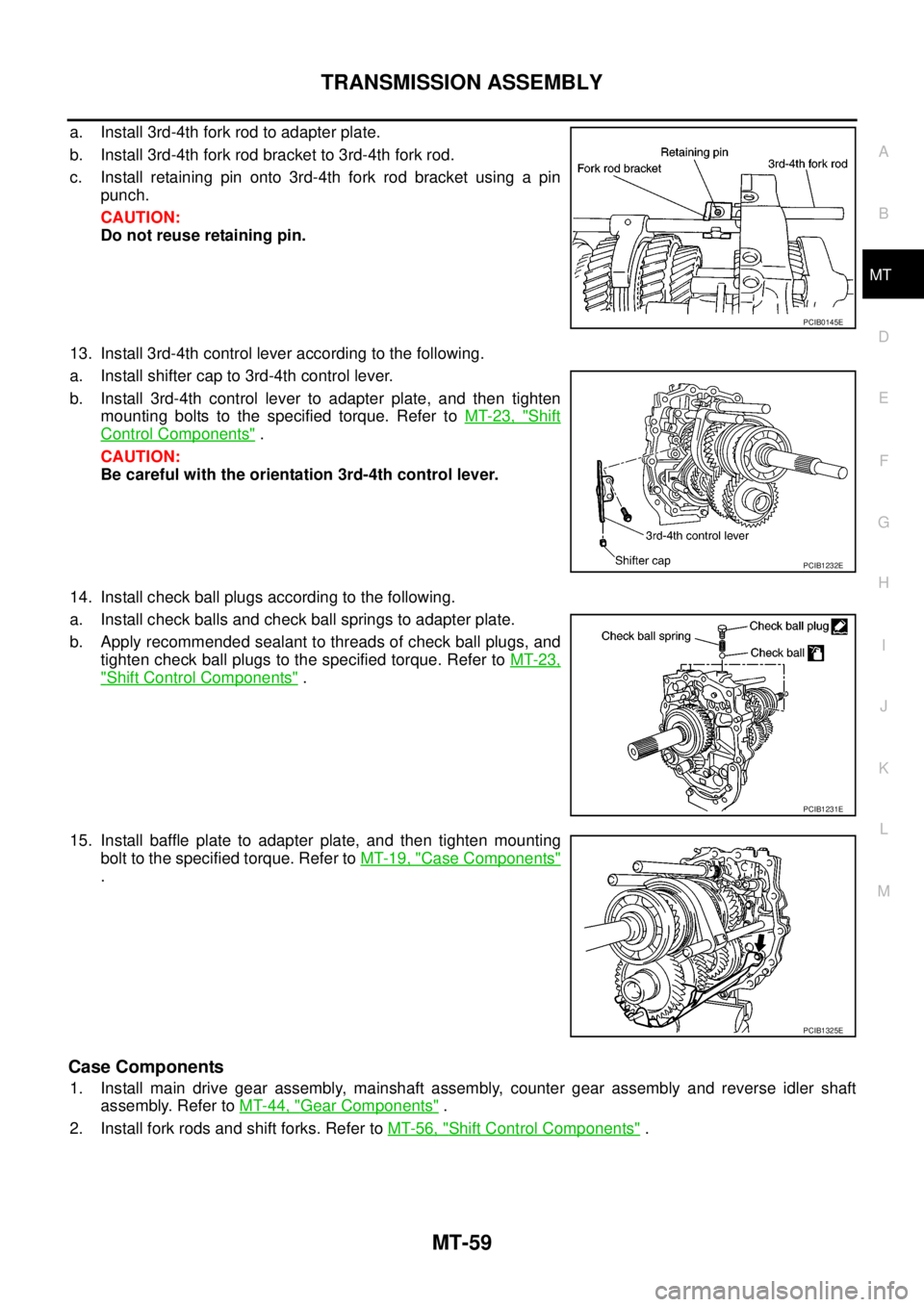
a. Install 3rd-4th fork rod to adapter plate.
b. Install 3rd-4th fork rod bracket to 3rd-4th fork rod.
c. Install retaining pin onto 3rd-4th fork rod bracket using a pin
punch.
CAUTION:
Do not reuse retaining pin.
13. Install 3rd-4th control lever according to the following.
a. Install shifter cap to 3rd-4th control lever.
b. Install 3rd-4th control lever to adapter plate, and then tighten
mounting bolts to the specified torque. Refer toMT-23, "
Shift
Control Components".
CAUTION:
Be careful with the orientation 3rd-4th control lever.
14. Install check ball plugs according to the following.
a. Install check balls and check ball springs to adapter plate.
b. Apply recommended sealant to threads of check ball plugs, and
tighten check ball plugs to the specified torque. Refer toMT-23,
"Shift Control Components".
15. Install baffle plate to adapter plate, and then tighten mounting
bolt to the specified torque. Refer toMT-19, "
Case Components"
.
Case Components
1. Install main drive gear assembly, mainshaft assembly, counter gear assembly and reverse idler shaft
assembly. Refer toMT-44, "
Gear Components".
2. Install fork rods and shift forks. Refer toMT-56, "
Shift Control Components".
PCIB0145E
PCIB1232E
PCIB1231E
PCIB1325E
Page 2378 of 3171
TRANSMISSION ASSEMBLY
MT-61
D
E
F
G
H
I
J
K
L
MA
B
MT
8. Tighten baffle plate mounting nut to the specified torque. Refer
toMT-19, "
Case Components".
9. Tighten baffle plate mounting bolt to the specified torque. Refer
toMT-19, "
Case Components".
10. Install front cover oil seal to front cover using the drift.
CAUTION:
When installing, do not incline front cover oil seal.
11. Install front cover according to the following.
SCIA1443E
PCIB1271E
Dimension “A”: 8.55 - 9.55 (0.336 - 0.376 in)
PCIB1424E
Page 2379 of 3171

MT-62
TRANSMISSION ASSEMBLY
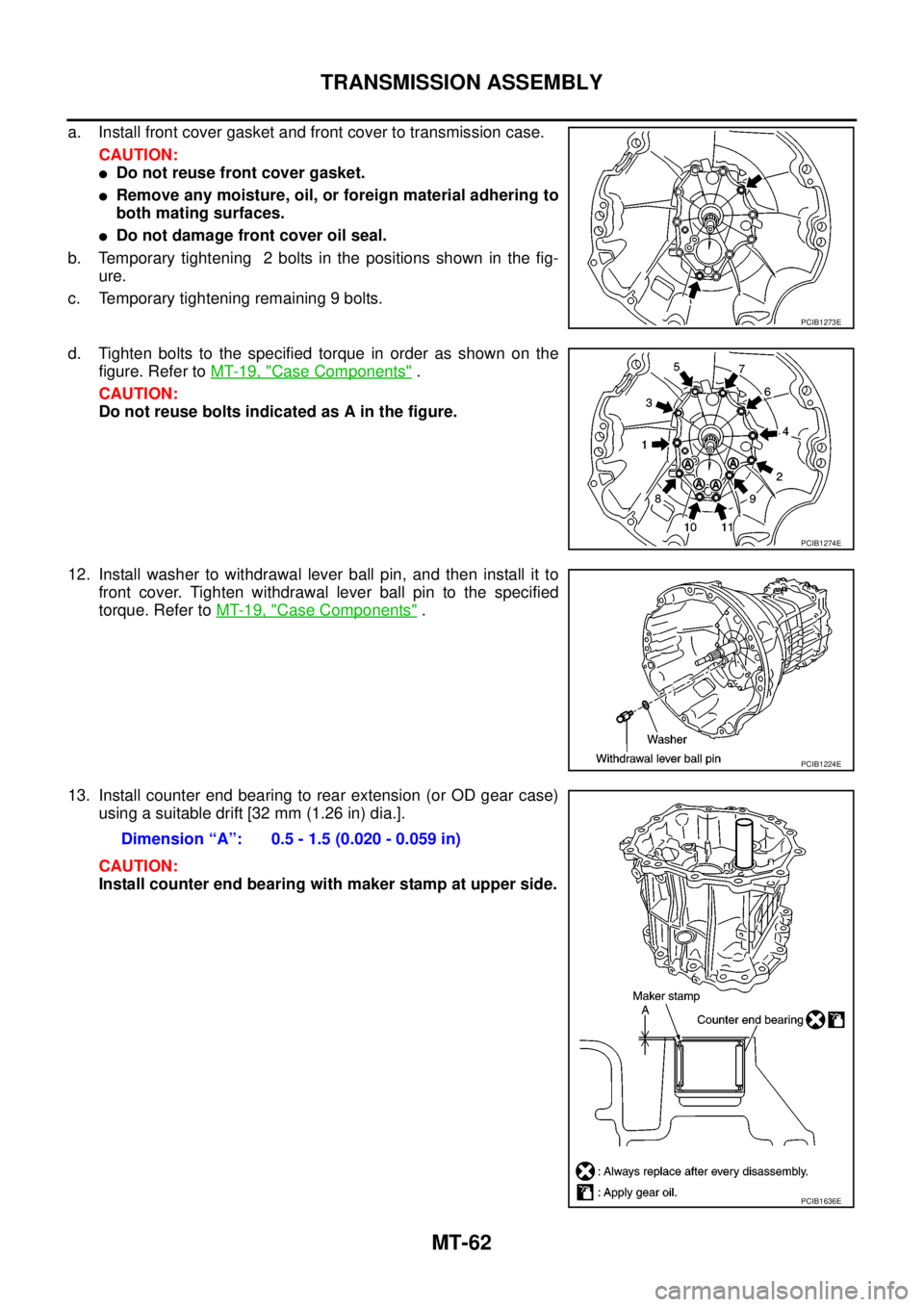
a. Install front cover gasket and front cover to transmission case.
CAUTION:
lDo not reuse front cover gasket.
lRemove any moisture, oil, or foreign material adhering to
both mating surfaces.
lDo not damage front cover oil seal.
b. Temporary tightening 2 bolts in the positions shown in the fig-
ure.
c. Temporary tightening remaining 9 bolts.
d. Tighten bolts to the specified torque in order as shown on the
figure. Refer toMT-19, "
Case Components".
CAUTION:
Do not reuse bolts indicated as A in the figure.
12. Install washer to withdrawal lever ball pin, and then install it to
front cover. Tighten withdrawal lever ball pin to the specified
torque. Refer toMT-19, "
Case Components".
13. Install counter end bearing to rear extension (or OD gear case)
using a suitable drift [32 mm (1.26 in) dia.].
CAUTION:
Install counter end bearing with maker stamp at upper side.
PCIB1273E
PCIB1274E
PCIB1224E
Dimension “A”: 0.5 - 1.5 (0.020 - 0.059 in)
PCIB1636E
Page 2380 of 3171
TRANSMISSION ASSEMBLY
MT-63
D
E
F
G
H
I
J
K
L
MA
B
MT
14. Install rear oil seal (1) to rear extension (or OD gear case) using
the drift.
CAUTION:
When installing, do not incline rear oil seal.
(B): Seal lip
15. Install dust seal (1) to rear extension using the drift (for 2WD
models).
CAUTION:
When installing, do not incline dust seal.
(B): Seal lip
16. Install rear extension oil gutter according to the following (for 2WD models).
a. Install cap to rear extension oil gutter.
b. Install rear extension oil gutter to rear extension, and then
tighten mounting bolt to specified torque. Refer toMT-19, "
Case
Components". Tool number A: ST33200000
Dimension “H
1”:
2WD models : 1.2 - 2.2 mm (0.047 - 0.087 in)
4WD models : -0.5 - 0.5 mm (-0.020 - 0.020 in)
SCIA7341E
Tool number A: KV38100500
Dimension “H
2”: 0.5 - 1.5 mm (0.020 - 0.059 in)
SCIA7342E
PCIB1221E