Page 3088 of 3171
TRANSFER ASSEMBLY
TF-121
C
E
F
G
H
I
J
K
L
MA
B
TF
2. Install the baffle plate to the front case. Tighten the bolt to the
specified torque. Refer toTF-112, "
COMPONENTS".
CAUTION:
Install baffle plate by pushing it in the direction shown
while tightening the bolt.
3. Install the input bearing to the front case, using Tool.
4. Install the snap ring to the front case.
CAUTION:
Do not reuse snap ring.
5. Install the internal gear with the groove facing up into the front
case.
6. Install the snap ring to the front case.
CAUTION:
Do not reuse snap ring.
SDIA2479E
Tool number : ST30720000
PDIA0108E
PDIA0103E
PDIA0102E
PDIA0101E
Page 3092 of 3171

TRANSFER ASSEMBLY
TF-125
C
E
F
G
H
I
J
K
L
MA
B
TF
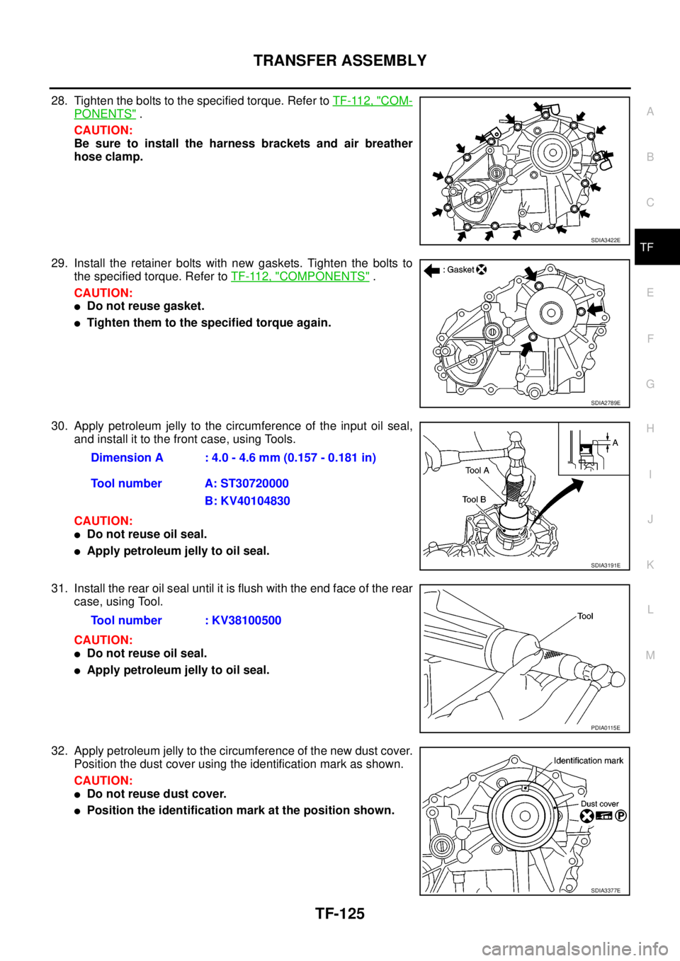
28. Tighten the bolts to the specified torque. Refer toTF-112, "COM-
PONENTS".
CAUTION:
Be sure to install the harness brackets and air breather
hose clamp.
29. Install the retainer bolts with new gaskets. Tighten the bolts to
the specified torque. Refer toTF-112, "
COMPONENTS".
CAUTION:
lDo not reuse gasket.
lTighten them to the specified torque again.
30. Apply petroleum jelly to the circumference of the input oil seal,
and install it to the front case, using Tools.
CAUTION:
lDo not reuse oil seal.
lApply petroleum jelly to oil seal.
31. Install the rear oil seal until it is flush with the end face of the rear
case, using Tool.
CAUTION:
lDo not reuse oil seal.
lApply petroleum jelly to oil seal.
32. Apply petroleum jelly to the circumference of the new dust cover.
Position the dust cover using the identification mark as shown.
CAUTION:
lDo not reuse dust cover.
lPosition the identification mark at the position shown.
SDIA3422E
SDIA2789E
Dimension A : 4.0 - 4.6 mm (0.157 - 0.181 in)
Tool number A: ST30720000
B: KV40104830
SDIA3191E
Tool number : KV38100500
PDIA0115E
SDIA3377E
Page 3093 of 3171

TF-126
TRANSFER ASSEMBLY
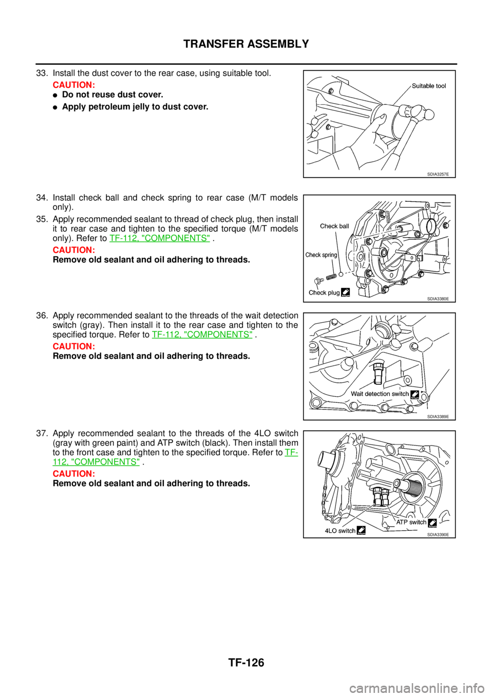
33. Install the dust cover to the rear case, using suitable tool.
CAUTION:
lDo not reuse dust cover.
lApply petroleum jelly to dust cover.
34. Install check ball and check spring to rear case (M/T models
only).
35. Apply recommended sealant to thread of check plug, then install
it to rear case and tighten to the specified torque (M/T models
only). Refer toTF-112, "
COMPONENTS".
CAUTION:
Remove old sealant and oil adhering to threads.
36. Apply recommended sealant to the threads of the wait detection
switch(gray).Theninstallittotherearcaseandtightentothe
specified torque. Refer toTF-112, "
COMPONENTS".
CAUTION:
Remove old sealant and oil adhering to threads.
37. Apply recommended sealant to the threads of the 4LO switch
(gray with green paint) and ATP switch (black). Then install them
to the front case and tighten to the specified torque. Refer toTF-
11 2 , "COMPONENTS".
CAUTION:
Remove old sealant and oil adhering to threads.
SDIA3257E
SDIA3380E
SDIA3389E
SDIA3390E
Page 3094 of 3171
TRANSFER ASSEMBLY
TF-127
C
E
F
G
H
I
J
K
L
MA
B
TF
38. Install the front oil seal until it is flush with the end face of the
front case, using Tool.
CAUTION:
lDo not reuse oil seal.
lApply petroleum jelly to oil seal.
39. Align the matching mark on the front drive shaft with the mark on
the companion flange, then install the companion flange.
40. Install the companion flange self-lock nut. Tighten to the speci-
fied torque, using Tool. Refer toTF-112, "
COMPONENTS".
CAUTION:
Do not reuse self-lock nut.
41. Install the O-ring to the transfer control device.
CAUTION:
lDo not reuse O-ring.
lApply petroleum jelly to O-ring.
42. Install the transfer control device to the rear case.
a. Turn the control shift rod fully counterclockwise using a flat-
bladed screwdriver, and then put a mark on the control shift rod.Tool number : KV38100500
PDIA0117E
SDIA2779E
Tool number : KV40104000
WDIA0219E
SDIA3378E
PDIA0119E
Page 3095 of 3171
TF-128
TRANSFER ASSEMBLY
b. Align the transfer control device shaft cutout with the mark on
the control shift rod, and install it.
NOTE:
Turn the transfer control device when the transfer control device
connection does not match.
c. Tighten the bolts to the specified torque. Refer toTF-112, "
COM-
PONENTS".
43. Install the drain plug and filler plug with new gaskets to the rear
case. Tighten to the specified torque. Refer toTF-112, "
COM-
PONENTS".
CAUTION:
Do not reuse gaskets.
PDIA0120E
SDIA2212E
Page 3110 of 3171

WHEEL AND TIRE ASSEMBLY
WT-5
C
D
F
G
H
I
J
K
L
MA
B
WT
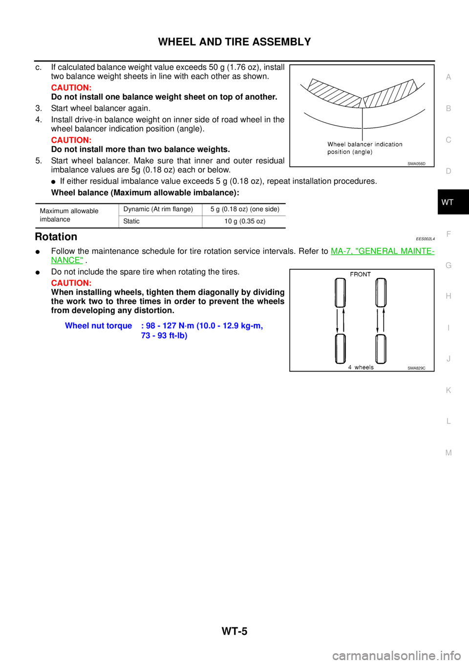
c. If calculated balance weight value exceeds 50 g (1.76 oz), install
two balance weight sheets in line with each other as shown.
CAUTION:
Do not install one balance weight sheet on top of another.
3. Start wheel balancer again.
4. Install drive-in balance weight on inner side of road wheel in the
wheel balancer indication position (angle).
CAUTION:
Do not install more than two balance weights.
5. Start wheel balancer. Make sure that inner and outer residual
imbalance values are 5g (0.18 oz) each or below.
lIf either residual imbalance value exceeds 5 g (0.18 oz), repeat installation procedures.
Wheel balance (Maximum allowable imbalance):
RotationEES002L4
lFollow the maintenance schedule for tire rotation service intervals. Refer toMA-7, "GENERAL MAINTE-
NANCE".
lDo not include the spare tire when rotating the tires.
CAUTION:
When installing wheels, tighten them diagonally by dividing
the work two to three times in order to prevent the wheels
from developing any distortion.
Maximum allowable
imbalanceDynamic (At rim flange) 5 g (0.18 oz) (one side)
Static 10 g (0.35 oz)
SMA056D
Wheel nut torque : 98 - 127 N·m (10.0 - 12.9 kg-m,
73 - 93 ft-lb)
SMA829C
Page 3145 of 3171

WW-34
FRONT WIPER AND WASHER SYSTEM
Removal and Installation of Front Wiper Arms, Adjustment of Wiper Arms Stop
Location
EKS00P5E
REMOVAL
1. Operate wiper motor, and stop it at the auto stop position.
2. Remove wiper arm mounting nuts covers.
3. Remove wiper arm mounting nuts, then remove wiper arms.
INSTALLATION
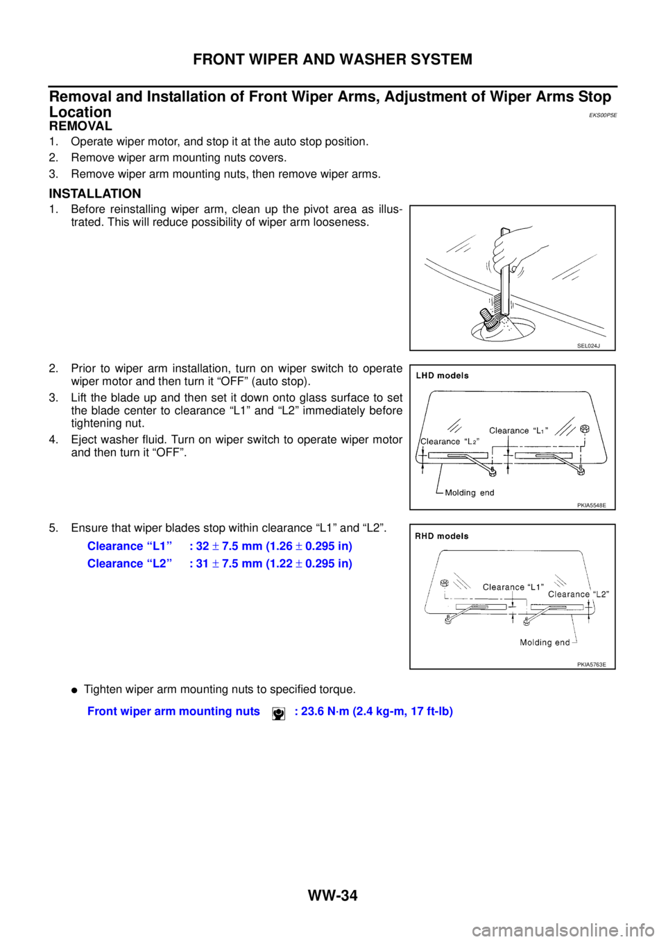
1. Before reinstalling wiper arm, clean up the pivot area as illus-
trated. This will reduce possibility of wiper arm looseness.
2. Prior to wiper arm installation, turn on wiper switch to operate
wiper motor and then turn it “OFF” (auto stop).
3. Lift the blade up and then set it down onto glass surface to set
the blade center to clearance “L1” and “L2” immediately before
tightening nut.
4. Eject washer fluid. Turn on wiper switch to operate wiper motor
and then turn it “OFF”.
5. Ensure that wiper blades stop within clearance “L1” and “L2”.
lTighten wiper arm mounting nuts to specified torque.
SEL024J
PKIA5548E
Clearance “L1” : 32±7.5 mm (1.26±0.295 in)
Clearance “L2” : 31±7.5 mm (1.22±0.295 in)
PKIA5763E
Front wiper arm mounting nuts : 23.6 N·m (2.4 kg-m, 17 ft-lb)