Page 2846 of 3171
BATTERY
SC-13
C
D
E
F
G
H
I
J
L
MA
B
SC
Removal and InstallationEKS00MZ9
Observethefollowingtoensureproperservicing.
CAUTION:
lWhen removing, remove negative terminal first. But for installation, install positive terminal first.
lTighten parts to the specified torque as shown in figure.
1. Battery fixing type 1 2. Battery fixing type 2 3. Battery 4. Battery tray
MKIB1993E
Page 2873 of 3171
SE-2
PRECAUTIONS
PRECAUTIONS
PFP:00001
Precautions for Supplemental Restraint System (SRS) “AIR BAG” and “SEAT
BELT PRE-TENSIONER”
EIS00CEB
The Supplemental Restraint System such as “AIR BAG” and “SEAT BELT PRE-TENSIONER”, used along
with a front seat belt, helps to reduce the risk or severity of injury to the driver and front passenger for certain
types of collision. Information necessary to service the system safely is included in the SRS and SB section of
this Service Manual.
WARNING:
lTo avoid rendering the SRS inoperative, which could increase the risk of personal injury or death
in the event of a collision which would result in air bag inflation, all maintenance must be per-
formed by an authorized NISSAN/INFINITI dealer.
lImproper maintenance, including incorrect removal and installation of the SRS, can lead to per-
sonal injury caused by unintentional activation of the system. For removal of Spiral Cable and Air
Bag Module, see the SRS section.
lDo not use electrical test equipment on any circuit related to the SRS unless instructed to in this
Service Manual. SRS wiring harnesses can be identified by yellow and/or orange harnesses or
harness connectors.
Precautions for WorkEIS00BAR
lWhen removing or disassembling each component, be careful not to damage or deform it. If a component
may be subject to interference, be sure to protect it with a shop cloth.
lWhen removing (disengaging) components with a screwdriver or similar tool, be sure to wrap the compo-
nent with a shop cloth or vinyl tape to protect it.
lProtect the removed parts with a shop cloth and keep them.
lReplace a deformed or damaged clip.
lIf a part is specified as a non-reusable part, always replace it with new one.
lBe sure to tighten bolts and nuts securely to the specified torque.
lAfter re-installation is completed, be sure to check that each part works normally.
lFollow the steps below to clean components.
–Water soluble foul: Dip a soft cloth into lukewarm water, and wring the water out of the cloth to wipe the
fouled area.
Then rub with a soft and dry cloth.
–Oily foul: Dip a soft cloth into lukewarm water with mild detergent (concentration: within 2 to 3%), and wipe
the fouled area.
Then dip a cloth into fresh water, and wring the water out of the cloth to wipe the detergent off. Then rub
with a soft and dry cloth.
lDo not use organic solvent such as thinner, benzene, alcohol, or gasoline.
lFor genuine leather seats, use a genuine leather seat cleaner.
Page 2973 of 3171
TF-6
PRECAUTIONS
If 4WD shift indicator lamp and 4LO indicator lamp do not indicate proper pattern, install new transfer con-
trol unit and retry the above check.
PrecautionsEDS0031B
lBefore connecting or disconnecting the transfer control unit harness connector, turn ignition
switch “OFF” and disconnect the battery cables. Battery voltage is applied to transfer control unit
even if ignition switch is turned “OFF”.
lWhen connecting or disconnecting pin connectors into or
from transfer control unit, take care not to damage pin ter-
minals (bend or break).
When connecting pin connectors make sure that there are
not any bends or breaks on transfer control unit pin termi-
nals.
lBefore replacing transfer control unit, perform transfer con-
trol unit input/output signal inspection and make sure
whether transfer control unit functions properly or not.
Refer toTF-38, "
Transfer Control Unit Input/Output Signal
Reference Values".
Service NoticeEDS0031C
lAfter overhaul refill the transfer with new transfer fluid.
lCheck the fluid level or replace the fluid only with the vehicle parked on level ground.
lDuring removal or installation, keep inside of transfer clear of dust or dirt.
lDisassemblyshouldbedoneinacleanworkarea.
lBefore proceeding with disassembly, thoroughly clean the transfer. It is important to prevent the internal
parts from becoming contaminated by dirt or other foreign matter.
lCheck for the correct installation status prior to removal or disassembly. If matchmarks are required, be
certain they do not interfere with the function of the parts when applied.
lAll parts should be carefully cleaned with a general purpose, non-flammable solvent before inspection or
reassembly.
lCheck appearance of the disassembled parts for damage, deformation, and unusual wear. Replace them
with a new ones if necessary.
lGaskets, seals and O-rings should replaced any time the transfer is disassembled.
lIn principle, tighten bolts or nuts gradually in several steps working diagonally from inside to outside. If
tightening sequence is specified, use it.
lObserve the specified torque when assembling.
lClean and flush the parts sufficiently and blow-dry them.
lBe careful not to damage sliding surfaces and mating surfaces.
lUse lint-free cloth or towels for wiping parts clean. Common shop rags can leave fibers that could interfere
with the operation of the transfer.
SEF291H
MEF040DB
Page 2979 of 3171
TF-12
TRANSFER FLUID
TRANSFER FLUID
PFP:31001
ReplacementEDS0031H
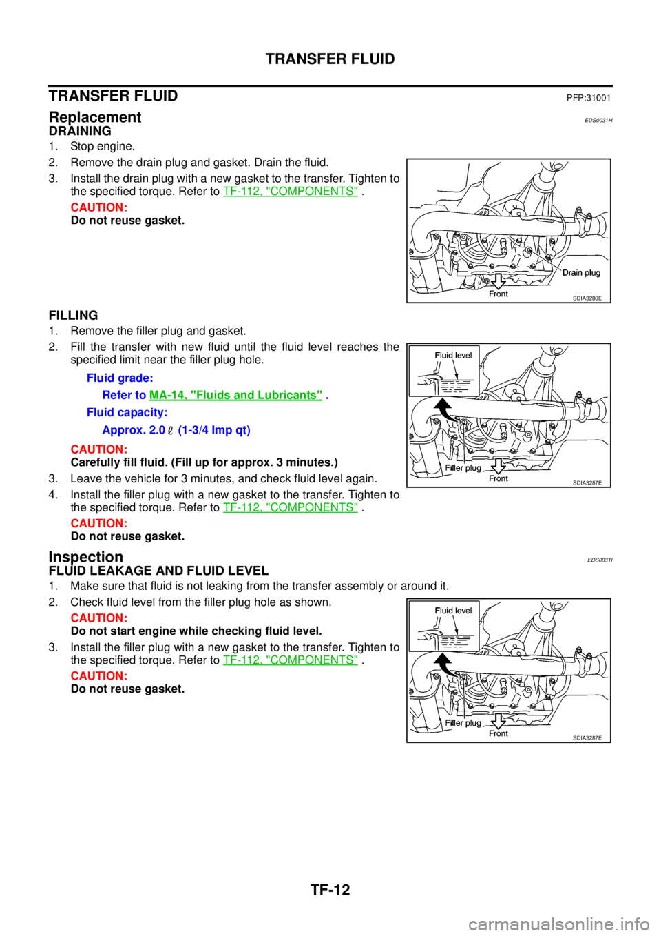
DRAINING
1. Stop engine.
2. Remove the drain plug and gasket. Drain the fluid.
3. Install the drain plug with a new gasket to the transfer. Tighten to
the specified torque. Refer toTF-112, "
COMPONENTS".
CAUTION:
Do not reuse gasket.
FILLING
1. Remove the filler plug and gasket.
2. Fill the transfer with new fluid until the fluid level reaches the
specified limit near the filler plug hole.
CAUTION:
Carefully fill fluid. (Fill up for approx. 3 minutes.)
3. Leave the vehicle for 3 minutes, and check fluid level again.
4. Install the filler plug with a new gasket to the transfer. Tighten to
the specified torque. Refer toTF-112, "
COMPONENTS".
CAUTION:
Do not reuse gasket.
InspectionEDS0031I
FLUID LEAKAGE AND FLUID LEVEL
1. Make sure that fluid is not leaking from the transfer assembly or around it.
2. Check fluid level from the filler plug hole as shown.
CAUTION:
Do not start engine while checking fluid level.
3. Install the filler plug with a new gasket to the transfer. Tighten to
the specified torque. Refer toTF-112, "
COMPONENTS".
CAUTION:
Do not reuse gasket.
SDIA3286E
Fluid grade:
Refer toMA-14, "
Fluids and Lubricants".
Fluid capacity:
Approx. 2.0 (1-3/4 Imp qt)
SDIA3287E
SDIA3287E
Page 3067 of 3171
TF-100
TRANSFER CONTROL UNIT
TRANSFER CONTROL UNIT
PFP:33084
Removal and InstallationEDS0032J
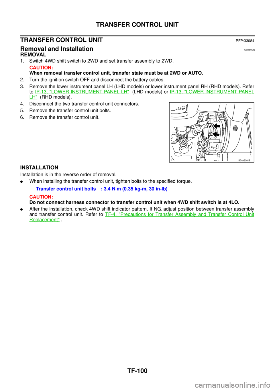
REMOVAL
1. Switch 4WD shift switch to 2WD and set transfer assembly to 2WD.
CAUTION:
When removal transfer control unit, transfer state must be at 2WD or AUTO.
2. Turn the ignition switch OFF and disconnect the battery cables.
3. Remove the lower instrument panel LH (LHD models) or lower instrument panel RH (RHD models). Refer
toIP-13, "
LOWER INSTRUMENT PANEL LH"(LHD models) orIP-13, "LOWER INSTRUMENT PANEL
LH"(RHD models).
4. Disconnect the two transfer control unit connectors.
5. Remove the transfer control unit bolts.
6. Remove the transfer control unit.
INSTALLATION
Installation is in the reverse order of removal.
lWhen installing the transfer control unit, tighten bolts to the specified torque.
CAUTION:
Do not connect harness connector to transfer control unit when 4WD shift switch is at 4LO.
lAfter the installation, check 4WD shift indicator pattern. If NG, adjust position between transfer assembly
and transfer control unit. Refer toTF-4, "
Precautions for Transfer Assembly and Transfer Control Unit
Replacement".
SDIA3201E
Transfer control unit bolts : 3.4 N·m (0.35 kg-m, 30 in-lb)
Page 3069 of 3171
TF-102
FRONT OIL SEAL
INSTALLATION
1. Install the front oil seal until it is flush with the end face of the
front case, using Tool.
CAUTION:
lDo not reuse oil seal.
lApply petroleum jelly to oil seal.
2. Align the matching mark of the front drive shaft with the match-
ing mark of the companion flange, then install the companion
flange.
3. Install the self-lock nut and tighten to the specified torque, using
Tool. Refer toTF-112, "
COMPONENTS".
CAUTION:
Do not reuse self-lock nut.
4. Install the front propeller shaft. Refer toPR-4, "
Removal and
Installation".
5. Refill the transfer with fluid and check fluid level. Refer toTF-12,
"FILLING".
6. Check the transfer for fluid leakage. Refer toTF-12, "
FLUID
LEAKAGE AND FLUID LEVEL". Tool number : KV38100500
LDIA0145E
SDIA2214E
Tool number : KV40104000
LDIA0147E
Page 3073 of 3171
TF-106
TRANSFER CONTROL DEVICE
c. Tighten the bolts to the specified torque. Refer toTF-112, "COM-
PONENTS".
3. Install the breather hose to the transfer control device.
4. Connect the transfer control device connector.
5. After the installation, check the 4WD shift indicator pattern. If
NG, adjust the position between the transfer assembly and
transfer control unit. Refer toTF-4, "
Precautions for Transfer
Assembly and Transfer Control Unit Replacement".
SDIA2212E
Page 3079 of 3171
TF-112
TRANSFER ASSEMBLY
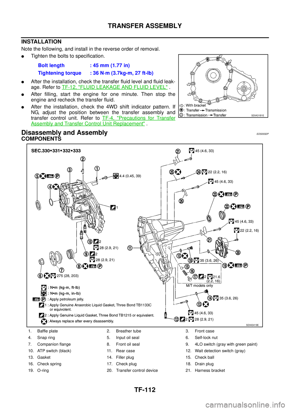
INSTALLATION
Note the following, and install in the reverse order of removal.
lTighten the bolts to specification.
lAfter the installation, check the transfer fluid level and fluid leak-
age. Refer toTF-12, "
FLUID LEAKAGE AND FLUID LEVEL".
lAfter filling, start the engine for one minute. Then stop the
engine and recheck the transfer fluid.
lAfter the installation, check the 4WD shift indicator pattern. If
NG, adjust the position between the transfer assembly and
transfer control unit. Refer toTF-4, "
Precautions for Transfer
Assembly and Transfer Control Unit Replacement".
Disassembly and AssemblyEDS0032P
COMPONENTS
Bolt length : 45 mm (1.77 in)
Tightening torque : 36 N·m (3.7kg-m, 27 ft-lb)
SDIA3181E
1. Baffle plate 2. Breather tube 3. Front case
4. Snap ring 5. Input oil seal 6. Self-lock nut
7. Companion flange 8. Front oil seal 9. 4LO switch (gray with green paint)
10. ATP switch (black) 11. Rear case 12. Wait detection switch (gray)
13. Gasket 14. Filler plug 15. Check ball
16. Check spring 17. Check plug 18. Drain plug
19. O-ring 20. Transfer control device 21. Harness bracket
SDIA3419E