2005 NISSAN NAVARA Engine lubrication system
[x] Cancel search: Engine lubrication systemPage 1 of 3171
MODELD40 SERIES
2005 NISSAN EUROPE S.A.S.
All rights reserved. No part of this Electronic Service Manual may be reproduced or stored in a retrieval system, or transmitted in any
form, or by any means, electronic, mechanical, photocopying, recording or otherwise, without the prior written permission of Nissan
Europe S.A.S., Paris, France.
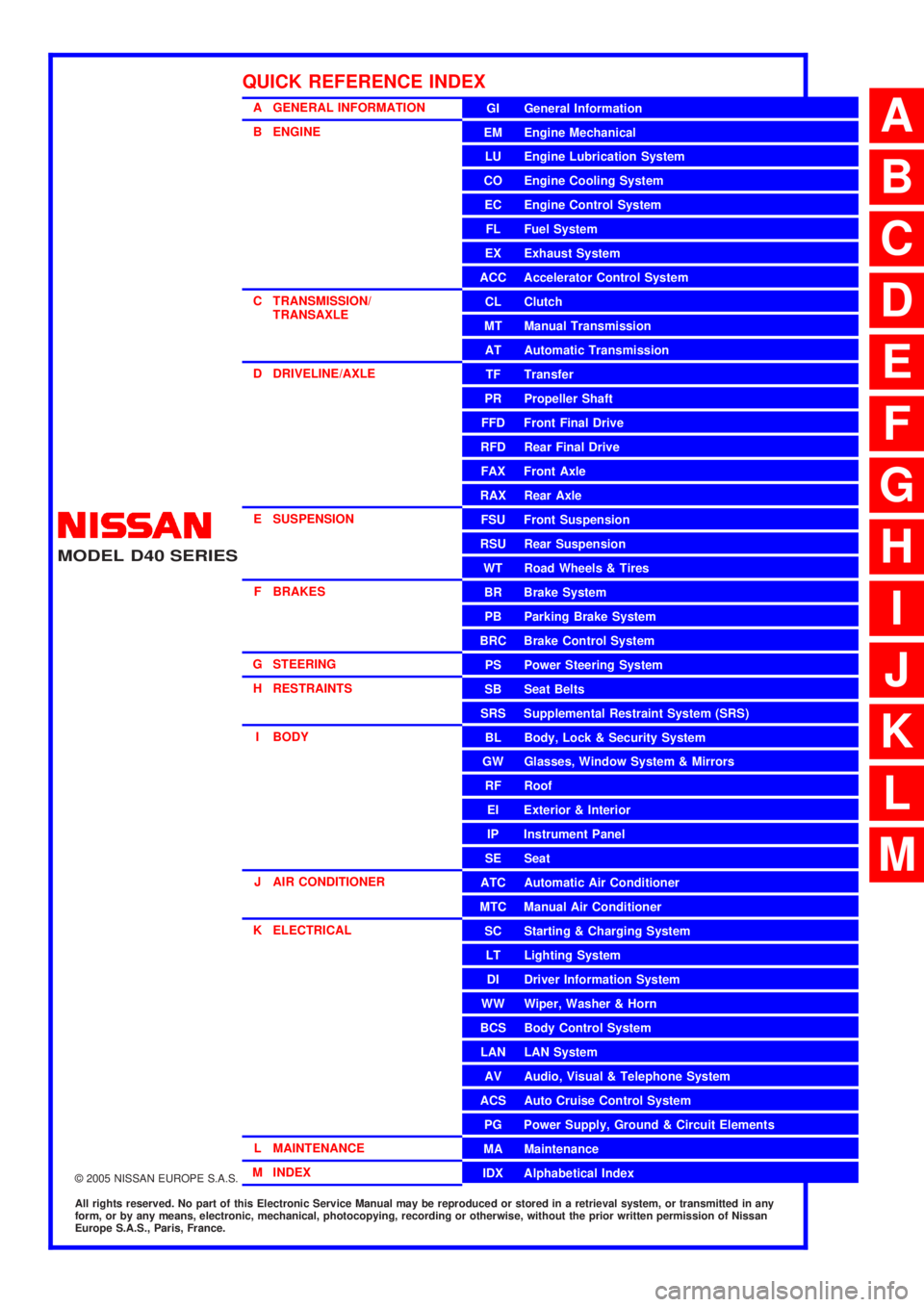
A GENERAL INFORMATION
B ENGINE
C TRANSMISSION/TRANSAXLE
D DRIVELINE/AXLE
E SUSPENSION F BRAKES
G STEERING H RESTRAINTS
I BODY
J AIR CONDITIONER
K ELECTRICAL
L MAINTENANCE
M INDEXGI General Information
EM Engine Mechanical
LU Engine Lubrication System
CO Engine Cooling System
EC Engine Control System
FL Fuel System
EX Exhaust System
ACC Accelerator Control System
CL Clutch
MTManualTransmission
AT Automatic Transmission
TF Transfer
PR Propeller Shaft
FFD Front Final Drive
RFD Rear Final Drive
FAX Front Axle
RAX Rear Axle
FSU Front Suspension
RSU Rear Suspension
WT Road Wheels & Tires
BR Brake System
PB Parking Brake System
BRC Brake Control System
PS Power Steering System
SB Seat Belts
SRS Supplemental Restraint System (SRS)
BL Body, Lock & Security System
GW Glasses, Window System & Mirrors
RF Roof
EI Exterior & Interior
IP Instrument Panel
SE Seat
ATC Automatic Air Conditioner
MTC Manual Air Conditioner
SC Starting & Charging System
LT Lighting System
DI Driver Information System
WW Wiper, Washer & Horn
BCS Body Control System
LAN LAN System
AV Audio, Visual & Telephone System
ACS Auto Cruise Control System
PG Power Supply, Ground & Circuit Elements
MA Maintenance
IDX Alphabetical Index
QUICK REFERENCE INDEX
A
B
C
D
E
F
G
H
I
J
K
L
M
Page 41 of 3171
A/T CONTROL SYSTEM
AT-33
D
E
F
G
H
I
J
K
L
MA
B
AT
Control ValveECS00FWP
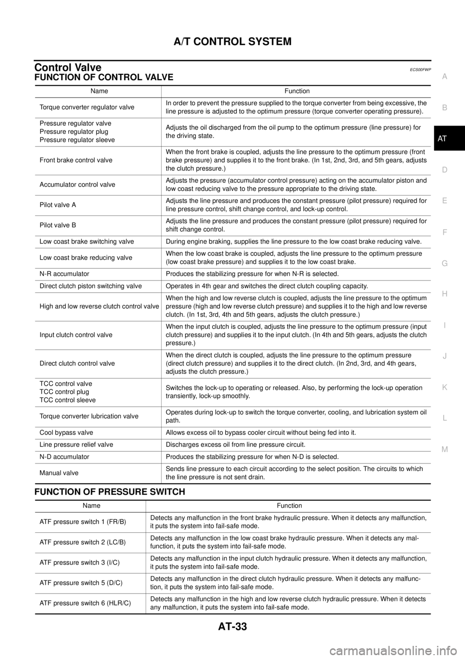
FUNCTION OF CONTROL VALVE
FUNCTION OF PRESSURE SWITCH
Name Function
Torque converter regulator valveIn order to prevent the pressure supplied to the torque converter from being excessive, the
line pressure is adjusted to the optimum pressure (torque converter operating pressure).
Pressure regulator valve
Pressure regulator plug
Pressure regulator sleeveAdjusts the oil discharged from the oil pump to the optimum pressure (line pressure) for
the driving state.
Front brake control valveWhen the front brake is coupled, adjusts the line pressure to the optimum pressure (front
brake pressure) and supplies it to the front brake. (In 1st, 2nd, 3rd, and 5th gears, adjusts
theclutchpressure.)
Accumulator control valveAdjusts the pressure (accumulator control pressure) acting on the accumulator piston and
low coast reducing valve to the pressure appropriate to the driving state.
Pilot valve AAdjusts the line pressure and produces the constant pressure (pilot pressure) required for
line pressure control, shift change control, and lock-up control.
Pilot valve BAdjusts the line pressure and produces the constant pressure (pilot pressure) required for
shift change control.
Low coast brake switching valve During engine braking, supplies the line pressure to the low coast brake reducing valve.
Low coast brake reducing valveWhen the low coast brake is coupled, adjusts the line pressure to the optimum pressure
(low coast brake pressure) and supplies it to the low coast brake.
N-R accumulator Produces the stabilizing pressure for when N-R is selected.
Direct clutch piston switching valve Operates in 4th gear and switches the direct clutch coupling capacity.
High and low reverse clutch control valveWhen the high and low reverse clutch is coupled, adjusts the line pressure to the optimum
pressure (high and low reverse clutch pressure) and supplies it to the high and low reverse
clutch. (In 1st, 3rd, 4th and 5th gears, adjusts the clutch pressure.)
Input clutch control valveWhen the input clutch is coupled, adjusts the line pressure to the optimum pressure (input
clutch pressure) and supplies it to the input clutch. (In 4th and 5th gears, adjusts the clutch
pressure.)
Direct clutch control valveWhen the direct clutch is coupled, adjusts the line pressure to the optimum pressure
(direct clutch pressure) and supplies it to the direct clutch. (In 2nd, 3rd, and 4th gears,
adjusts the clutch pressure.)
TCC control valve
TCC control plug
TCC control sleeveSwitches the lock-up to operating or released. Also, by performing the lock-up operation
transiently, lock-up smoothly.
Torque converter lubrication valveOperates during lock-up to switch the torque converter, cooling, and lubrication system oil
path.
Cool bypass valve Allows excess oil to bypass cooler circuit without being fed into it.
Line pressure relief valve Discharges excess oil from line pressure circuit.
N-D accumulator Produces the stabilizing pressure for when N-D is selected.
Manual valveSends line pressure to each circuit according to the select position. The circuits to which
the line pressure is not sent drain.
Name Function
ATFpressureswitch1(FR/B)Detects any malfunction in the front brake hydraulic pressure. When it detects any malfunction,
it puts the system into fail-safe mode.
ATFpressureswitch2(LC/B)Detects any malfunction in the low coast brake hydraulic pressure. When it detects any mal-
function, it puts the system into fail-safe mode.
ATFpressureswitch3(I/C)Detects any malfunction in the input clutch hydraulic pressure. When it detects any malfunction,
it puts the system into fail-safe mode.
ATF pressure switch 5 (D/C)Detects any malfunction in the direct clutch hydraulic pressure. When it detects any malfunc-
tion, it puts the system into fail-safe mode.
ATF pressure switch 6 (HLR/C)Detects any malfunction in the high and low reverse clutch hydraulic pressure. When it detects
any malfunction, it puts the system into fail-safe mode.
Page 1757 of 3171
IDX-5
A
C
D
E
F
G
H
I
J
K
L B
IDX
ALPHABETICAL INDEX
HSEAT - Wiring diagram .......................SE-14,SE-17
I
IATS - Wiring diagram .....................................EC-100
Identification plate ...............................................GI-57
Idle speed ..........................................................EC-38
Ignition key hole illumination .............................LT-145
ILL - Wiring diagram .........................................LT-166
Illumination .......................................................LT-162
In vehicle sensor ...........................ATC-108,ATC-118
INJE/PW - Wiring diagram ...............................EC-284
INJECT - Wiring diagram .....EC-128,EC-240,EC-289
Injection nozzle .......EM-44,EC-123,EC-125,EC-237
Injector adjustment value ...................EC-271,EC-273
Injector adjustment value registration ................EC-25
Input clutch solenoid valve .................AT-132,AT-134
Instrument panel ..................................................IP-10
INT/V - Wiring diagram ....................................EC-315
Intake air control valve control solenoid valve .EC-314
Intake air temperature sensor ............................EC-98
Intake door control linkage adjustment ............ATC-79
Intake door motor ..........ATC-77,ATC-129,MTC-109
Intake manifold ..................................................EM-20
Intake sensor ..ATC-114,ATC-120,MTC-95,MTC-99
Interior .................................................................EI-33
Interior lamp ......................................................LT-145
Interior lamp on-off control ................................LT-145
IPDM (Intelligent power distribution module engine
room) .................................................................PG-14
ISO 15031-2 Terminology ..................................GI-61
J
Jacking points .....................................................GI-52
K
Key illumination ................................................LT-145
KEYLES - Wiring diagram ..................................BL-93
L
Leaf spring (rear) ..............................................RSU-7
Length (Dimensions) ..........................................GI-60
License lamp ....................................................LT-125
Lifting points .......................................................GI-52
Line pressure solenoid valve ...........................AT-114
Line pressure test (A/T) .....................................AT-44
Liquid gasket application ................EM-5,LU-2,CO-2
Location of electrical units .................................PG-71
Low coast brake solenoid valve ..........AT-152,AT-154
Lubricant (R134a) A/C ......................ATC-24,MTC-24
Lubricants ..........................................................MA-14
Lubrication circuit (engine) ..................................LU-4
Lubrication oil A/C ............................ATC-24,MTC-24
Lubrication-locks, hinges and hood latches .......MA-39
M
MAFS - Wiring diagram .....................................EC-94
Magnet clutch .ATC-87,ATC-143,MTC-79,MTC-123
MAIN - Wiring diagram ......................................EC-72
Main drive gear (M/T) ........................................MT-21
Mainshaft (M/T) ..................................................MT-21
Major overhaul (Final drive)FFD-17,RFD-15,RFD-82
Major overhaul (Transfer) ................................TF-112
Malfunction indicator (MI) ..................................EC-28
Map lamp ..........................................................LT-145
Mass air flow sensor (MAFS) .............................EC-92
Master cylinder (brake) ......................................BR-17
Master cylinder (clutch) ........................................CL-9
Meter .....................................................................DI-4
METER - Wiring diagram ....................................DI-10
MI & data link connectors circuit ......................EC-354
MIL/DL - Wiring diagram ..................................EC-354
Mode door control linkage adjustment ............ATC-65,
MTC-59
Mode door motor ............ATC-63,ATC-130,MTC-58,
MTC-110
Model variation ...................................................GI-56
Multiport fuel injection precautions .......................GI-6
N
NATS - Wiring diagram ....................................BL-173
NATS (Nissan anti-theft system) precautions .......GI-3
NVH troubleshooting (AX) .................................FAX-4
NVH troubleshooting (BR) ...................................BR-5
NVH troubleshooting (EM) ................................EM-10
NVH troubleshooting (Final drive) ........FFD-6,RFD-7,
RFD-39
NVH troubleshooting (M/T) ..................................MT-6
NVH troubleshooting (Propeller shaft) .................PR-2
NVH troubleshooting (ST) ....................................PS-5
NVH troubleshooting (Transfer) .........................TF-11
NVH troubleshooting (WT)NVH troubleshooting (WT) .
WT-2
O
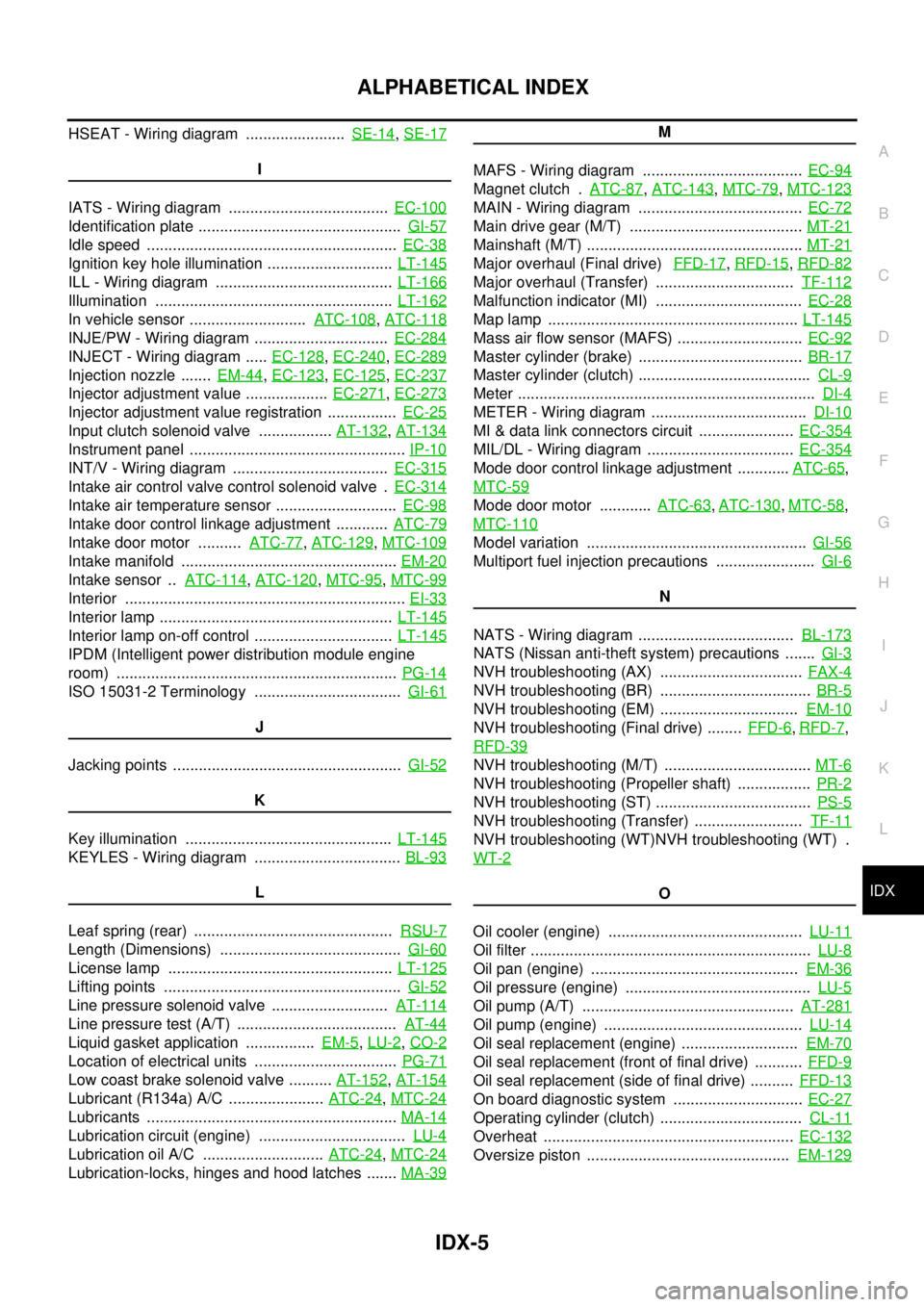
Oil cooler (engine) .............................................LU-11
Oil filter .................................................................LU-8
Oil pan (engine) ................................................EM-36
Oil pressure (engine) ...........................................LU-5
Oil pump (A/T) .................................................AT-281
Oil pump (engine) ..............................................LU-14
Oil seal replacement (engine) ...........................EM-70
Oil seal replacement (front of final drive) ...........FFD-9
Oil seal replacement (side of final drive) ..........FFD-13
On board diagnostic system ..............................EC-27
Operating cylinder (clutch) .................................CL-11
Overheat ..........................................................EC-132
Oversize piston ...............................................EM-129
Page 2258 of 3171
LU-1
ENGINE LUBRICATION SYSTEM
B ENGINE
CONTENTS
C
D
E
F
G
H
I
J
K
L
M
SECTIONLU
A
LU
ENGINE LUBRICATION SYSTEM
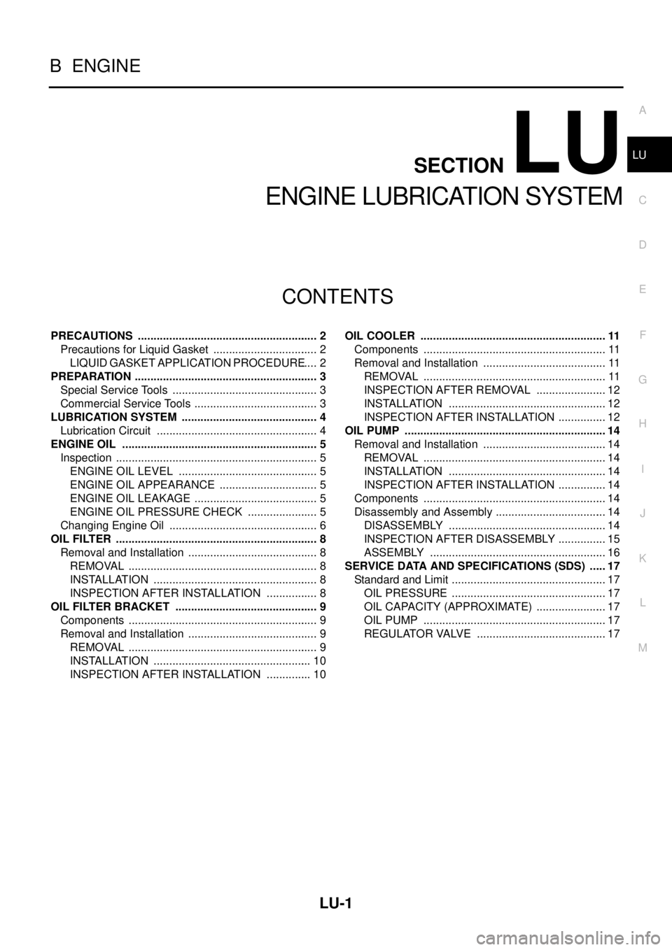
PRECAUTIONS .......................................................... 2
Precautions for Liquid Gasket .................................. 2
LIQUID GASKET APPLICATION PROCEDURE..... 2
PREPARATION ........................................................... 3
Special Service Tools ............................................... 3
Commercial Service Tools ........................................ 3
LUBRICATION SYSTEM ............................................ 4
Lubrication Circuit .................................................... 4
ENGINE OIL ............................................................... 5
Inspection ................................................................. 5
ENGINE OIL LEVEL ............................................. 5
ENGINE OIL APPEARANCE ................................ 5
ENGINE OIL LEAKAGE ........................................ 5
ENGINE OIL PRESSURE CHECK ....................... 5
Changing Engine Oil ................................................ 6
OIL FILTER ................................................................. 8
Removal and Installation .......................................... 8
REMOVAL ............................................................. 8
INSTALLATION ..................................................... 8
INSPECTION AFTER INSTALLATION ................. 8
OIL FILTER BRACKET .............................................. 9
Components ............................................................. 9
Removal and Installation .......................................... 9
REMOVAL ............................................................. 9
INSTALLATION ................................................... 10
INSPECTION AFTER INSTALLATION ............... 10OIL COOLER ............................................................ 11
Components ........................................................... 11
Removal and Installation ........................................ 11
REMOVAL ........................................................... 11
INSPECTION AFTER REMOVAL ....................... 12
INSTALLATION ................................................... 12
INSPECTION AFTER INSTALLATION ................ 12
OIL PUMP ................................................................. 14
Removal and Installation ........................................ 14
REMOVAL ........................................................... 14
INSTALLATION ................................................... 14
INSPECTION AFTER INSTALLATION ................ 14
Components ........................................................... 14
Disassembly and Assembly .................................... 14
DISASSEMBLY ................................................... 14
INSPECTION AFTER DISASSEMBLY ................ 15
ASSEMBLY ......................................................... 16
SERVICE DATA AND SPECIFICATIONS (SDS) ...... 17
Standard and Limit .................................................. 17
OIL PRESSURE .................................................. 17
OIL CAPACITY (APPROXIMATE) ....................... 17
OIL PUMP ........................................................... 17
REGULATOR VALVE .......................................... 17
Page 2282 of 3171
GENERAL MAINTENANCE
MA-7
C
D
E
F
G
H
I
J
K
MA
B
MA
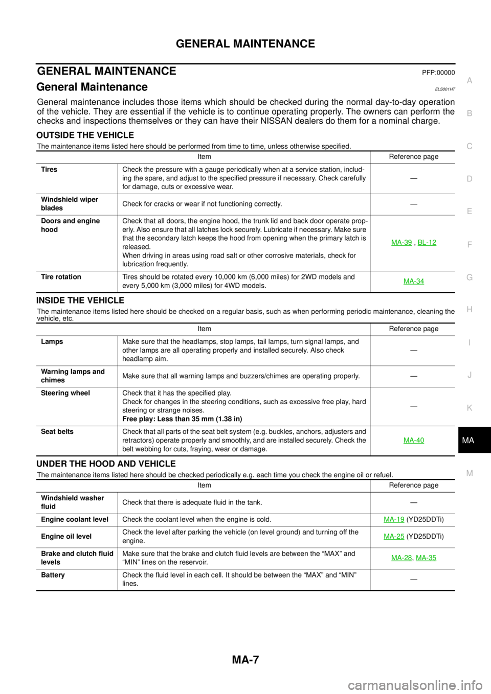
GENERAL MAINTENANCEPFP:00000
General MaintenanceELS001HT
General maintenance includes those items which should be checked during the normal day-to-day operation
of the vehicle. They are essential if the vehicle is to continue operating properly. The owners can perform the
checks and inspections themselves or they can have their NISSAN dealers do them for a nominal charge.
OUTSIDE THE VEHICLE
The maintenance items listed here should be performed from time to time, unless otherwise specified.
INSIDE THE VEHICLE
The maintenance items listed here should be checked on a regular basis, such as when performing periodic maintenance, cleaning the
vehicle, etc.
UNDER THE HOOD AND VEHICLE
The maintenance items listed here should be checked periodically e.g. each time you check the engine oil or refuel.Item Reference page
TiresCheck the pressure with a gauge periodically when at a service station, includ-
ing the spare, and adjust to the specified pressure if necessary. Check carefully
for damage, cuts or excessive wear.—
Windshield wiper
bladesCheck for cracks or wear if not functioning correctly. —
Doors and engine
hoodCheck that all doors, the engine hood, the trunk lid and back door operate prop-
erly. Also ensure that all latches lock securely. Lubricate if necessary. Make sure
that the secondary latch keeps the hood from opening when the primary latch is
released.
When driving in areas using road salt or other corrosive materials, check for
lubrication frequently.MA-39
,BL-12
Tire rotationTires should be rotated every 10,000 km (6,000 miles) for 2WD models and
every 5,000 km (3,000 miles) for 4WD models.MA-34
Item Reference page
LampsMake sure that the headlamps, stop lamps, tail lamps, turn signal lamps, and
other lamps are all operating properly and installed securely. Also check
headlamp aim.—
Warning lamps and
chimesMake sure that all warning lamps and buzzers/chimes are operating properly. —
Steering wheelCheck that it has the specified play.
Check for changes in the steering conditions, such as excessive free play, hard
steering or strange noises.
Free play: Less than 35 mm (1.38 in)—
Seat beltsCheck that all parts of the seat belt system (e.g. buckles, anchors, adjusters and
retractors) operate properly and smoothly, and are installed securely. Check the
belt webbing for cuts, fraying, wear or damage.MA-40
Item Reference page
Windshield washer
fluidCheck that there is adequate fluid in the tank. —
Engine coolant levelCheck the coolant level when the engine is cold.MA-19
(YD25DDTi)
Engine oil levelCheck the level after parking the vehicle (on level ground) and turning off the
engine.MA-25
(YD25DDTi)
Brake and clutch fluid
levelsMake sure that the brake and clutch fluid levels are between the “MAX” and
“MIN” lines on the reservoir.MA-28
,MA-35
BatteryCheck the fluid level in each cell. It should be between the “MAX” and “MIN”
lines.—