Page 1421 of 3171
OIL PAN AND OIL STRAINER
EM-39
C
D
E
F
G
H
I
J
K
L
MA
EM
CAUTION:
Install avoiding misalignment of O-ring.
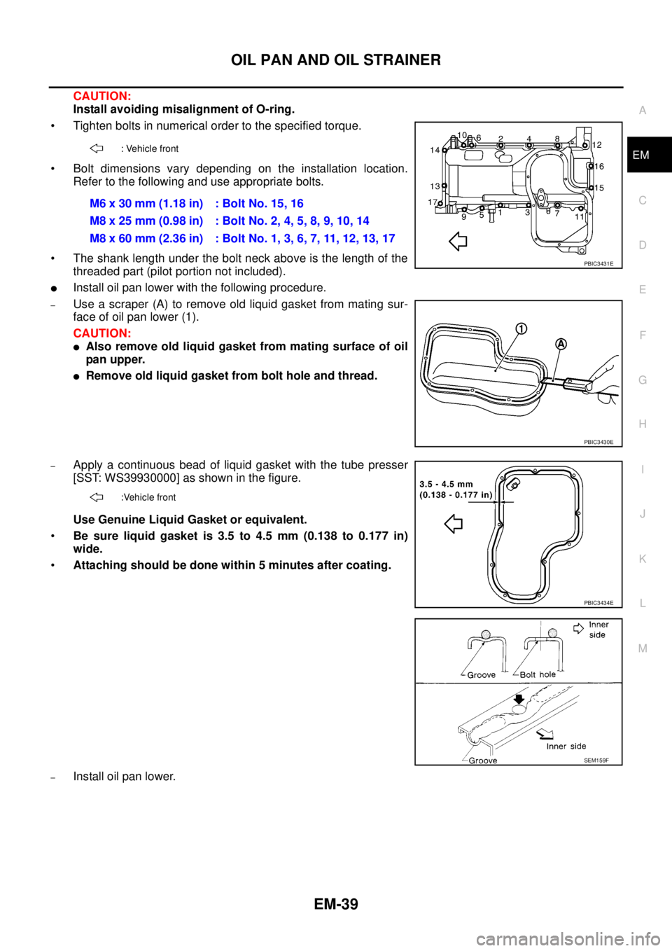
• Tighten bolts in numerical order to the specified torque.
• Bolt dimensions vary depending on the installation location.
Refer to the following and use appropriate bolts.
• The shank length under the bolt neck above is the length of the
threaded part (pilot portion not included).
lInstall oil pan lower with the following procedure.
–Use a scraper (A) to remove old liquid gasket from mating sur-
face of oil pan lower (1).
CAUTION:
lAlso remove old liquid gasket from mating surface of oil
pan upper.
lRemove old liquid gasket from bolt hole and thread.
–Apply a continuous bead of liquid gasket with the tube presser
[SST: WS39930000] as shown in the figure.
Use Genuine Liquid Gasket or equivalent.
•Be sure liquid gasket is 3.5 to 4.5 mm (0.138 to 0.177 in)
wide.
•Attaching should be done within 5 minutes after coating.
–Install oil pan lower.
: Vehicle front
M6x30mm(1.18in) :BoltNo.15,16
M8 x 25 mm (0.98 in) : Bolt No. 2, 4, 5, 8, 9, 10, 14
M8 x 60 mm (2.36 in) : Bolt No. 1, 3, 6, 7, 11, 12, 13, 17
PBIC3431E
PBIC3430E
:Vehicle front
PBIC3434E
SEM159F
Page 1422 of 3171
EM-40
OIL PAN AND OIL STRAINER
• Tighten bolts in numerical order to the specified torque.
NOTE:
Pour engine oil or start engine at least 30 minutes after oil pan is
installed.
INSPECTION AFTER INSTALLATION
1. Check engine oil level and add engine oil. Refer toLU-5, "ENGINE OIL".
2. Check for leakage of engine oil when engine is warmed.
3. Stop engine and wait for 10 minutes.
4. Check engine oil level again. Refer toLU-5, "
ENGINE OIL".
: Vehicle front
PBIC3425E
Page 1428 of 3171
EM-46
INJECTION TUBE AND FUEL INJECTOR
9. Following steps below, remove fuel injector.
a. Remove nozzle support.
b. Remove fuel injector. While rotating it to left and right, raise it to
remove.
CAUTION:
lHandle fuel injector carefully without giving any impact.
lDo not disassemble fuel injector.
c. If nozzle gasket remains in cylinder head, hook it with tip of a
flat-bladed screwdriver and pull it out.
d. Remove O-ring from fuel injector.
INSTALLATION
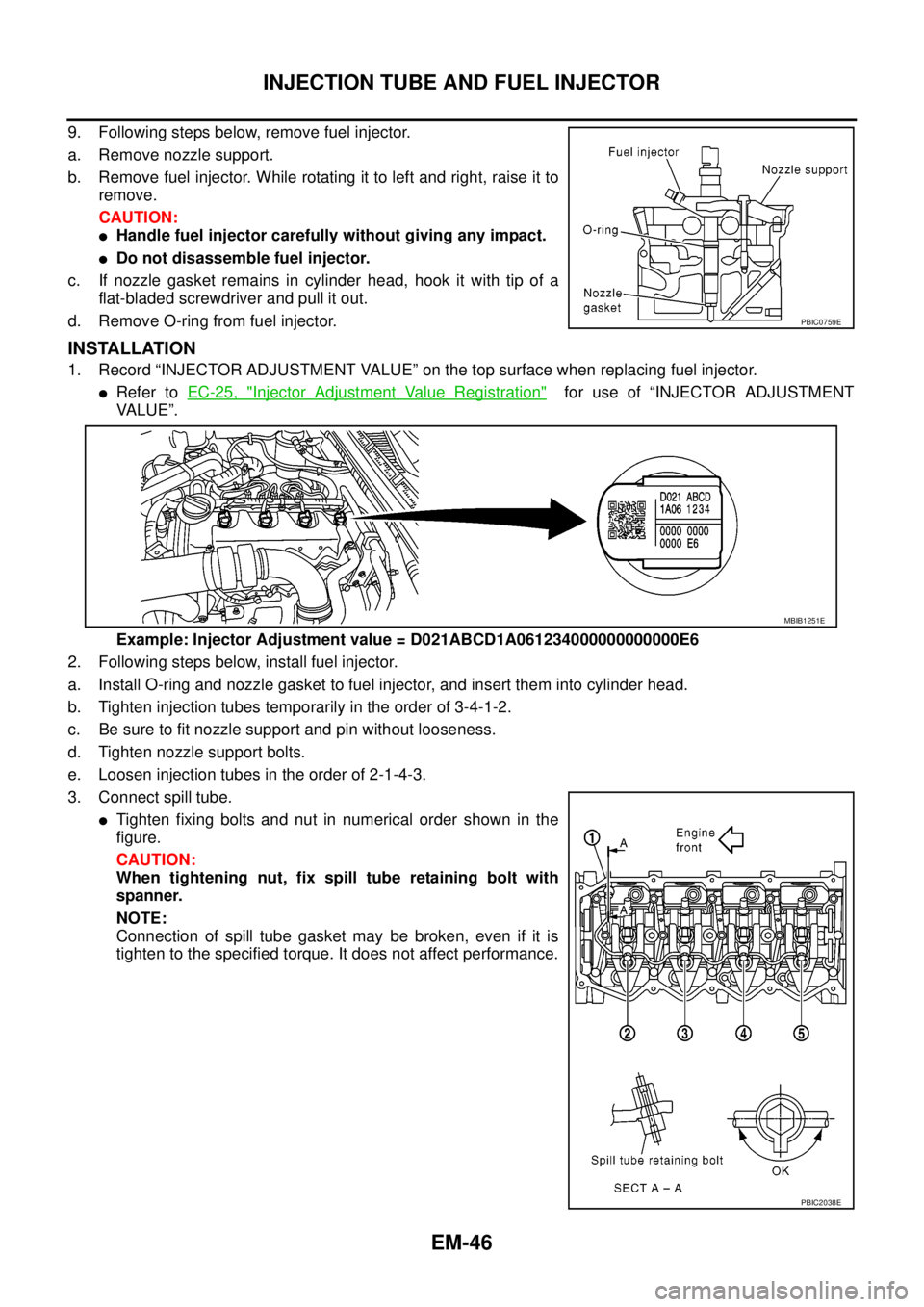
1. Record “INJECTOR ADJUSTMENT VALUE” on the top surface when replacing fuel injector.
lRefer toEC-25, "Injector Adjustment Value Registration"for use of “INJECTOR ADJUSTMENT
VALUE”.
Example: Injector Adjustment value = D021ABCD1A061234000000000000E6
2. Following steps below, install fuel injector.
a. Install O-ring and nozzle gasket to fuel injector, and insert them into cylinder head.
b. Tighten injection tubes temporarily in the order of 3-4-1-2.
c. Be sure to fit nozzle support and pin without looseness.
d. Tighten nozzle support bolts.
e. Loosen injection tubes in the order of 2-1-4-3.
3. Connect spill tube.
lTighten fixing bolts and nut in numerical order shown in the
figure.
CAUTION:
When tightening nut, fix spill tube retaining bolt with
spanner.
NOTE:
Connection of spill tube gasket may be broken, even if it is
tighten to the specified torque. It does not affect performance.
PBIC0759E
MBIB1251E
PBIC2038E
Page 1439 of 3171
ROCKER COVER
EM-57
C
D
E
F
G
H
I
J
K
L
MA
EM
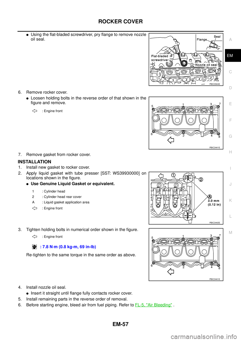
lUsing the flat-bladed screwdriver, pry flange to remove nozzle
oil seal.
6. Remove rocker cover.
lLoosen holding bolts in the reverse order of that shown in the
figure and remove.
7. Remove gasket from rocker cover.
INSTALLATION
1. Install new gasket to rocker cover.
2. Apply liquid gasket with tube presser [SST: WS39930000] on
locations shown in the figure.
lUse Genuine Liquid Gasket or equivalent.
3. Tighten holding bolts in numerical order shown in the figure.
Re-tighten to the same torque in the same order as above.
4. Install nozzle oil seal.
lInsert it straight until flange fully contacts rocker cover.
5. Install remaining parts in the reverse order of removal.
6. Before starting engine, bleed air from fuel piping. Refer toFL-5, "
Air Bleeding".
PBIC0944E
: Engine front
PBIC3441E
1 : Cylinder head
2 : Cylinder head rear cover
A : Liquid gasket application area
: Engine front
PBIC3442E
: Engine front
: 7.8 N·m (0.8 kg-m, 69 in-lb)
PBIC3441E
Page 1443 of 3171
CAMSHAFT
EM-61
C
D
E
F
G
H
I
J
K
L
MA
EM
Camshaft Runout
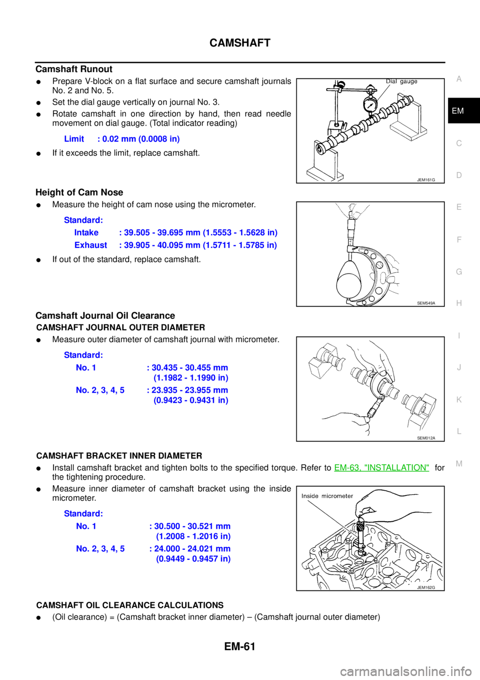
lPrepare V-block on a flat surface and secure camshaft journals
No. 2 and No. 5.
lSet the dial gauge vertically on journal No. 3.
lRotate camshaft in one direction by hand, then read needle
movement on dial gauge. (Total indicator reading)
lIf it exceeds the limit, replace camshaft.
Height of Cam Nose
lMeasure the height of cam nose using the micrometer.
lIf out of the standard, replace camshaft.
Camshaft Journal Oil Clearance
CAMSHAFT JOURNAL OUTER DIAMETER
lMeasure outer diameter of camshaft journal with micrometer.
CAMSHAFT BRACKET INNER DIAMETER
lInstall camshaft bracket and tighten bolts to the specified torque. Refer toEM-63, "INSTALLATION"for
the tightening procedure.
lMeasure inner diameter of camshaft bracket using the inside
micrometer.
CAMSHAFT OIL CLEARANCE CALCULATIONS
l(Oil clearance) = (Camshaft bracket inner diameter) – (Camshaft journal outer diameter)Limit : 0.02 mm (0.0008 in)
JEM161G
Standard:
Intake : 39.505 - 39.695 mm (1.5553 - 1.5628 in)
Exhaust : 39.905 - 40.095 mm (1.5711 - 1.5785 in)
SEM549A
Standard:
No. 1 : 30.435 - 30.455 mm
(1.1982 - 1.1990 in)
No.2,3,4,5 :23.935-23.955mm
(0.9423 - 0.9431 in)
SEM012A
Standard:
No. 1 : 30.500 - 30.521 mm
(1.2008 - 1.2016 in)
No.2,3,4,5 :24.000-24.021mm
(0.9449 - 0.9457 in)
JEM162G
Page 1463 of 3171
![NISSAN NAVARA 2005 Repair Workshop Manual PRIMARY TIMING CHAIN
EM-81
C
D
E
F
G
H
I
J
K
L
MA
EM
c. Using the pulley puller [SST], remove crankshaft pulley.
lUse two M6 bolts with approx. 60 mm (2.36 in) shank length
for securing crankshaft pul NISSAN NAVARA 2005 Repair Workshop Manual PRIMARY TIMING CHAIN
EM-81
C
D
E
F
G
H
I
J
K
L
MA
EM
c. Using the pulley puller [SST], remove crankshaft pulley.
lUse two M6 bolts with approx. 60 mm (2.36 in) shank length
for securing crankshaft pul](/manual-img/5/57362/w960_57362-1462.png)
PRIMARY TIMING CHAIN
EM-81
C
D
E
F
G
H
I
J
K
L
MA
EM
c. Using the pulley puller [SST], remove crankshaft pulley.
lUse two M6 bolts with approx. 60 mm (2.36 in) shank length
for securing crankshaft pulley.
9. Remove oil pump housing.
lLoosen bolts in reverse order of that shown in the figure and
remove them.
lU s e t h e s e a l c u t t e r [ S S T: K V 1 0 1111 0 0 ] e t c . f o r r e m o v a l .
10. Remove crankshaft gear.
lRemove crankshaft gear (1) with the following procedure
(4WD models).
a. Make sure that No.1 piston is TDC on its compression stroke.
b. Turn the idler sub gear (3) counterclockwise with snap ring plier
(B) or suitable tool for aligning idler sub gear (3) and idler main
gear (2).
lIf idler gear rotates, hold the flat faces on balancer drive shaft
front end (4).
c. Install internal mechanism securing bolt and plate (Service part:
13012 EB30A and 13013 EB30A) (A) and tighten to the speci-
fied torque.
CAUTION:
lDo not loosen idler gear mounting bolt (5).
lOnly use the genuine internal mechanism securing bolt
and plate (A), or the idler gear (2) and (3) will be damaged.
lDo not remove internal mechanism securing bolt and
plate (A) from idler gear (2) and (3) until crankshaft gear
(1) and all of the parts in connection have been installed.
lIf internal mechanism securing bolt and plate (A) is not
installed, internal mechanism of idler gear (2) and (3) will
disengage after crankshaft gear (1) is removed. This will prohibit the balancer unit from being
reusable.
d. Apply mating marks (C) to crankshaft gear (1) and idler sub gear (3).
e. Remove crankshaft gear (1).
11. Remove front oil seal from oil pump housing.
lPunch out the seal off from the back surface of the oil pump housing using a flat-bladed screwdriver.
CAUTION:
Be careful not to damage oil pump housing.
JEM132G
PBIC3470E
: 4.0 N·m (0.41 kg-m, 35 in-lb)
PBIC3471E
Page 1498 of 3171
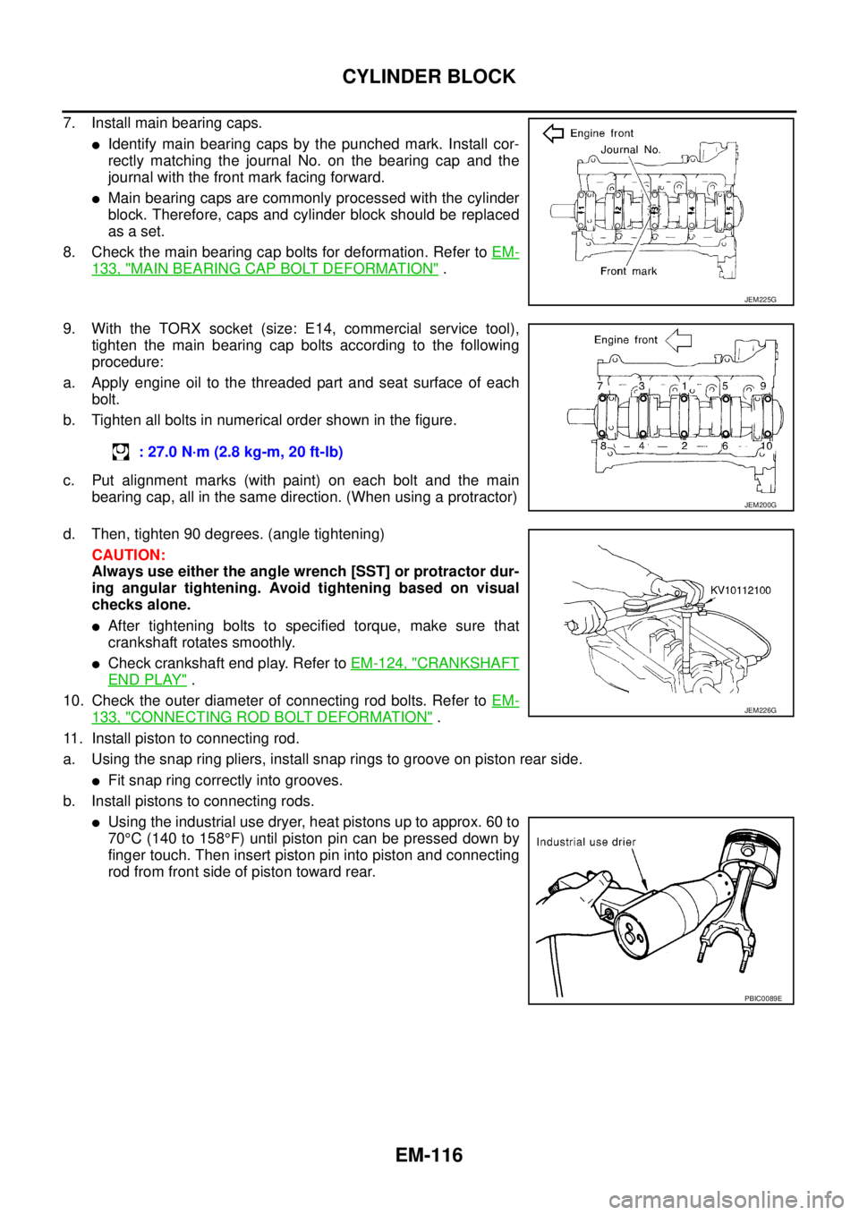
EM-116
CYLINDER BLOCK
7. Install main bearing caps.
lIdentify main bearing caps by the punched mark. Install cor-
rectly matching the journal No. on the bearing cap and the
journal with the front mark facing forward.
lMain bearing caps are commonly processed with the cylinder
block. Therefore, caps and cylinder block should be replaced
as a set.
8. Check the main bearing cap bolts for deformation. Refer toEM-
133, "MAIN BEARING CAP BOLT DEFORMATION".
9. With the TORX socket (size: E14, commercial service tool),
tighten the main bearing cap bolts according to the following
procedure:
a. Apply engine oil to the threaded part and seat surface of each
bolt.
b. Tighten all bolts in numerical order shown in the figure.
c. Put alignment marks (with paint) on each bolt and the main
bearing cap, all in the same direction. (When using a protractor)
d. Then, tighten 90 degrees. (angle tightening)
CAUTION:
Always use either the angle wrench [SST] or protractor dur-
ing angular tightening. Avoid tightening based on visual
checks alone.
lAfter tightening bolts to specified torque, make sure that
crankshaft rotates smoothly.
lCheck crankshaft end play. Refer toEM-124, "CRANKSHAFT
END PLAY".
10. Check the outer diameter of connecting rod bolts. Refer toEM-
133, "CONNECTING ROD BOLT DEFORMATION".
11. Install piston to connecting rod.
a. Using the snap ring pliers, install snap rings to groove on piston rear side.
lFit snap ring correctly into grooves.
b. Install pistons to connecting rods.
lUsing the industrial use dryer, heat pistons up to approx. 60 to
70°C(140to158°F) until piston pin can be pressed down by
finger touch. Then insert piston pin into piston and connecting
rod from front side of piston toward rear.
JEM225G
: 27.0 N·m (2.8 kg-m, 20 ft-lb)
JEM200G
JEM226G
PBIC0089E
Page 1509 of 3171
CYLINDER BLOCK
EM-127
C
D
E
F
G
H
I
J
K
L
MA
EM
CONNECTING ROD BEND AND TORSION
lUse connecting rod aligner to check bend and torsion.
lIf it exceeds the limit, replace connecting rod assembly.
CONNECTING ROD BIG END INNER DIAMETER
lInstall connecting rod caps without connecting rod bearings and
tighten connecting rod nuts to the specified torque. Refer toEM-
11 4 , "ASSEMBLY".
lUsing inside micrometer, measure connecting rod big end inner
diameter.
lIf out of the standard, replace connecting rod.
CONNECTING ROD BUSHING OIL CLEARANCE
Connecting Rod Bushing Inner Diameter
Use inside micrometer to measure bushing inner diameter.Bend limit : 0.12 mm (0.0047 in)/100 mm (3.94 in)
Torsion limit : 0.12 mm (0.0047 in)/100 mm (3.94 in)
PBIC2077E
Standard : 55.000 - 55.013 mm (2.1654 - 2.1659 in)
PBIC1641E
Standard : 28.026 - 28.038 mm (1.1034 - 1.1039 in)
PBIC0120E