2005 NISSAN NAVARA torque
[x] Cancel search: torquePage 330 of 3171
AT-322
ASSEMBLY
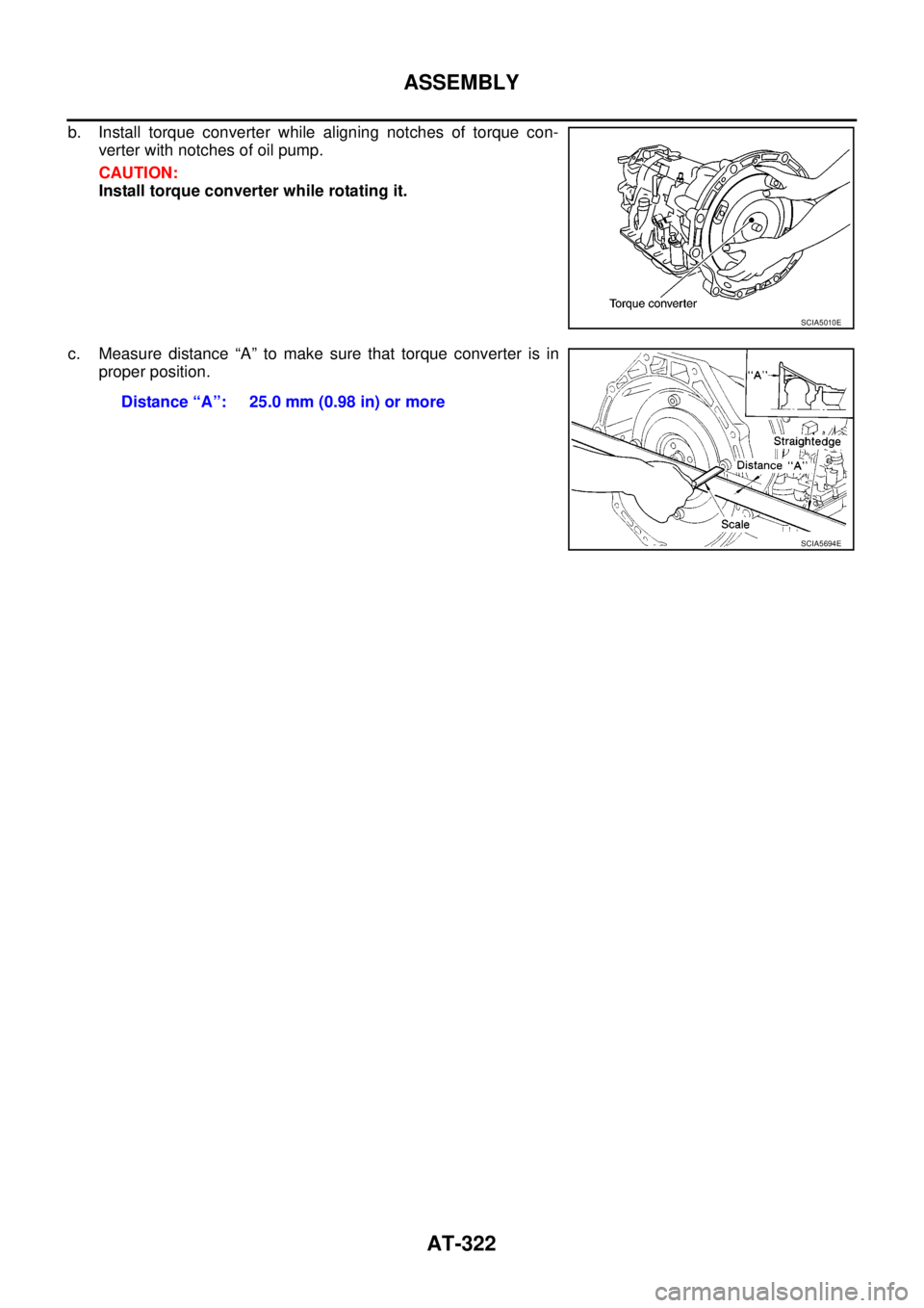
b. Install torque converter while aligning notches of torque con-
verter with notches of oil pump.
CAUTION:
Install torque converter while rotating it.
c. Measure distance “A” to make sure that torque converter is in
proper position.
SCIA5010E
Distance “A”: 25.0 mm (0.98 in) or more
SCIA5694E
Page 331 of 3171
SERVICE DATA AND SPECIFICATIONS (SDS)
AT-323
D
E
F
G
H
I
J
K
L
MA
B
AT
SERVICE DATA AND SPECIFICATIONS (SDS)PFP:00030
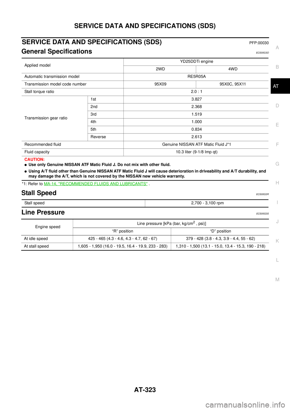
General SpecificationsECS00G3O
*1: Refer toMA-14, "RECOMMENDED FLUIDS AND LUBRICANTS".
Stall SpeedECS00G3R
Line PressureECS00G3S
Applied modelYD25DDTi engine
2WD 4WD
Automatic transmission model RE5R05A
Transmission model code number 95X09 95X0C, 95X11
Stall torque ratio2.0 : 1
Transmission gear ratio1st 3.827
2nd 2.368
3rd 1.519
4th 1.000
5th 0.834
Reverse 2.613
Recommended fluid Genuine NISSAN ATF Matic Fluid J*1
Fluid capacity 10.3 liter (9-1/8 Imp qt)
CAUTION:
lUse only Genuine NISSAN ATF Matic Fluid J. Do not mix with other fluid.
lUsing A/T fluid other than Genuine NISSAN ATF Matic Fluid J will cause deterioration in driveability and A/T durability, and
may damage the A/T, which is not covered by the NISSAN new vehicle warranty.
Stall speed2,700 - 3,100 rpm
Engine speedLine pressure [kPa (bar, kg/cm2,psi)]
“R” position “D” position
At idle speed 425 - 465 (4.3 - 4.6, 4.3 - 4.7, 62 - 67) 379 - 428 (3.8 - 4.3, 3.9 - 4.4, 55 - 62)
At stall speed 1,605 - 1,950 (16.0 - 19.5, 16.4 - 19.9, 233 - 283) 1,310 - 1,500 (13.1 - 15.0, 13.4 - 15.3, 190 - 218)
Page 339 of 3171
PRECAUTIONS
ATC-5
C
D
E
F
G
H
I
K
L
MA
B
AT C
lIf the vehicle is within the warranty period, the air conditioner warranty is void. Please contact NISSAN
Customer Affairs for further assistance.
General Refrigerant PrecautionsEJS006AN
WARNING:
lDo not release refrigerant into the air. Use approved recovery/recycling equipment to capture the
refrigerant every time an air conditioning system is discharged.
lAlways wear eye and hand protection (goggles and gloves) when working with any refrigerant or
air conditioning system.
lDo not store or heat refrigerant containers above 52°C.
lDo not heat a refrigerant container with an open flame; if container warming is required, place the
bottom of the container in a warm pail of water.
lDo not intentionally drop, puncture, or incinerate refrigerant containers.
lKeep refrigerant away from open flames: poisonous gas will be produced if refrigerant burns.
lRefrigerant will displace oxygen, therefore be certain to work in well ventilated areas to prevent
suffocation.
lDo not pressure test or leak test HFC-134a (R-134a) service equipment and/or vehicle air condi-
tioning systems with compressed air during repair. Some mixtures of air and HFC-134a (R-134a)
have been shown to be combustible at elevated pressures. These mixtures, if ignited, may cause
injury or property damage. Additional health and safety information may be obtained from refriger-
ant manufacturers.
Precautions for Refrigerant ConnectionEJS006AO
A new type refrigerant connection has been introduced to all refrigerant lines except the following locations.
lExpansion valve to cooling unit
lEvaporator pipes to evaporator (inside cooling unit)
lRefrigerant pressure sensor
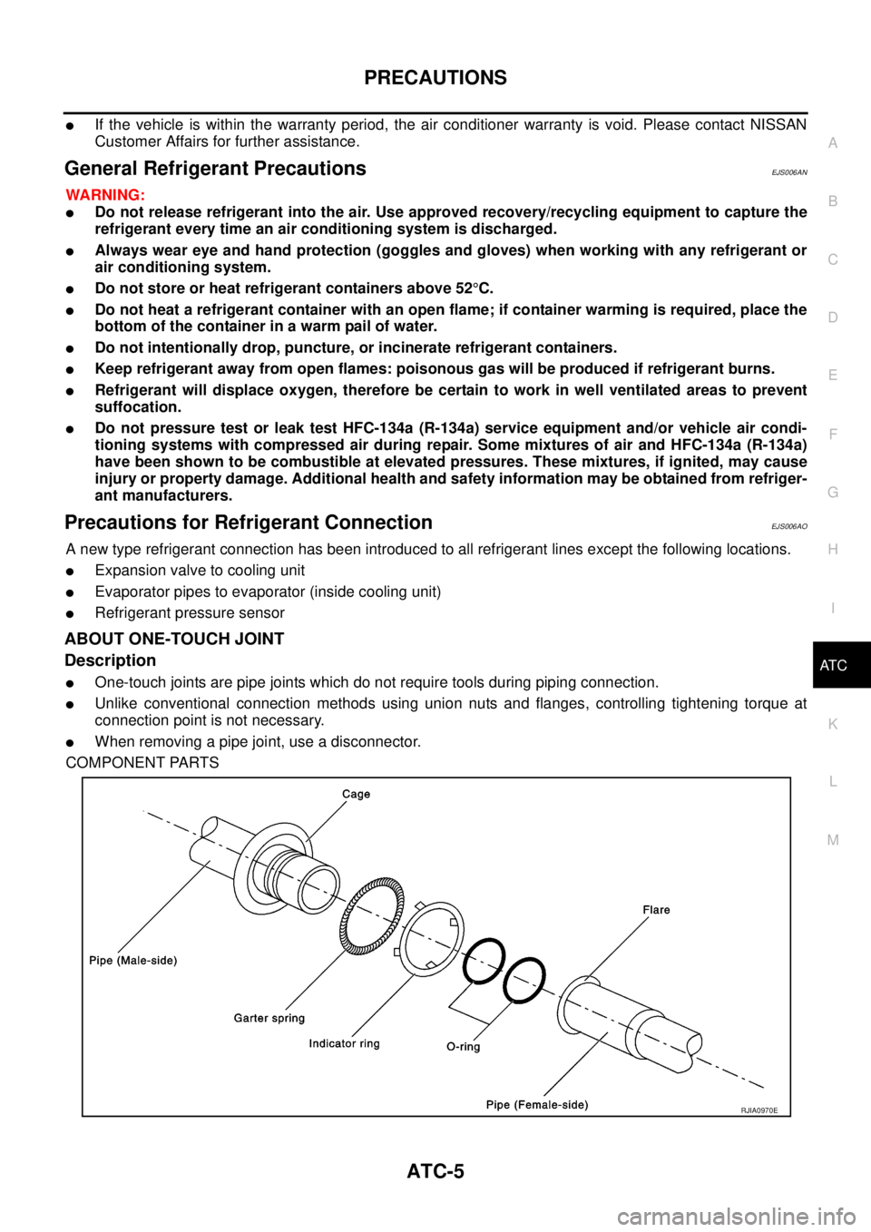
ABOUT ONE-TOUCH JOINT
Description
lOne-touch joints are pipe joints which do not require tools during piping connection.
lUnlike conventional connection methods using union nuts and flanges, controlling tightening torque at
connection point is not necessary.
lWhen removing a pipe joint, use a disconnector.
COMPONENT PARTS
RJIA0970E
Page 345 of 3171
PRECAUTIONS
ATC-11
C
D
E
F
G
H
I
K
L
MA
B
AT C
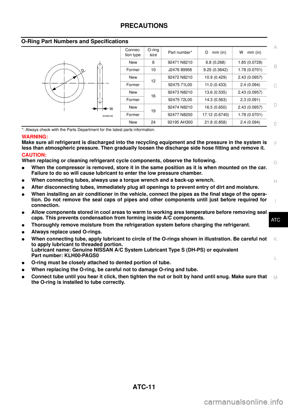
O-Ring Part Numbers and Specifications
*: Always check with the Parts Department for the latest parts information.
WARNING:
Make sure all refrigerant is discharged into the recycling equipment and the pressure in the system is
less than atmospheric pressure. Then gradually loosen the discharge side hose fitting and remove it.
CAUTION:
When replacing or cleaning refrigerant cycle components, observe the following.
lWhen the compressor is removed, store it in the same position as it is when mounted on the car.
Failure to do so will cause lubricant to enter the low pressure chamber.
lWhen connecting tubes, always use a torque wrench and a back-up wrench.
lAfter disconnecting tubes, immediately plug all openings to prevent entry of dirt and moisture.
lWhen installing an air conditioner in the vehicle, connect the pipes as the final stage of the opera-
tion. Do not remove the seal caps of pipes and other components until just before required for
connection.
lAllow components stored in cool areas to warm to working area temperature before removing seal
caps. This prevents condensation from forming inside A/C components.
lThoroughly remove moisture from the refrigeration system before charging the refrigerant.
lAlways replace used O-rings.
lWhen connecting tube, apply lubricant to circle of the O-rings shown in illustration. Be careful not
to apply lubricant to threaded portion.
Lubricant name: Genuine NISSAN A/C System Lubricant Type S (DH-PS) or equivalent
Part number: KLH00-PAGS0
lO-ring must be closely attached to dented portion of tube.
lWhen replacing the O-ring, be careful not to damage O-ring and tube.
lConnect tube until you hear it click, then tighten the nut or bolt by hand until snug. Make sure that
the O-ring is installed to tube correctly.
Connec-
tion typeO-ring
sizePart number* D mm (in) W mm (in)
New 8 92471 N8210 6.8 (0.268) 1.85 (0.0728)
Former 10 J2476 89956 9.25 (0.3642) 1.78 (0.0701)
New
1292472 N8210 10.9 (0.429) 2.43 (0.0957)
Former 92475 71L00 11.0 (0.433) 2.4 (0.094)
New
1692473 N8210 13.6 (0.535) 2.43 (0.0957)
Former 92475 72L00 14.3 (0.563) 2.3 (0.091)
New
1992474 N8210 16.5 (0.650) 2.43 (0.0957)
Former 92477 N8200 17.12 (0.6740) 1.78 (0.0701)
New 24 92195 AH300 21.8 (0.858) 2.4 (0.094)
SHA814E
Page 346 of 3171
ATC-12
PRECAUTIONS
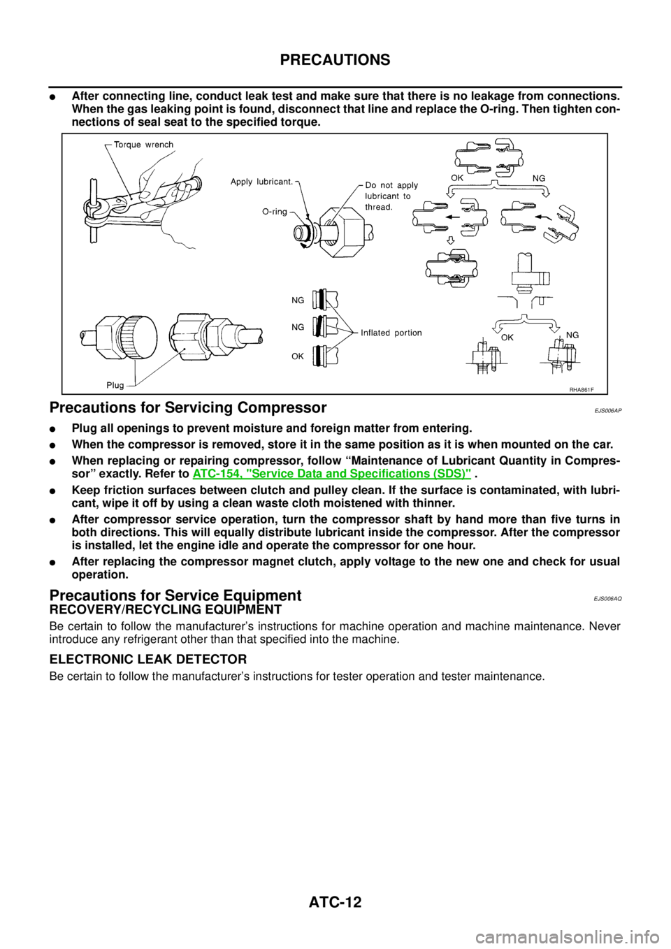
lAfter connecting line, conduct leak test and make sure that there is no leakage from connections.
When the gas leaking point is found, disconnect that line and replace the O-ring. Then tighten con-
nections of seal seat to the specified torque.
Precautions for Servicing CompressorEJS006AP
lPlug all openings to prevent moisture and foreign matter from entering.
lWhen the compressor is removed, store it in the same position as it is when mounted on the car.
lWhen replacing or repairing compressor, follow “Maintenance of Lubricant Quantity in Compres-
sor” exactly. Refer toATC-154, "
Service Data and Specifications (SDS)".
lKeep friction surfaces between clutch and pulley clean. If the surface is contaminated, with lubri-
cant, wipe it off by using a clean waste cloth moistened with thinner.
lAfter compressor service operation, turn the compressor shaft by hand more than five turns in
both directions. This will equally distribute lubricant inside the compressor. After the compressor
is installed, let the engine idle and operate the compressor for one hour.
lAfter replacing the compressor magnet clutch, apply voltage to the new one and check for usual
operation.
Precautions for Service EquipmentEJS006AQ
RECOVERY/RECYCLING EQUIPMENT
Be certain to follow the manufacturer’s instructions for machine operation and machine maintenance. Never
introduce any refrigerant other than that specified into the machine.
ELECTRONIC LEAK DETECTOR
Be certain to follow the manufacturer’s instructions for tester operation and tester maintenance.
RHA861F
Page 480 of 3171
ATC-146
REFRIGERANT LINES
BREAK-IN OPERATION
When replacing compressor clutch assembly, always conduct the break-in operation. This is done by engag-
ing and disengaging the clutch about 30 times. Break-in operation raises the level of transmitted torque.
Removal and Installation for High-pressure Flexible A/C HoseEJS006CP
REMOVAL
1. Remove the front left wheel and tire assembly. Refer toWT-5, "Rotation".
2. Remove the front left mud guard.
3. Remove the front left splash shield.
4. Discharge the refrigerant. Refer toATC-138, "
HFC-134a (R-134a) Service Procedure".
5. Remove the high-pressure flexible A/C hose. Refer toATC-140, "
Components".
CAUTION:
Cap or wrap the joint of the pipe with suitable material such as vinyl tape to avoid the entry of air.
INSTALLATION
Installation is in the reverse order of removal.
Refer toATC-140, "
Components".
CAUTION:
lReplace the O-ring of the high-pressure flexible A/C hose with a new one, then apply compressor
oil to it for installation.
lAfter charging refrigerant, check for leaks.
Removal and Installation for High-pressure A/C PipeEJS006CQ
REMOVAL
1. Remove the front right wheel and tire assembly. Refer toWT-5, "Rotation".
2. Remove the front right mud guard.
3. Remove the front right splash shield.
4. Discharge the refrigerant. Refer toATC-138, "
HFC-134a (R-134a) Service Procedure".
5. Remove the low pressure A/C pipe. Refer toATC-147, "
Removal and Installation for Low-pressure A/C
Pipe".
6. Remove the high-pressure A/C pipe. Refer toATC-146, "
Removal and Installation for High-pressure A/C
Pipe".
CAUTION:
Cap or wrap the joint of the pipe with suitable material such as vinyl tape to avoid the entry of air.
INSTALLATION
Installation is in the reverse order of removal.
Refer toATC-140, "
Components".
CAUTION:
lReplace the O-ring of the high-pressure A/C pipe with a new one, then apply compressor oil to it
for installation.
lAfter charging refrigerant, check for leaks.
Removal and Installation for Low-pressure Flexible A/C HoseEJS006CR
REMOVAL
1. Remove the front right wheel and tire assembly. Refer toWT-5, "Rotation".
2. Remove the front right mud guard.
3. Remove the front right splash shield.
4. Discharge the refrigerant. Refer toATC-138, "
HFC-134a (R-134a) Service Procedure".
CAUTION:
Cap or wrap the joint of the pipe with suitable material such as vinyl tape to avoid the entry of air.
5. Remove the low-pressure flexible A/C hose. Refer toATC-140, "
Components".
INSTALLATION
Installation is in the reverse order of removal.
Refer toATC-140, "
Components".
Page 597 of 3171

HOOD
BL-13
C
D
E
F
G
H
J
K
L
MA
B
BL
LONGITUDINAL AND LATERAL CLEARANCE ADJUSTMENT
1. Remove the hood lock, loosen the hood hinge nuts and close the hood.
2. Adjust the lateral and longitudinal clearance, and open the hood to tighten the mounting bolts to the spec-
ified torque.
3. Install the hood lock temporarily, and align the hood striker and lock so that the centers of striker and lock
become vertical viewed from the front, by moving the hood lock laterally.
4. Tighten hood lock mounting bolts to the specified torque.
FRONT END HEIGHT ADJUSTMENT
1. Remove the hood lock and adjust the height by rotating the bumper rubber until the hood becomes 1 to1.5
mm (0.04 to 0.059 in) lower than the fender.
2. Temporarily tighten the hood lock, and position it by engaging it with the hood striker. Check the lock and
striker for looseness, and tighten the hood lock mounting bolts to the specified torque.
CAUTION:
Adjust right/left clearance between hood and each part to the following specification.
SURFACE HEIGHT ADJUSTMENT
1. Remove the hood lock, and adjust the surface height difference of hood, fender and headlamp according
to the fitting standard dimension, by rotating RH and LH bumper rubbers.
2. Install hood lock temporarily, and move hood lock laterally until the centers of striker and lock become ver-
tical when viewed from the front.
3. Check that the hood lock secondary latch is properly engaged with the secondary striker with hood's own
weight.
4. Check that the hood lock primary latch is securely engaged with the hood striker with hood's own weight
by dropping hood from approx. 200 mm (7.87) height.
CAUTION:
Do not drop hood from a height of 300 mm (11.81 in) or more.
5. Move hood lockup and down until striker smoothly engages the lock when the hood is closed.
6. When pulling the hood opener lever gently, make sure that front end of the hood rises by approximately 20
mm (0.79) and that hood striker and hood lock primary latch is disengaged. Also make sure that hood
opener returns to the original position.
7. After adjustment, tighten lock bolts to the specified torque.
CAUTION:
lAfter installing, apply touch-up paint (the body color) onto the head of the hinge mounting nuts.
lAdjust evenness between hood and each part to the following specification.
Portion Clearance
Hood - Front grille A - A (a) 3.7 - 8.3 mm (0.146 - 0.327 in)
Hood - Front fender B - B (c) 3.6 - 5.6 mm (0.142 - 0.220 in)
Hood - Headlamp C - C (e) 6.0 - 8.0 mm (0.236 - 0.315 in)
Portion R / L difference
Hood - Front grille A - A (a) Less than 2.2 mm (0.087 in)
Hood - Front fender B - B (c) Less than 1.0 mm (0.039 In)
Portion Surface height
Hood - Front grille A - A (b) -1.7 - 3.1 mm (-0.067 - 0.122 in)
Hood - Front fender B - B (d) -1.0 - 1.0 mm (-0.039 - 0.039 in)
Hood - Headlamp C - C (f) -1.3 - 2.7 mm (-0.051 - 0.106 in)
Page 789 of 3171
PRECAUTIONS
BR-3
C
D
E
G
H
I
J
K
L
MA
B
BR
PRECAUTIONSPFP:00001
Precautions for Supplemental Restraint System (SRS) “AIR BAG” and “SEAT
BELT PRE-TENSIONER”
EFS006DL
The Supplemental Restraint System such as “AIR BAG” and “SEAT BELT PRE-TENSIONER”, used along
with a front seat belt, helps to reduce the risk or severity of injury to the driver and front passenger for certain
types of collision. Information necessary to service the system safely is included in the SRS and SB section of
this Service Manual.
WARNING:
lTo avoid rendering the SRS inoperative, which could increase the risk of personal injury or death
in the event of a collision which would result in air bag inflation, all maintenance must be per-
formed by an authorized NISSAN/INFINITI dealer.
lImproper maintenance, including incorrect removal and installation of the SRS, can lead to per-
sonal injury caused by unintentional activation of the system. For removal of Spiral Cable and Air
Bag Module, see the SRS section.
lDo not use electrical test equipment on any circuit related to the SRS unless instructed to in this
Service Manual. SRS wiring harnesses can be identified by yellow and/or orange harnesses or
harness connectors.
Precautions for Brake SystemEFS005SD
lClean dust on front brake and rear brake with a vacuum dust collector. Do not blow with compressed air.
lRecommended fluid is brake fluid “DOT 3” or “DOT 4”.
lNever reuse drained brake fluid.
lBe careful not to splash brake fluid on painted areas; it may cause paint damage. If brake fluid is splashed
on painted areas, wash it away with water immediately.
lTo clean or wash all parts of master cylinder, disc brake caliper, wheel cylinder, use new brake fluid.
lNever use mineral oils such as gasoline or kerosene. They will ruin rubber parts of the hydraulic system.
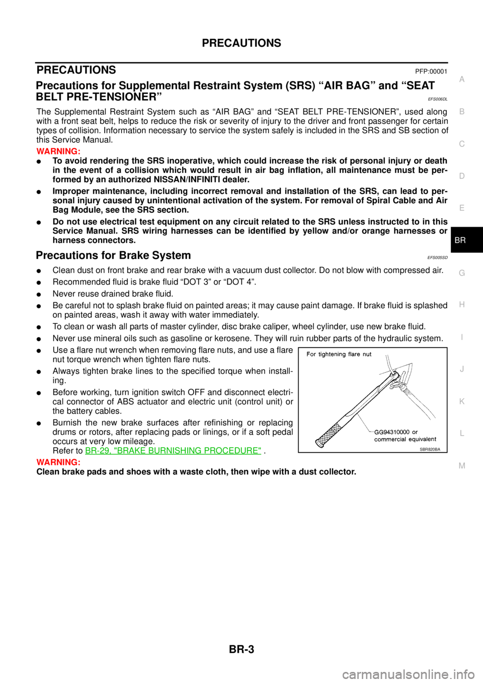
lUse a flare nut wrench when removing flare nuts, and use a flare
nut torque wrench when tighten flare nuts.
lAlways tighten brake lines to the specified torque when install-
ing.
lBefore working, turn ignition switch OFF and disconnect electri-
cal connector of ABS actuator and electric unit (control unit) or
the battery cables.
lBurnish the new brake surfaces after refinishing or replacing
drums or rotors, after replacing pads or linings, or if a soft pedal
occurs at very low mileage.
Refer toBR-29, "
BRAKE BURNISHING PROCEDURE".
WARNING:
Clean brake pads and shoes with a waste cloth, then wipe with a dust collector.SBR820BA