Page 2159 of 4770
N20557
TMMK made:
TMC made:1
2
N20558
TMMK made:
TMC made:1 2
± BODY ELECTRICALPOWER WINDOW CONTROL SYSTEM
BE±65
2285 Author�: Date�:
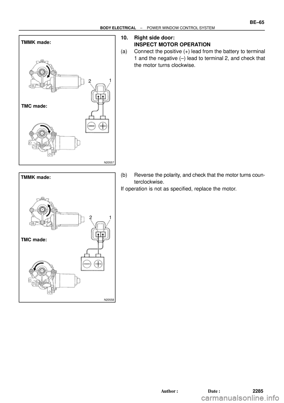
10. Right side door:
INSPECT MOTOR OPERATION
(a) Connect the positive (+) lead from the battery to terminal
1 and the negative (±) lead to terminal 2, and check that
the motor turns clockwise.
(b) Reverse the polarity, and check that the motor turns coun-
terclockwise.
If operation is not as specified, replace the motor.
Page 2169 of 4770
N21182
Webasto type:
DENSO type:21
1
2
Webasto type:
N21183
DENSO type:21
1
2
N21644
Within
10 to 60
seconds
± BODY ELECTRICALSLIDING ROOF SYSTEM
BE±75
2295 Author�: Date�:
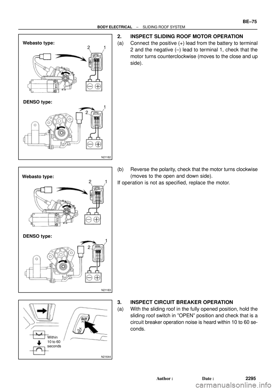
2. INSPECT SLIDING ROOF MOTOR OPERATION
(a) Connect the positive (+) lead from the battery to terminal
2 and the negative (±) lead to terminal 1, check that the
motor turns counterclockwise (moves to the close and up
side).
(b) Reverse the polarity, check that the motor turns clockwise
(moves to the open and down side).
If operation is not as specified, replace the motor.
3. INSPECT CIRCUIT BREAKER OPERATION
(a) With the sliding roof in the fully opened position, hold the
sliding roof switch in ºOPENº position and check that is a
circuit breaker operation noise is heard within 10 to 60 se-
conds.
Page 2173 of 4770

(b)
1 21
2
± BODY ELECTRICALPOWER SEAT CONTROL SYSTEM
BE±79
2299 Author�: Date�:
3. TMC made:
INSPE")
I01932
Lifter Up
Down
Slide FrontRear Reclining
Forward
Rear
1 2 3 4 5
6 7 8 9 10 11 12
N21865
(a)
(b)
1 21
2
± BODY ELECTRICALPOWER SEAT CONTROL SYSTEM
BE±79
2299 Author�: Date�:
3. TMC made:
INSPECT PASSENGER'S SEAT CONTINUITY
(a) Inspect the slide switch.
Switch positionTester connectionSpecified condition
FRONT4 ± 6, 8 ± 11Continuity
OFF4 ± 6, 6 ± 8Continuity
BACK6 ± 8, 4 ± 11Continuity
(b) Inspect the lifter switch.
Switch positionTester connectionSpecified condition
UP2 ± 6, 3 ± 11Continuity
OFF3 ± 6, 2 ± 6Continuity
DOWN3 ± 6, 2 ± 11Continuity
(c) Inspect the reclining switch.
Switch positionTester connectionSpecified condition
FORWARD5 ± 6, 1 ± 11Continuity
OFF1 ± 6, 5 ± 6Continuity
REAR1 ± 6, 5 ± 11Continuity
If continuity is not as specified, replace the switch.
4. TMMK made:
INSPECT PASSENGER'S SEAT CONTINUITY
(a) Inspect the slide switch.
Switch positionTester connectionSpecified condition
FRONT2 ± 11, 4 ± 7Continuity
OFF4 ± 11, 4 ± 7Continuity
BACK2 ± 7, 4 ± 11Continuity
(b) Inspect the lifter switch.
Switch positionTester connectionSpecified condition
UP2 ± 8, 4 ± 5Continuity
OFF4 ± 5, 4 ± 8Continuity
DOWN2 ± 5, 4 ± 8Continuity
(c) Inspect the reclining switch.
Switch positionTester connectionSpecified condition
FORWARD2 ± 12, 4 ± 6Continuity
OFF4 ± 12, 4 ± 6Continuity
REAR2 ± 6, 4 ± 12Continuity
If continuity is not as specified, replace the switch.
5. INSPECT SLIDE MOTOR OPERATION
(a) Connect the positive (+) lead from the battery to terminal
2 and the negative (±) lead to terminal 1, check that the
motor turns counterclockwise.
(b) Reverse the polarity, check that the motor turns clock-
wise.
If operation is not as specified, replace the seat adjuster.
Page 2174 of 4770

(b)
1 21
2
N21868
1 2
N21869
1 2 BE±80
± BODY ELECTRICALPOWER SEAT CONTROL SYSTEM
2300 Author�: Date�:
6. INSPECT SLIDE MOTOR PTC THERMISTOR OPERA-
TION
(a) Connect")
N21866
1 2
N21867
1 2
N21865
(a)
(b)
1 21
2
N21868
1 2
N21869
1 2 BE±80
± BODY ELECTRICALPOWER SEAT CONTROL SYSTEM
2300 Author�: Date�:
6. INSPECT SLIDE MOTOR PTC THERMISTOR OPERA-
TION
(a) Connect the positive (+) lead from the battery to terminal
1, the positive (+) lead from the ammeter to terminal 2 and
the negative (±) lead to the battery negative (±) terminal,
then move the seat cushion to the front position.
(b) Continue to apply voltage, check that the current changes
to less than 1 ampere within 4 to 90 seconds.
(c) Disconnect the leads from terminals.
(d) Approximately 60 seconds later, connect the positive (+)
lead from the battery to terminal 2 and the negative (±)
lead to terminal 1, check that the seat cushion begins to
move backwards.
If operation is not as specified, replace the seat adjuster.
7. INSPECT LIFTER MOTOR OPERATION
(a) Connect the positive (+) lead from the battery to terminal
2 and the negative (±) lead to terminal 1, check that the
motor turns counterclockwise.
(b) Reverse the polarity, check that the motor turns clock-
wise.
If operation is not as specified, replace the seat adjuster.
8. INSPECT LIFTER PTC THERMISTOR OPERATION
(a) Connect the positive (+) lead from the battery to terminal
1, the positive (+) lead from the ammeter to terminal 2 and
the negative (±) lead to the battery negative (±) terminal,
then move the seat cushion to the highest position.
(b) Continue to apply voltage, check that the current changes
to less than 1 ampere within 4 to 90 seconds.
(c) Disconnect the leads from the terminals.
(d) Approximately 60 seconds later, connect the positive (+)
lead from the battery to terminal 2 and the negative (±)
lead to terminal 1, check that the seat cushion begins to
fall down.
If operation is not as specified, replace the seat adjuster.
Page 2175 of 4770

(b)
1 21
2
N21870
1 2
N21871
1 2
± BODY ELECTRICALPOWER SEAT CONTROL SYSTEM
BE±81
2301 Author�: Date�:
9. INSPECT RECLINING MOTOR OPERATION
(a) Connect the positive (+) lead from the bat")
N21865
(a)
(b)
1 21
2
N21870
1 2
N21871
1 2
± BODY ELECTRICALPOWER SEAT CONTROL SYSTEM
BE±81
2301 Author�: Date�:
9. INSPECT RECLINING MOTOR OPERATION
(a) Connect the positive (+) lead from the battery to terminal
2 and the negative (±) lead to terminal 1, check that the
motor turns counterclockwise.
(b) Reverse the polarity, check that the motor turns clock-
wise.
If operation is not as specified, replace the seat adjuster.
10. INSPECT RECLINING MOTOR PTC THERMISTOR OP-
ERATION
(a) Connect the positive (+) lead from the battery to terminal
2, the positive (+) lead from the ammeter to terminal 1 and
the negative (±) lead to the battery negative (±) terminal,
then recline the seat back to the most forward position.
(b) Continue to apply voltage, check that the current change
to less than 1 ampere within 4 to 90 seconds.
(c) Disconnect the leads from the terminals.
(d) Approximately 60 seconds later, connect the positive (+)
lead from the battery to terminal 1 and the negative (±)
lead to terminal 2, check that the seat back starts to fall
backward.
If operation is not as specified, replace the seat adjuster.
Page 2211 of 4770

Power Source
(System Operation)
Power Source
(Display Operation)Connector
(Clock Side)
(Wire Harness Side)")
BE0B1±02
Z04388
E
ILL
B
ACC
BE1847 e±4±2±D e±4±1±D
Ground
Power Source
(Illumination)
Power Source
(System Operation)
Power Source
(Display Operation)Connector
(Clock Side)
(Wire Harness Side)
1 2 3 44 123
V04421
1 CLOCK WILL NOT OPERATE
(Clock Side)(Wire Harness Side)
B+
GND
e±4±2±D e±4±1±D
(a) Check that the battery positive voltage is 10 ± 16 V.
If voltage is not as specified, replace the battery.
(b) Check that the DOME fuse is not blown.
If the fuse is blown, replace the fuse and check for short circuit.
(c) Troubleshoot the clock as follows.
HINT: Inspect the connector on the wire harness side.
Is there battery positive voltage between terminal
B+ and body ground?
Does continuity exist between terminal GND
and body ground.
Replace clock.Ye s
Ye sOpen or short circuit in wire harness between
terminal GND and body ground.
Open circuit in wire harness between terminal
GND and body ground. No
No
± BODY ELECTRICALCLOCK
BE±117
2337 Author�: Date�:
CLOCK
TROUBLESHOOTING
HINT:
Troubleshoot the clock according to the table below.
Clock will not operate1
Clock loses or gains time2
± 1.5 seconds / day
Page 2212 of 4770
V04422
2 CLOCK LOSES OR GAINS TIME
(Clock Side)
(Wire Harness Side)
B+
GND
e±4±2±D
e±4±1±D
(a) Check that the battery positive voltage is 10 ± 16 V.
If voltage is not as specified, replace the battery.
(b) Inspect the error of the clock.
Allowable error (per day): ± 1.5 seconds
If the error exceeds the allowable error, replace the clock.
(c) Check that the clock adjusting button is caught in position,
and does not return.
If the button is not returned, repair or replace the clock.
(d) Troubleshoot the clock as follows.
HINT: Inspect the connector on the wire harness side.
Is there 10 ± 16 V between terminal B+ and
body ground?
Adjust or replace clock.Ye sBelow 10 V
Locate cause and repair, or recharge battery.
BE±118
± BODY ELECTRICALCLOCK
2338 Author�: Date�:
Page 2301 of 4770
CH02X±01
Z18635
Z18636
B02378
P13597SST (B)
SST (A) Turn
P10834
SST (B)
SST (C)
Insert
± CHARGING (5S±FE)GENERATOR
CH±7
1754 Author�: Date�:
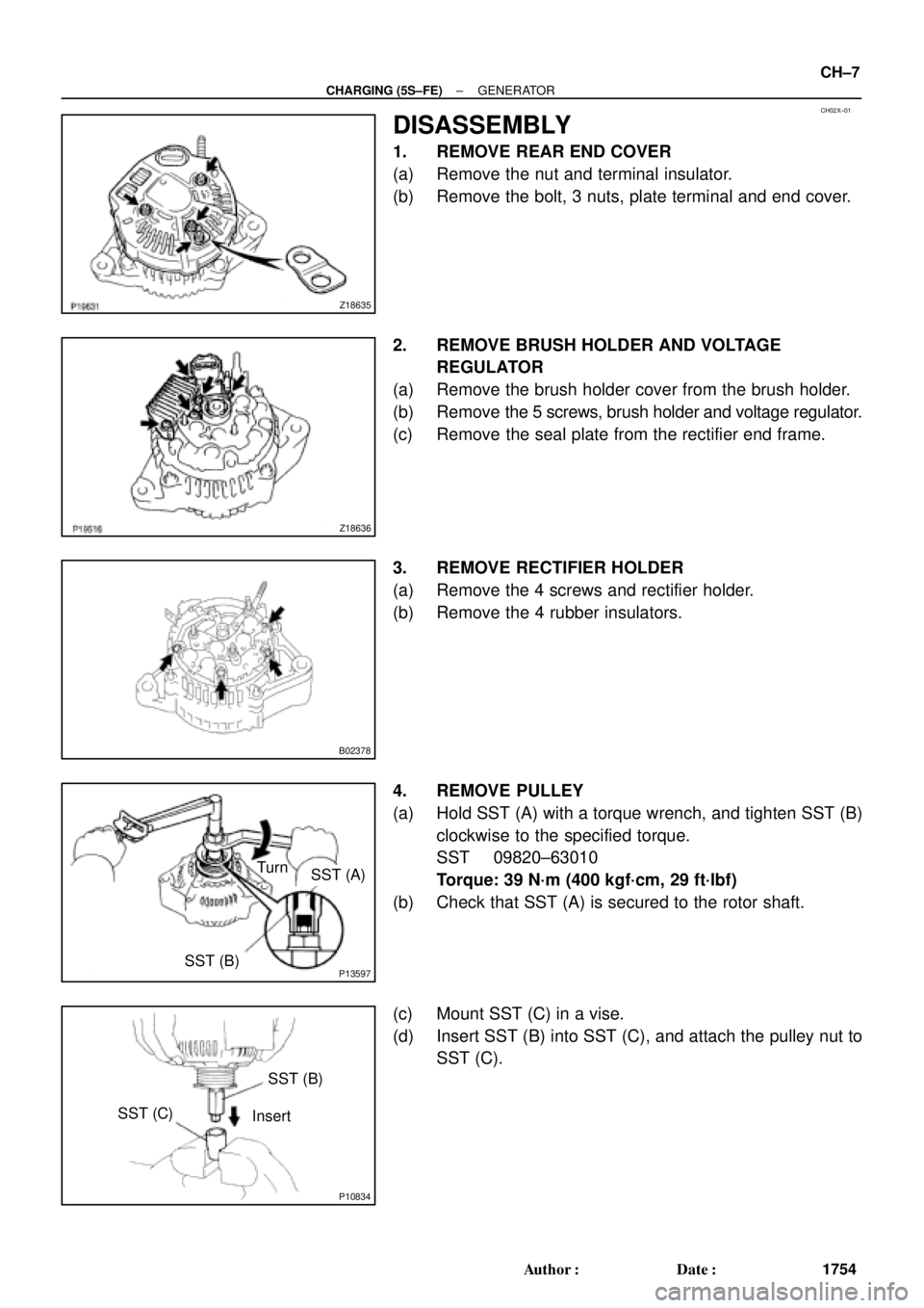
DISASSEMBLY
1. REMOVE REAR END COVER
(a) Remove the nut and terminal insulator.
(b) Remove the bolt, 3 nuts, plate terminal and end cover.
2. REMOVE BRUSH HOLDER AND VOLTAGE
REGULATOR
(a) Remove the brush holder cover from the brush holder.
(b) Remove the 5 screws, brush holder and voltage regulator.
(c) Remove the seal plate from the rectifier end frame.
3. REMOVE RECTIFIER HOLDER
(a) Remove the 4 screws and rectifier holder.
(b) Remove the 4 rubber insulators.
4. REMOVE PULLEY
(a) Hold SST (A) with a torque wrench, and tighten SST (B)
clockwise to the specified torque.
SST 09820±63010
Torque: 39 N´m (400 kgf´cm, 29 ft´lbf)
(b) Check that SST (A) is secured to the rotor shaft.
(c) Mount SST (C) in a vise.
(d) Insert SST (B) into SST (C), and attach the pulley nut to
SST (C).

(Wire Harness Side)
B+
GND
e±4±2±D
e±4±1±D
(a) Check that the battery positive voltage is 10 ± 16 V.
If voltage is not as specified, replace the")