Page 500 of 4770
19
INTERIOR
INSTRUMENT PANEL, SWITCH LAYOUT AND EQUIPMENT
�While maintaining continuity with the door trims and the console, the instrument panel provides a form with a
lowered center of gravity to emphasize a sense of freedom.
�The unique, compact meter hood expresses a sense of sportiness.
�The frequently used audio system has been located above the heater control panel, thus improving its ease of use.
Page 2031 of 4770

BO0MB±01
N20950
Instrument Panel ReinforcementNN
DD
No.2 Instrumental Panel Bracket
No.1 Instrumental Panel Bracket
No.2 Instrumental Panel Brace
QQH N
N
N
N
GG
NG
NOB
NN
Instrument Panel Brace Mount
No.1 Instrument
Panel BraceFront Pillar Garnish
Front Pillar
GarnishFront
Passenger
Airbag
Assembly
20 (200, 14)
No.2 Side Defroster Nozzle
Cowl Side Trim
Front Door Openin
g
Cover
Instrument Panel
C
Remote Control
Mirror Hole Base
Upper Column
CoverHazard Warning
Switch
Lower Finish
PlateGlove Compartment
Door Finish PlateFront Door
Inside Scuff Plate
FFF
FJ
Glove
Compartment
No.2 Lower
Panel A
A
Cluster Finish
Panel
Lower Column
Cover
Front Door
Opening
Cover
Cowl Side
TrimD
DD
D
D
F
AA
Lower Panel
InsertCoin
BoxCombination SwitchCombination
MeterRadio Assembly
Center Cluster
Finish Panel
A/C
Control Assembly
35 (360, 26)
Steering
Wheel
Pad Steering Wheel No.1 Lower
Panel
Front Door
Inside Scuff PlateFront Console
Box
Center Console
Upper PanelF
F
B
B
Rear Console
Box
N´m (kgf´cm, ft´lbf) : Specified torque BO±72
± BODYINSTRUMENT PANEL
2420 Author�: Date�:
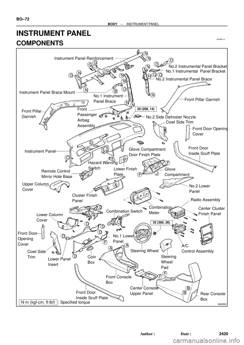
INSTRUMENT PANEL
COMPONENTS
Page 2035 of 4770

N20988
N21023
7 Clips
N21024
6 Clips BO±76
± BODYINSTRUMENT PANEL
2424 Author�: Date�:
8. REMOVE GLOVE COMPARTMENT ASSEMBLY
(a) Using a screwdriver, remove the glove compartment door
finish plate to the glove compartment box inside.
NOTICE:
When handling the airbag connector, be careful not to dam-
age the airbag wire harness.
HINT:
Tape the screwdriver tip before use.
(b) Pull up and disconnect the airbag connector.
(c) Remove the 4 screws, bolt and glove compartment as-
sembly.
9. REMOVE CENTER CONSOLE UPPER PANEL
Using a screwdriver, remove the panel, then disconnect the
connector.
HINT:
Tape the screwdriver tip before use.
10. REMOVE REAR CONSOLE BOX
Remove the 2 bolts, 2 screws and the console box.
11. REMOVE CENTER CLUSTER FINISH PANEL
Using a screwdriver, remove the panel, then disconnect the
connector.
HINT:
Tape the screwdriver tip before using.
12. REMOVE FRONT CONSOLE BOX
Remove the 2 screws and the front console box.
13. REMOVE RADIO ASSEMBLY
14. REMOVE A/C CONTROL ASSEMBLY
(See page AC±82)
15. REMOVE HAZARD WARNING SWITCH
16. REMOVE CLUSTER FINISH PANEL
(a) Remove the 2 screws.
(b) Using a screwdriver, remove the panel.
HINT:
Tape the screwdriver tip before use.
17. REMOVE COMBINATION METER
18. REMOVE REMOTE CONTROL MIRROR HOLE BASE
Page 3632 of 4770

BO0MB±01
N20950
Instrument Panel ReinforcementNN
DD
No.2 Instrumental Panel Bracket
No.1 Instrumental Panel Bracket
No.2 Instrumental Panel Brace
QQH N
N
N
N
GG
NG
NOB
NN
Instrument Panel Brace Mount
No.1 Instrument
Panel BraceFront Pillar Garnish
Front Pillar
GarnishFront
Passenger
Airbag
Assembly
20 (200, 14)
No.2 Side Defroster Nozzle
Cowl Side Trim
Front Door Openin
g
Cover
Instrument Panel
C
Remote Control
Mirror Hole Base
Upper Column
CoverHazard Warning
Switch
Lower Finish
PlateGlove Compartment
Door Finish PlateFront Door
Inside Scuff Plate
FFF
FJ
Glove
Compartment
No.2 Lower
Panel A
A
Cluster Finish
Panel
Lower Column
Cover
Front Door
Opening
Cover
Cowl Side
TrimD
DD
D
D
F
AA
Lower Panel
InsertCoin
BoxCombination SwitchCombination
MeterRadio Assembly
Center Cluster
Finish Panel
A/C
Control Assembly
35 (360, 26)
Steering
Wheel
Pad Steering Wheel No.1 Lower
Panel
Front Door
Inside Scuff PlateFront Console
Box
Center Console
Upper PanelF
F
B
B
Rear Console
Box
N´m (kgf´cm, ft´lbf) : Specified torque BO±72
± BODYINSTRUMENT PANEL
2430 Author�: Date�:
2001 CAMRY (RM819U)
INSTRUMENT PANEL
COMPONENTS
Page 3636 of 4770

N20988
N21023
7 Clips
N21024
6 Clips BO±76
± BODYINSTRUMENT PANEL
2434 Author�: Date�:
2001 CAMRY (RM819U)
8. REMOVE GLOVE COMPARTMENT ASSEMBLY
(a) Using a screwdriver, remove the glove compartment door
finish plate to the glove compartment box inside.
NOTICE:
When handling the airbag connector, be careful not to dam-
age the airbag wire harness.
HINT:
Tape the screwdriver tip before use.
(b) Pull up and disconnect the airbag connector.
(c) Remove the 4 screws, bolt and glove compartment as-
sembly.
9. REMOVE CENTER CONSOLE UPPER PANEL
Using a screwdriver, remove the panel, then disconnect the
connector.
HINT:
Tape the screwdriver tip before use.
10. REMOVE REAR CONSOLE BOX
Remove the 2 bolts, 2 screws and the console box.
11. REMOVE CENTER CLUSTER FINISH PANEL
Using a screwdriver, remove the panel, then disconnect the
connector.
HINT:
Tape the screwdriver tip before using.
12. REMOVE FRONT CONSOLE BOX
Remove the 2 screws and the front console box.
13. REMOVE RADIO ASSEMBLY
14. REMOVE A/C CONTROL ASSEMBLY
(See page AC±88 and AC±95)
15. REMOVE HAZARD WARNING SWITCH
16. REMOVE CLUSTER FINISH PANEL
(a) Remove the 2 screws.
(b) Using a screwdriver, remove the panel.
HINT:
Tape the screwdriver tip before use.
17. REMOVE COMBINATION METER
18. REMOVE REMOTE CONTROL MIRROR HOLE BASE
Page 3802 of 4770
MX04V±02
Q10340
Shift Lever Knob
Center Console Upper Panel
Heater Control Assembly
Center Cluster
Finish Panel
Front Console Box
Shift Cable Grommet RetainerRear Console Box
Shift Lever Assembly
Select Control CableShift Control Cable Shift Cable Grommet
GrommetShift Cable
Grommet
Retainer
ClipWasher
12 (120, 9)
Clip Clip
ClipWasher
Washer
4.9 (50, 43 in.´lbf)
Clip ClipClip
Clip
4.9 (50, 43 in.´lbf)
N´m (kgf´cm, ft´lbf): Specified torque
± MANUAL TRANSAXLE (S51)SHIFT LEVER AND CONTROL CABLE
MX±43
1893 Author�: Date�:
SHIFT LEVER AND CONTROL CABLE
COMPONENTS
Page 3851 of 4770
MX05K±01
Q10281
Shift Lever Knob
Center Console Upper Panel
Heater Control Assembly
Center Cluster
Finish Panel
Front Console Box
12 (120, 9)
Shift Lever Assembly
Clip
Washer Shift Control Cable
Select Control Cable Clip
Clip ClipClip
Clip
Clip Shift Cable Grommet Retainer
4.9 (50, 43 in.´lbf)Shift Cable
Grommet
Grommet Shift Cable Grommet
Retainer
4.9 (50, 43 in.´lbf)
Washer
Clip
N´m (kgf´cm, ft´lbf): Specified torqueRear Console Box
Washer
± MANUAL TRANSAXLE (E153)SHIFT LEVER AND CONTROL CABLE
MX±49
1850 Author�: Date�:
SHIFT LEVER AND CONTROL CABLE
COMPONENTS
Page 4451 of 4770

Toyota Supports ASE CertificationPage 1 of 1
BO005±99
Title:
CAMRY CENTER CONSOLE LATCH
IMPROVEMENTS
Models:
'97±'99 Camry
Technical Service
BULLETIN
March 26, 1999
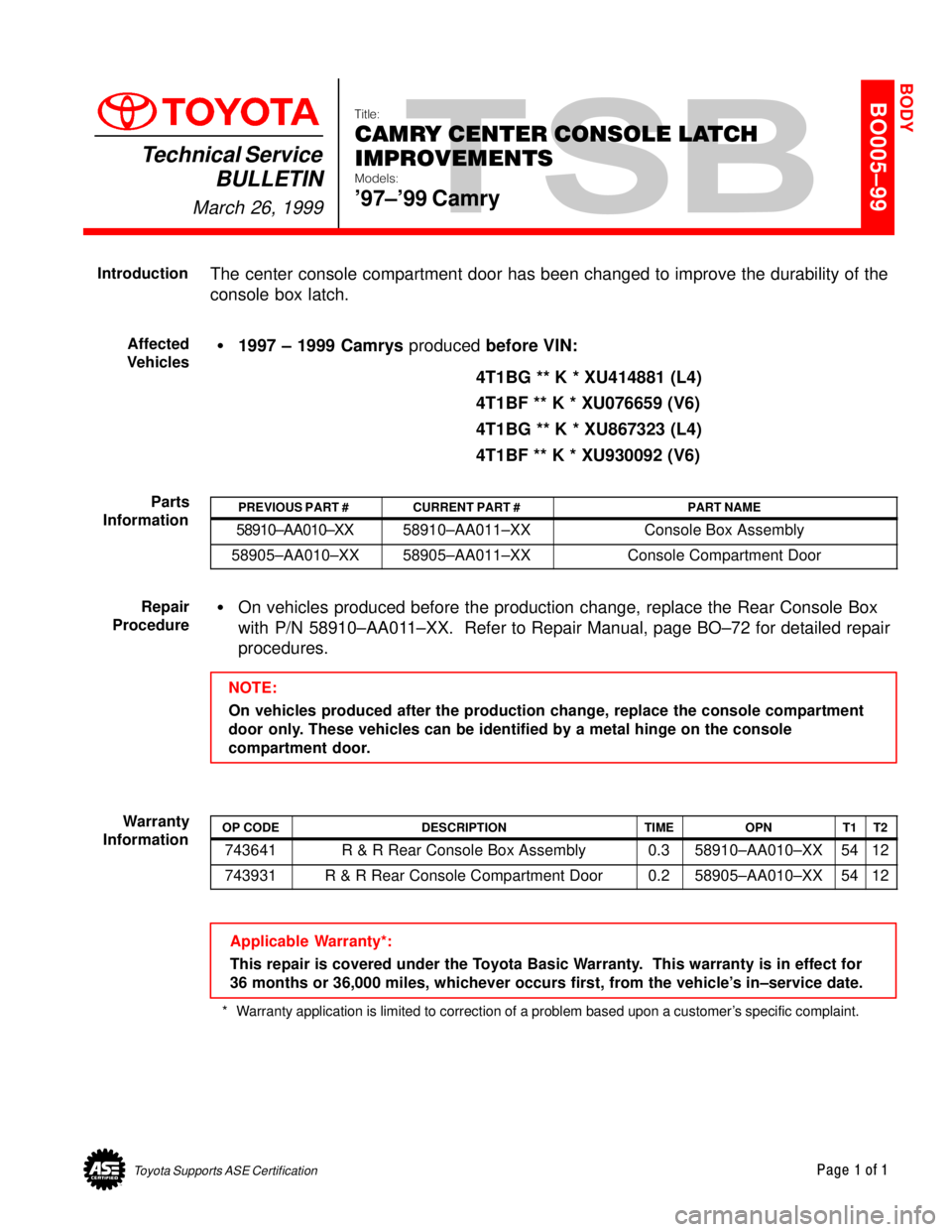
The center console compartment door has been changed to improve the durability of the
console box latch.
�1997 ± 1999 Camrys produced before VIN:
4T1BG ** K * XU414881 (L4)
4T1BF ** K * XU076659 (V6)
4T1BG ** K * XU867323 (L4)
4T1BF ** K * XU930092 (V6)
PREVIOUS PART #CURRENT PART #PART NAME
58910±AA010±XX58910±AA011±XXConsole Box Assembly
58905±AA010±XX58905±AA011±XXConsole Compartment Door
�On vehicles produced before the production change, replace the Rear Console Box
with P/N 58910±AA011±XX. Refer to Repair Manual, page BO±72 for detailed repair
procedures.
NOTE:
On vehicles produced after the production change, replace the console compartment
door only. These vehicles can be identified by a metal hinge on the console
compartment door.
OP CODEDESCRIPTIONTIMEOPNT1T2
743641R & R Rear Console Box Assembly0.358910±AA010±XX5412
743931R & R Rear Console Compartment Door0.258905±AA010±XX5412
Applicable Warranty*:
This repair is covered under the Toyota Basic Warranty. This warranty is in effect for
36 months or 36,000 miles, whichever occurs first, from the vehicle's in±service date.
* Warranty application is limited to correction of a problem based upon a customer's specific complaint.
BODY
Introduction
Affected
Vehicles
Parts
Information
Repair
Procedure
Warranty
Information