Page 453 of 4770

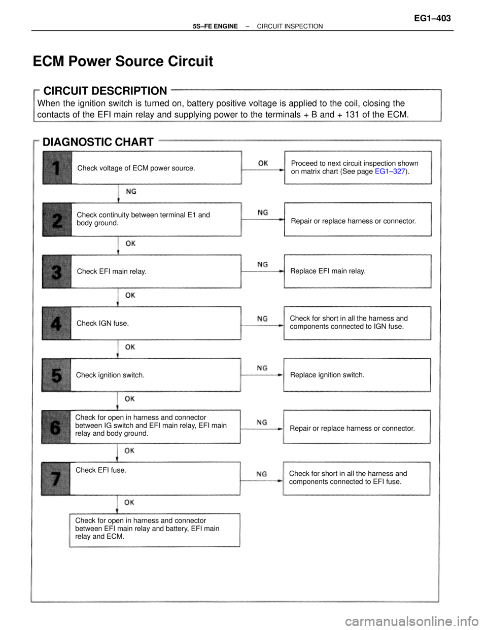
CIRCUIT DESCRIPTION
When the ignition switch is turned on, battery positive voltage is applied to the coil, closing the
contacts of the EFI main relay and supplying power to the terminals + B and + 131 of the ECM.
Check for open in harness and connector
between IG switch and EFI main relay, EFI main
relay and body ground.
Check for open in harness and connector
between EFI main relay and battery, EFI main
relay and ECM.Check continuity between terminal E1 and
body ground.Proceed to next circuit inspection shown
on matrix chart (See page EG1±327).
Check for short in all the harness and
components connected to IGN fuse.
Check for short in all the harness and
components connected to EFI fuse.
ECM Power Source Circuit
Repair or replace harness or connector.
Repair or replace harness or connector. Check voltage of ECM power source.
DIAGNOSTIC CHART
Replace ignition switch.
Check EFI fuse.Replace EFI main relay.
Check ignition switch.Check EFI main relay.
Check IGN fuse.
± 5S±FE ENGINECIRCUIT INSPECTIONEG1±403
Page 458 of 4770
CIRCUIT DESCRIPTION
Battery positive voltage is supplied to terminal BATT of the ECM even when the ignition switch is off
for use by the diagnostic trouble code memory and air±fuel ratio adaptive control value memory, etc.
Back Up Power Source Circuit
Proceed to next circuit inspection
shown on matrix chart (See page EG1±327).Check and repair harness or connector
between battery, EFI fuse and ECU. Check for short in all the harness and
components connected to EFI fuse.
DIAGNOSTIC CHART
Check operation for the back up. Check voltage of terminal6ATT.
WIRING DIAGRAM
Check and replace ECM. Check EFI fuse.
± 5S±FE ENGINECIRCUIT INSPECTIONEG1±408
Page 459 of 4770
Remove glove compartment.
(See page EG1±234)
Measure voltage between terminal BATT of en±
gine control module connector and body ground.
Voltage: 9 ±14 V
Check voltage between terminal BATT of engine control module
connector and body ground.
Are the diagnostic trouble codes still in the memory when the
ignition switch is turned OFF?
Check and repair harness or connector
between engine control module and EN
fuse, EFI fuse and battery. Remove EFI fuse from J/B No.2.
Check continuity of EFI fuse.
Continuity
Check for short in all the harness and
components connected to EFI fuse
(See attached wiring diagram).
Proceed to next circuit inspection shown on
matrix chart (See page EG1±327).Check and replace engine control module.
INSPECTION PROCEDURE
Check EFI fuse.
Others
YES
± 5S±FE ENGINECIRCUIT INSPECTIONEG1±409
Page 460 of 4770
Reference INSPECTION USING OSCILLOSCOPE
INJECTOR SIGNAL WAVEFORM
wWith the engine idling measure waveform between terminals #10, #20 (#1, #2, #3 and #4*)
and E01 of engine control module.
HINT: The correct waveform appears as shown in the illustration on the below.
CIRCUIT DESCRIPTION
The injectors are provided to the intake manifold. They inject fuel into the cylinders based on the
signals from the engine control module.
Check continuity between terminals E01, E02
and body ground. Check voltage of terminals #10 and #20
(#1. #2. #3 and #4*).
Check for open in harness and connector
between ECM and battery.Check for short in all the harness and
components connected to AM2 fuse.
*: Only for California specification vehicles.
Injector Circuit
Repair or replace harness or connector.
DIAGNOSTIC CHART
Check operation for injectors.
Check and replace ECM.Replace injector. Check AM2 fuse.
± 5S±FE ENGINECIRCUIT INSPECTIONEG1±410
Page 929 of 4770

'99camry U
215
Parts and tools
Here is a list of parts and tools you will
need on performing do±it±yourself mainte-
nance. Remember all Toyota parts are de-
signed in metric sizes, so your tools must
be metric.
Checking the engine oil level
Parts (if level is low):
�Engine oil API grade SJ, ºEnergy±Con-
servingº or ILSAC multigrade having
viscosity proper for your climate
Tools:
�Rag or paper towel
�Funnel (only for adding oil)
Checking the engine coolant level
Parts (if level is low):
�ºToyota Long Life Coolantº or equiva-
lent
See Chapter 7±2 for details about cool-
ant type selection.
�Demineralized or distilled water
Tools:
�Funnel (only for adding coolant)Checking brake fluid
Parts (if level is low):
�SAE J1703 or FMVSS No.116 DOT 3
brake fluid
Tools:
�Rag or paper towel
�Funnel (only for adding fluid)
Checking power steering fluid
Parts (if level is low):
�Automatic transmission fluid
DEXRON)II or III
Tools:
�Rag or paper towel
�Funnel (only for adding fluid)
Checking battery condition
Tools:
�Warm water
�Baking soda
�Grease
�Conventional wrench (for terminal
clamp bolts)Checking and replacing fuses
Parts (if replacement is necessary):
�Genuine Toyota fuse or equivalent with
same amperage rating as original
Adding washer fluid
Parts:
�Water
�Washer fluid containing antifreeze (for
winter use)
Tools:
�Funnel
Replacing light bulbs
Parts:
�Bulb with same number and wattage
rating as original (See charts in ºRe-
placing light bulbsº in Chapter 7±3.)
Tools:
�Screwdriver
�Flat±bladed screwdriver
Page 1158 of 4770

B
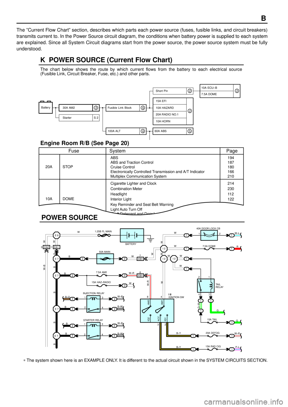
The ºCurrent Flow Chartº section, describes which parts each power source (fuses, fusible links, and circuit breakers)
transmits current to. In the Power Source circuit diagram, the conditions when battery power is supplied to each system
are explained. Since all System Circuit diagrams start from the power source, the power source system must be fully
understood.
Theft Deterrent and Door Lock Control
K POWER SOURCE (Current Flow Chart)
11
1
EA1 1EA2 3
7
EB16
E 6
E 7I 2I 2
I 2
E 7
E 7
E 7
2
1
1
2
2
2
2
2
B
B
W W
B B B B BW±B
B
B
B B±O
B±W
W±B
B±W STARTER RELAY INJECTION RELAY15A HAZ±RADIO7.5A AM250A MAIN 1.25B FL MAIN
BATTERY
WWW
W W W
R W±L
W
W
G±W
G
15A TAIL
20A DEFOG
15A RAD CIGTA I L
RELAY 7.5A DOME 40A DOOR LOCK CB
2 1
1 2
4 8
2 3
3 4
G
W±R
P±L B±Y
B±Y
W±R
AM2 IG2
ACC
IG1AM1W W
W±R
W W
W±B
21
1
1
1
1
2
2
2
2
3
4
3
4 1
2
1
22
1
11
1
IGNITION SW I 8
Battery
30A AM2
2
Starter S 220A RADIO NO.1
10A HORN
15A EFI
7.5A DOMEShort Pin
10A HAZARD
The chart below shows the route by which current flows from the battery to each electrical source
(Fusible Link, Circuit Breaker, Fuse, etc.) and other parts.
Engine Room R/B (See Page 20)
ABS
ABS and Traction Control
Cruise Control
Electronically Controlled Transmission and A/T Indicator
Multiplex Communication System
Cigarette Lighter and Clock
Key Reminder and Seat Belt Warning STOP
Fuse Page
194
214
11 2
System
DOME 20A
10ACombination Meter
Headlight
Interior Light
2
2
6 100A ALT
EB1
POWER SOURCE
Light Auto Turn Off187
180
166
210
230
122
10A ECU±B
5 60A ABS
2
6 Fusible Link Block2
* The system shown here is an EXAMPLE ONLY. It is different to the actual circuit shown in the SYSTEM CIRCUITS SECTION.
Page 1505 of 4770

K POWER SOURCE (Current Flow Chart)
Fusible Link Block (See Page 19)
FuseSystemPage
50AHTRAir Conditioning (Automatic A/C)
Air Conditioning (Manual A/C)292
300
100AALT
Charging
Headlight (w/ Daytime Running Light)
Illumination
Light Auto Turn Off
Radiator Fan and Condenser Fan
Taillight
Theft Deterrent (TMC Made)
Theft Deterrent (TMMK Made)
Wireless Door Lock Control (TMC Made)
Wireless Door Lock Control (TMMK Made)62
100
126
11 0
288
132
182
188
162
172
Instrument Panel J/B (See Page 20)
FuseSystemPage
5AIGN
Charging
Combination Meter
Electronically Controlled Transmission and A/T Indicator (1MZ±FE)
Electronically Controlled Transmission and A/T Indicator (5S±FE)
Engine Control (1MZ±FE)
Engine Control (5S±FE)
SRS62
280
202
210
66
82
245
5ASTARTER
Combination Meter
Electronically Controlled Transmission and A/T Indicator (1MZ±FE)
Electronically Controlled Transmission and A/T Indicator (5S±FE)
Engine Control (1MZ±FE)
Engine Control (5S±FE)
Starting and Ignition (1MZ±FE)
Starting and Ignition (5S±FE)280
202
210
66
82
54
58
7.5AOBDEngine Control (1MZ±FE)
Engine Control (5S±FE)66
82
7.5APANEL
Cigarette Lighter and Clock
Combination Meter
Illumination258
280
126
7.5ARAD±NO.2
Auto Antenna
Radio and Player (Built±In Type Amplifier)
Radio and Player (Separate Type Amplifier)272
278
274
7.5ATURNTurn Signal and Hazard Warning Light11 4
10AGAUGE
ABS (TMC Made)
ABS (TMMK Made)
ABS and Traction Control
Back±Up Light
Charging234
240
226
138
62
*These are the page numbers of the first page on which the related system is shown.
Page 1507 of 4770

K POWER SOURCE (Current Flow Chart)
FuseSystemPage
15ASTOP
ABS (TMC Made)
ABS (TMMK Made)
ABS and Traction Control
Cruise Control
Electronically Controlled Transmission and A/T Indicator (1MZ±FE)
Electronically Controlled Transmission and A/T Indicator (5S±FE)
Engine Control (1MZ±FE)
Engine Control (5S±FE)
Shift Lock
Stop Light234
240
226
218
202
210
66
82
252
11 8
25AWIPERWiper and Washer140
25ADOOR
Door Lock Control (TMC Made)
Door Lock Control (TMMK Made)
Moon Roof
Power Window
Theft Deterrent (TMC Made)
Theft Deterrent (TMMK Made)
Wireless Door Lock Control (TMC Made)
Wireless Door Lock Control (TMMK Made)150
156
194
144
182
188
162
172
30APOWER
Door Lock Control (TMC Made)
Door Lock Control (TMMK Made)
Moon Roof
Power Seat
Power Window150
156
194
198
144
40AAM1Charging
Radiator Fan and Condenser Fan62
288
40ADEFRear Window Defogger and Mirror Heater268
Engine Room J/B No.2 (See Page 22)
FuseSystemPage
5AALT±SCharging62
7.5ADOME
Cigarette Lighter and Clock
Combination Meter
Headlight (w/ Daytime Running Light)
Interior Light
Key Reminder and Seat Belt Warning
Light Auto Turn Off
Moon Roof
Theft Deterrent (TMC Made)
Theft Deterrent (TMMK Made)
Wireless Door Lock Control (TMC Made)
Wireless Door Lock Control (TMMK Made)258
280
100
122
260
11 0
194
182
188
162
172
*These are the page numbers of the first page on which the related system is shown.