Page 102 of 4770
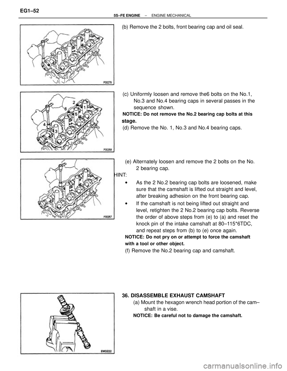
(e) Alternately loosen and remove the 2 bolts on the No.
2 bearing cap.
HINT:
wAs the 2 No.2 bearing cap bolts are loosened, make
sure that the camshaft is lifted out straight and level,
after breaking adhesion on the front bearing cap.
wIf the camshaft is not being lifted out straight and
level, retighten the 2 No.2 bearing cap bolts. Reverse
the order of above steps from (e) to (a) and reset the
knock pin of the intake camshaft at 80±115*6TDC,
and repeat steps from (b) to (e) once again.
NOTICE: Do not pry on or attempt to force the camshaft
with a tool or other object.
(f) Remove the No.2 bearing cap and camshaft. (c) Uniformly loosen and remove the6 bolts on the No.1,
No.3 and No.4 bearing caps in several passes in the
sequence shown.
NOTICE: Do not remove the No.2 bearing cap bolts at this
stage.
(d) Remove the No. 1, No.3 and No.4 bearing caps.
36. DISASSEMBLE EXHAUST CAMSHAFT
(a) Mount the hexagon wrench head portion of the cam±
shaft in a vise.
NOTICE: Be careful not to damage the camshaft.
(b) Remove the 2 bolts, front bearing cap and oil seal.
± 5S±FE ENGINEENGINE MECHANICALEG1±52
Page 1165 of 4770
E GLOSSARY OF TERMS AND SYMBOLS
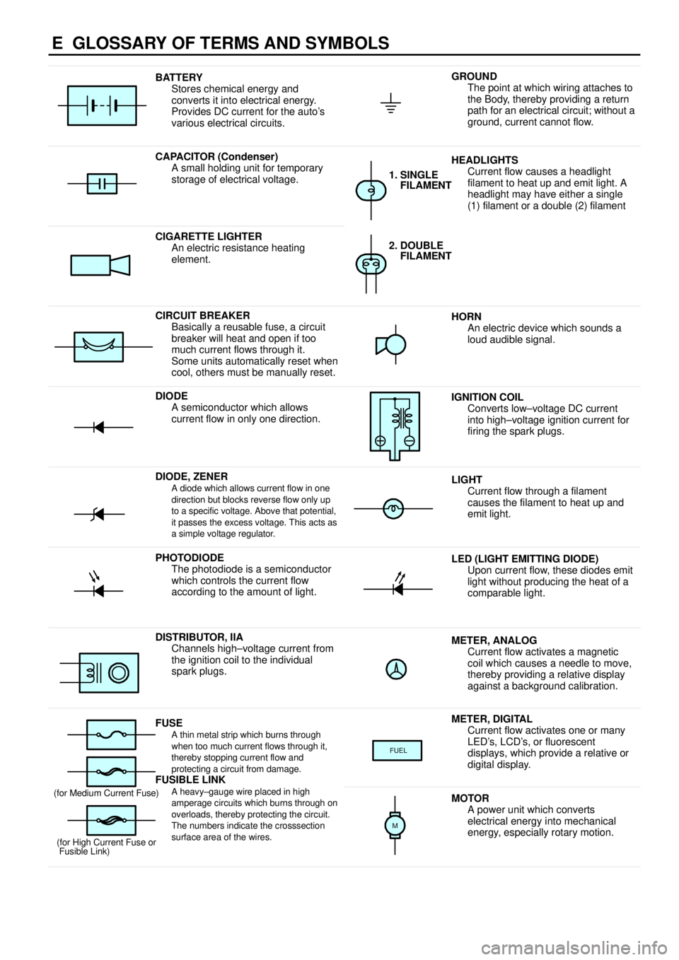
BATTERY
Stores chemical energy and
converts it into electrical energy.
Provides DC current for the auto's
various electrical circuits.GROUND
The point at which wiring attaches to
the Body, thereby providing a return
path for an electrical circuit; without a
ground, current cannot flow.
CAPACITOR (Condenser)
A small holding unit for temporary
storage of electrical voltage.HEADLIGHTS
Current flow causes a headlight
filament to heat up and emit light. A
headlight may have either a single
(1) filament or a double (2) filament
1. SINGLE
FILAMENT
CIGARETTE LIGHTER
An electric resistance heating
element.2. DOUBLE
FILAMENT
CIRCUIT BREAKER
Basically a reusable fuse, a circuit
breaker will heat and open if too
much current flows through it.
Some units automatically reset when
cool, others must be manually reset.HORN
An electric device which sounds a
loud audible signal.
DIODE
A semiconductor which allows
current flow in only one direction.IGNITION COIL
Converts low±voltage DC current
into high±voltage ignition current for
firing the spark plugs.
DIODE, ZENERA diode which allows current flow in one
direction but blocks reverse flow only up
to a specific voltage. Above that potential,
it passes the excess voltage. This acts as
a simple voltage regulator.LIGHT
Current flow through a filament
causes the filament to heat up and
emit light.
PHOTODIODE
The photodiode is a semiconductor
which controls the current flow
according to the amount of light.LED (LIGHT EMITTING DIODE)
Upon current flow, these diodes emit
light without producing the heat of a
comparable light.
DISTRIBUTOR, IIA
Channels high±voltage current from
the ignition coil to the individual
spark plugs.METER, ANALOG
Current flow activates a magnetic
coil which causes a needle to move,
thereby providing a relative display
against a background calibration.
FUSEA thin metal strip which burns through
when too much current flows through it,
thereby stopping current flow and
protecting a circuit from damage.
FUSIBLE LINK
METER, DIGITAL
Current flow activates one or many
LED's, LCD's, or fluorescent
displays, which provide a relative or
digital display.
FUEL
FUSIBLE LINK
A heavy±gauge wire placed in high
amperage circuits which burns through on
overloads, thereby protecting the circuit.
The numbers indicate the crosssection
surface area of the wires.(for Medium Current Fuse)
(for High Current Fuse or
Fusible Link)MOTOR
A power unit which converts
electrical energy into mechanical
energy, especially rotary motion.
M
Page 3431 of 4770
P03358
8 0 ± 11 5°
Knock
Pin
P03359
P03360
1 2
3 45 6
P03361
± ENGINE MECHANICAL (5S±FE)CYLINDER HEAD
EM±39
1211 Author�: Date�:
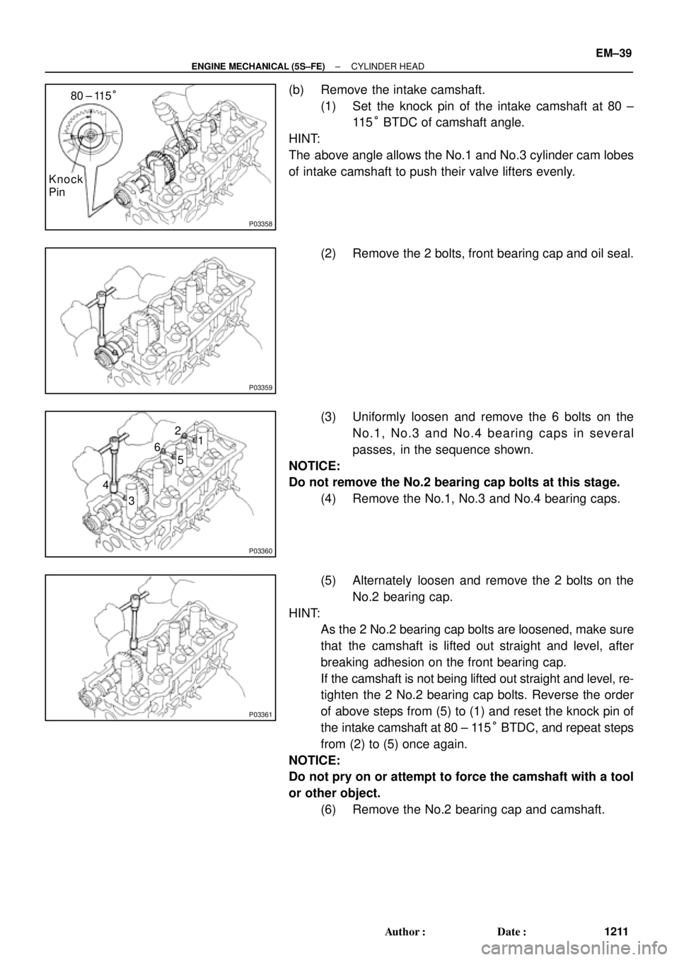
(b) Remove the intake camshaft.
(1) Set the knock pin of the intake camshaft at 80 ±
11 5° BTDC of camshaft angle.
HINT:
The above angle allows the No.1 and No.3 cylinder cam lobes
of intake camshaft to push their valve lifters evenly.
(2) Remove the 2 bolts, front bearing cap and oil seal.
(3) Uniformly loosen and remove the 6 bolts on the
No.1, No.3 and No.4 bearing caps in several
passes, in the sequence shown.
NOTICE:
Do not remove the No.2 bearing cap bolts at this stage.
(4) Remove the No.1, No.3 and No.4 bearing caps.
(5) Alternately loosen and remove the 2 bolts on the
No.2 bearing cap.
HINT:
�As the 2 No.2 bearing cap bolts are loosened, make sure
that the camshaft is lifted out straight and level, after
breaking adhesion on the front bearing cap.
�If the camshaft is not being lifted out straight and level, re-
tighten the 2 No.2 bearing cap bolts. Reverse the order
of above steps from (5) to (1) and reset the knock pin of
the intake camshaft at 80 ± 115° BTDC, and repeat steps
from (2) to (5) once again.
NOTICE:
Do not pry on or attempt to force the camshaft with a tool
or other object.
(6) Remove the No.2 bearing cap and camshaft.
Page 4765 of 4770
M.I.L. ªONº 1MZ±FE ENGINE MISFIRE DTC P0300 ± P0306 ± EG008-04April 28, 2004
Page 3 of 3
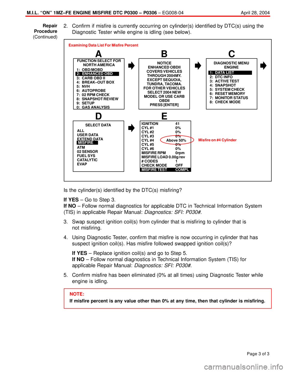
2. Confirm if misfire is currently occurring on cylinder(s) identified by DTC(s) using the
Diagnostic Tester while engine is idling (see below).
FUNCTION SELECT FOR
NORTH AMERICA
B A
DIAGNOSTIC MENU
ENGINE
C
ALL
USER DATA
EXTEND DATA
AT M
02 SENSOR
FUEL SYS
CATALYTIC
EVAP
E
SELECT DATA
D
MISFIRE
1: OBD/MOBD
3: CARB OBD II
4: BREAK±OUT BOX
5: NVH
6: AUTOPROBE
7: 02 RPM CHECK
8: SNAPSHOT REVIEW
9: SETUP
0: GAS ANALYSIS2: ENHANCED OBD
2: DTC INFO
3: ACTIVE TEST
4: SNAPSHOT
5: SYSTEM CHECK
6: RESET MEMORY
7: MONITOR STATUS
8: CHECK MODE1: DATA LIST Examining Data List For Misfire Percent
NOTICE
ENHANCED OBDII
COVERS VEHICLES
THROUGH 2004MY.
EXCEPT SEQUOIA,
TUNDRA, TACOMA.
FOR OTHER VEHICLES
SELECT 2004 NEW
MODEL OR USE CARB
OBDII
PRESS [ENTER]
IGNITION 41
CYL #1 0%
CYL #2 0%
CYL #3 0%
CYL #4 Above 50%
CYL #5 0%
CYL #6 0%
MISFIRE RPM 0rpm
MISFIRE LOAD 0.00g/rev
# CODES 1
CHECK MODE OFF
MISFIRE TEST COMPL
Misfire on #4 Cylinder
Is the cylinder(s) identified by the DTC(s) misfiring?
If YES ± Go to Step 3.
If NO ± Follow normal diagnostics for applicable DTC in Technical Information System
(TIS) in applicable Repair Manual:
Diagnostics: SFI: P030#.
3. Swap suspect ignition coil(s) from cylinder that is misfiring to cylinder that is
not misfiring.
4. Using Diagnostic Tester, confirm that misfire is now occurring in cylinder that has
suspect ignition coil(s). Has misfire followed swapped ignition coil(s)?
If YES ± Replace ignition coil(s) and go to Step 5.
If NO ± Follow normal diagnostics in Technical Information System (TIS) for
applicable Repair Manual:
Diagnostics: SFI: P030#.
5. Confirm misfire has been eliminated (0% at all times) using Diagnostic Tester while
engine is idling.
NOTE:
If misfire percent is any value other than 0% at any time, then that cylinder is misfiring. Repair
Procedure
(Continued)