BE±8
± BODY ELECTRICALBODY ELECTRICAL SYSTEM
2228 Author�: Date�:
Shift indicator lights do not light up.
1. Bulb
2. Meter Circuit Plate
3. Park/Neutral Position Switch (A140E)
(A541E)
4. Wire Harness±
BE±46
DI±424
DI±479
±
Only one shift indicator does not light up.1. Bulb
2. Meter Circuit Plate±
BE±46
Malfunction indicator light does not light up.
1. Bulb
2. ECM
3. Meter Circuit Plate
4. Wire Harness±
±
BE±46
±
SLIP indicator light does not light up.
1. Bulb
2. Traction ECU
3. Meter Circuit Plate
4. Wire Harness±
±
BE±46
±
TRAC OFF indicator light does not light up.
1. Bulb
2. Traction ECU
3. Meter Circuit Plate
4. Wire Harness±
±
BE±46
±
Security indicator light does not light up.
1. Bulb
2. Security ECU
3. Meter Circuit Plate
4. Wire Harness±
±
BE±46
±
Indicator lights do not light up. (Except Turn, Hi±beam and
security)1. GAUGE Fuse (I/P J/B No.1)
2. Wire Harness±
±
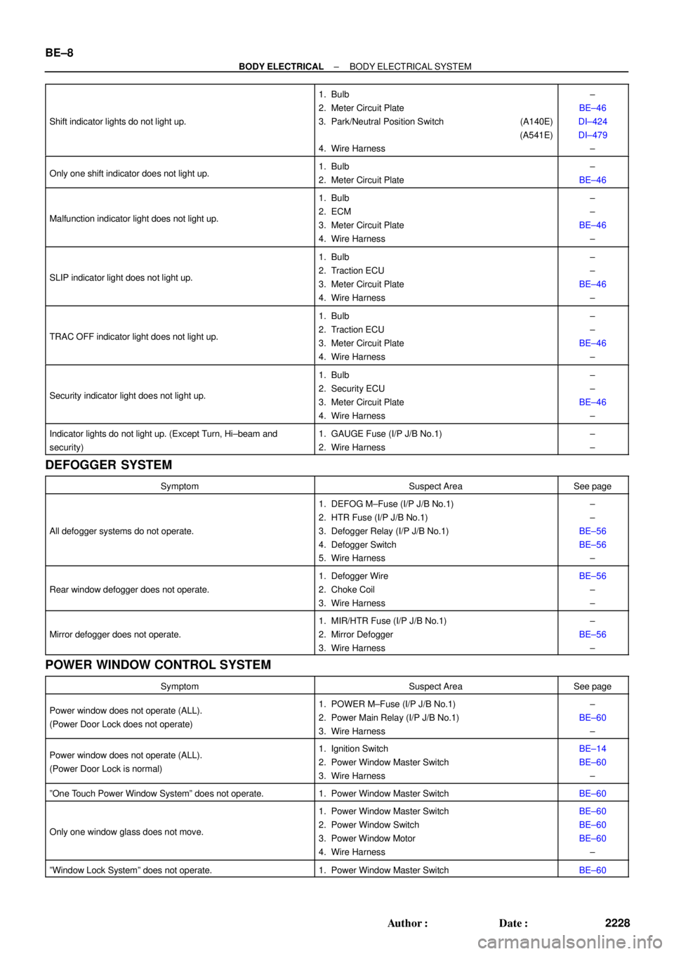
DEFOGGER SYSTEM
SymptomSuspect AreaSee page
All defogger systems do not operate.
1. DEFOG M±Fuse (I/P J/B No.1)
2. HTR Fuse (I/P J/B No.1)
3. Defogger Relay (I/P J/B No.1)
4. Defogger Switch
5. Wire Harness±
±
BE±56
BE±56
±
Rear window defogger does not operate.
1. Defogger Wire
2. Choke Coil
3. Wire HarnessBE±56
±
±
Mirror defogger does not operate.
1. MIR/HTR Fuse (I/P J/B No.1)
2. Mirror Defogger
3. Wire Harness±
BE±56
±
POWER WINDOW CONTROL SYSTEM
SymptomSuspect AreaSee page
Power window does not operate (ALL).
(Power Door Lock does not operate)1. POWER M±Fuse (I/P J/B No.1)
2. Power Main Relay (I/P J/B No.1)
3. Wire Harness±
BE±60
±
Power window does not operate (ALL).
(Power Door Lock is normal)1. Ignition Switch
2. Power Window Master Switch
3. Wire HarnessBE±14
BE±60
±
ºOne Touch Power Window Systemº does not operate.1. Power Window Master SwitchBE±60
Only one window glass does not move.
1. Power Window Master Switch
2. Power Window Switch
3. Power Window Motor
4. Wire HarnessBE±60
BE±60
BE±60
±
ºWindow Lock Systemº does not operate.1. Power Window Master SwitchBE±60
BE0AM±03
N20315
Switch side:
1 2
3
4 5 6
N20314
ON3 4 5
Z08467
1
2
3456 Wire harness side:
S±6±1
N14863
1
2 35 12
35 BE±56
± BODY ELECTRICALDEFOGGER SYSTEM
2276 Author�: Date�:
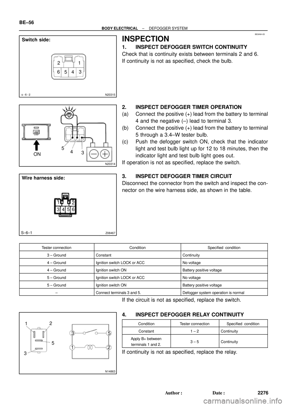
INSPECTION
1. INSPECT DEFOGGER SWITCH CONTINUITY
Check that is continuity exists between terminals 2 and 6.
If continuity is not as specified, check the bulb.
2. INSPECT DEFOGGER TIMER OPERATION
(a) Connect the positive (+) lead from the battery to terminal
4 and the negative (±) lead to terminal 3.
(b) Connect the positive (+) lead from the battery to terminal
5 through a 3.4±W tester bulb.
(c) Push the defogger switch ON, check that the indicator
light and test bulb light up for 12 to 18 minutes, then the
indicator light and test bulb light goes out.
If operation is not as specified, replace the switch.
3. INSPECT DEFOGGER TIMER CIRCUIT
Disconnect the connector from the switch and inspect the con-
nector on the wire harness side, as shown in the table.
Tester connectionConditionSpecified condition
3 ± GroundConstantContinuity
4 ± GroundIgnition switch LOCK or ACCNo voltage
4 ± GroundIgnition switch ONBattery positive voltage
5 ± GroundIgnition switch LOCK or ACCNo voltage
5 ± GroundIgnition switch ONBattery positive voltage
±Connect terminals 3 and 5.Defogger system operation is normal
If the circuit is not as specified, replace the switch.
4. INSPECT DEFOGGER RELAY CONTINUITY
ConditionTester connectionSpecified condition
Constant1 ± 2Continuity
Apply B+ between
terminals 1 and 2.3 ± 5Continuity
If continuity is not as specified, replace the relay.