Page 2530 of 4770
A03017
A03418
ON
E9 Connector
EGR
OFF
Air
FilterON
Air
Air
E
G E
VSV is ON
VSV is OFF Air
G w/o Immobiliser
w/ Immobiliser
OFF
ON EGR
E8 Connector
DI±110
± DIAGNOSTICSENGINE (5S±FE)
345 Author�: Date�:
OBD II scan tool (excluding TOYOTA hand±held tester):
1 Check connection of vacuum hose and EGR hose (See page EC±12).
NG Repair or replace.
OK
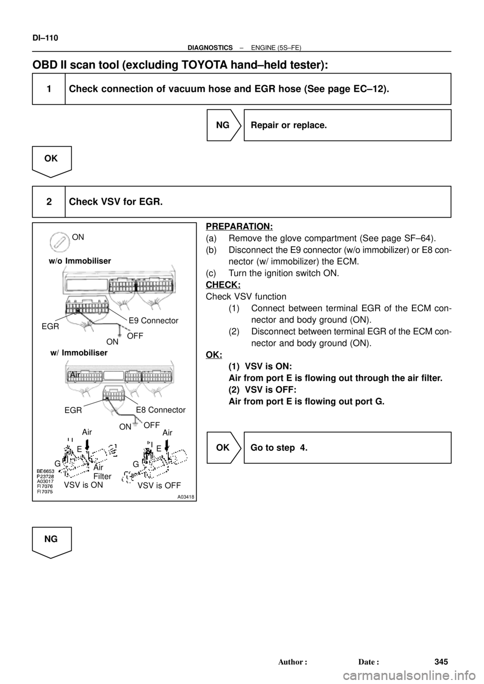
2 Check VSV for EGR.
PREPARATION:
(a) Remove the glove compartment (See page SF±64).
(b) Disconnect the E9 connector (w/o immobilizer) or E8 con-
nector (w/ immobilizer) the ECM.
(c) Turn the ignition switch ON.
CHECK:
Check VSV function
(1) Connect between terminal EGR of the ECM con-
nector and body ground (ON).
(2) Disconnect between terminal EGR of the ECM con-
nector and body ground (ON).
OK:
(1) VSV is ON:
Air from port E is flowing out through the air filter.
(2) VSV is OFF:
Air from port E is flowing out port G.
OK Go to step 4.
NG
Page 2871 of 4770

DI1KA±01
FI6810
E10 E9 E8E7
34 33 32 31 30 29 28 2717 18 19 20 21 22 23 24 25 2611 12 13 14 15 161 2 3 4 5 6 7 8 9 101 2 3 4 5 6 7 8
9 10 11 12 13
14 15 16 17 18 19 20 21
22 23 24 25 26 27 28 1 2 3 4
5 6 7
8 9 10 11
12 13 14 15 16 1 2 3 4 5 6
7 8 9 10 11
12 13 14 15 16 17
18 19 20 21 22
ECM Terminals
± DIAGNOSTICSAUTOMATIC TRANSAXLE (A541E)
DI±451
686 Author�: Date�:
TERMINALS OF ECM
Except California, w/ Engine Immobilizer and / or TRAC:
Symbols (Terminals No.)Wiring ColorConditionSTD Voltage (V)
IG ON10 ~ 14
S1 e E1 (E10±11 e E8±16)
V e BR1st or 2nd gear10 ~ 14S1 e E1 (E10 11 e E8 16)
V e BR
3rd or O/D gearBelow 1
IG ONBelow 1
S2 e E1 (E10±17 e E8±16)L±B e BR1st or 2nd gear10 ~ 14S2 e E1 (E10 17 e E8 16)LB e BR
3rd or O/D gearBelow 1
SLE1 (E10 27E8 16)PLBRIG ONBelow 1SL e E1 (E10±27 e E8±16)P±L e BRVehicle driving under lock±up position10 ~ 14
NC2+ e NC2± (E9±9 e E9±4)R e GEngine is runningPulse signal is output
Below 1 e 4 ~ 5
SLN+ e SLN±
(E10±2 e E 8±2)W±L e B±YIG ON10 ~ 14
OD1 e E1 (E7±7 e E8±16)Y±B e BRIG ON5 ~ 6
OD2E1 (E7 6E8 16)GOBRO/D main switch ON10 ~ 14OD2 e E1 (E7±6 e E8±16)G±O e BRO/D main switch OFFBelow 1
LE1 (E7 1E8 16)YBRIG ON and Shift lever L position10 ~ 14L e E1 (E7±1 e E8±16)Y e BRIG ON and Shift lever other than L positionBelow 1
2E1 (E7 10E8 16)*1, *3 L±W e BRIG ON and Shift lever 2 position10 ~ 142 e E1 (E7±10 e E8±16)1, 3 LW e BR
*2, *4 O e BRIG ON and Shift lever other than 2 positionBelow 1
RE1 (E7 15E8 16)RBBRIG ON and Shift lever R position10 ~ 14R e E1 (E7±15 e E8±16)R±B e BRIG ON and Shift lever other than R positionBelow 1
NSW e E1BWBRIG ON and Shift lever P or N position10 ~ 14NSW e E1
(E10±14 e E8±16)B±W e BRIG ON and Shift lever other than P or N positionBelow 1
*1: w/ Engine immobilizer system
*2: w/o Engine immobilizer system
*3 TMC made ex. USA w/ TRAC
*4: TMMK made, TMC made USA w/ TRAC
Page 2872 of 4770

687 Author�: Date�:
California, w/ Engine Immobilizer and / or TRAC:
Symbols (Terminals No.)Wiring ColorCondition")
D01054
E10
E9
E8 E11E7
ECM Terminals DI±452
± DIAGNOSTICSAUTOMATIC TRANSAXLE (A541E)
687 Author�: Date�:
California, w/ Engine Immobilizer and / or TRAC:
Symbols (Terminals No.)Wiring ColorConditionSTD Voltage (V)
IG ON10 ~ 14
S1 e E1 (E11±7 e E10±17)
V e BR1st or 2nd gear10 ~ 14S1 e E1 (E11 7 e E10 17)
V e BR
3rd or O/D gearBelow 1
IG ONBelow 1
S2 e E1 (E11±8 e E10±17)L±B e BR1st or 2nd gear10 ~ 14S2 e E1 (E11 8 e E10 17)LB e BR
3rd or O/D gearBelow 1
SLE1 (E11 9E10 17)PLBRIG ONBelow 1SL e E1 (E11±9 e E10±17)P±L e BRVehicle driving under lock±up position10 ~ 14
NC2+ e NC2±
(E11±14 e E11±26)R e GEngine is runningPulse signal is output
Below 1 e 4 ~ 5
SLN+ e SLN±
(E11±20 e E11±19)W±L e B±YIG ON10 ~ 14
OD1 e E1 (E8±24 e E10±17)Y±B e BRIG ON5 ~ 6
OD2E1 (E8 10E10 17)GOBRO/D main switch ON10 ~ 14OD2 e E1 (E8±10 e E10±17)G±O e BRO/D main switch OFFBelow 1
LE1 (E8 12E10 17)YBRIG ON and Shift lever L position10 ~ 14L e E1 (E8±12 e E10±17)Y e BRIG ON and Shift lever other than L positionBelow 1
2E1 (E8 3E10 17)*1, *3 L±W e BRIG ON and Shift lever 2 position10 ~ 142 e E1 (E8±3 e E10±17)1, 3 LW e BR
*2, *4 O e BRIG ON and Shift lever other than 2 positionBelow 1
RE1 (E8 2E10 17)RBBRIG ON and Shift lever R position10 ~ 14R e E1 (E8±2 e E10±17)R±B e BRIG ON and Shift lever other than R positionBelow 1
NSW e E1BWBRIG ON and Shift lever P or N position10 ~ 14NSW e E1
(E8±20 e E10±17)B±W e BRIG ON and Shift lever other than P or N positionBelow 1
*1: w/ Engine immobilizer system
*2: w/o Engine immobilizer system
*3 TMC made ex. USA w/ TRAC
*4: TMMK made, TMC made USA w/ TRAC
Page 2877 of 4770
P23875
A02373A02155
Except California, w/ Engine Immobilizer
and / or TRAC:
California, w/ Engine Immobilizer
and / or TRAC:SPD
SPD
± DIAGNOSTICSAUTOMATIC TRANSAXLE (A541E)
DI±457
692 Author�: Date�:
INSPECTION PROCEDURE
1 Check operation of speedometer.
CHECK:
Drive the vehicle and check if the operation of the speedometer in the combination meter is normal.
HINT:
The vehicle speed sensor is operating normally if the speedometer display is normal.
NG Check speedometer circuit.
OK
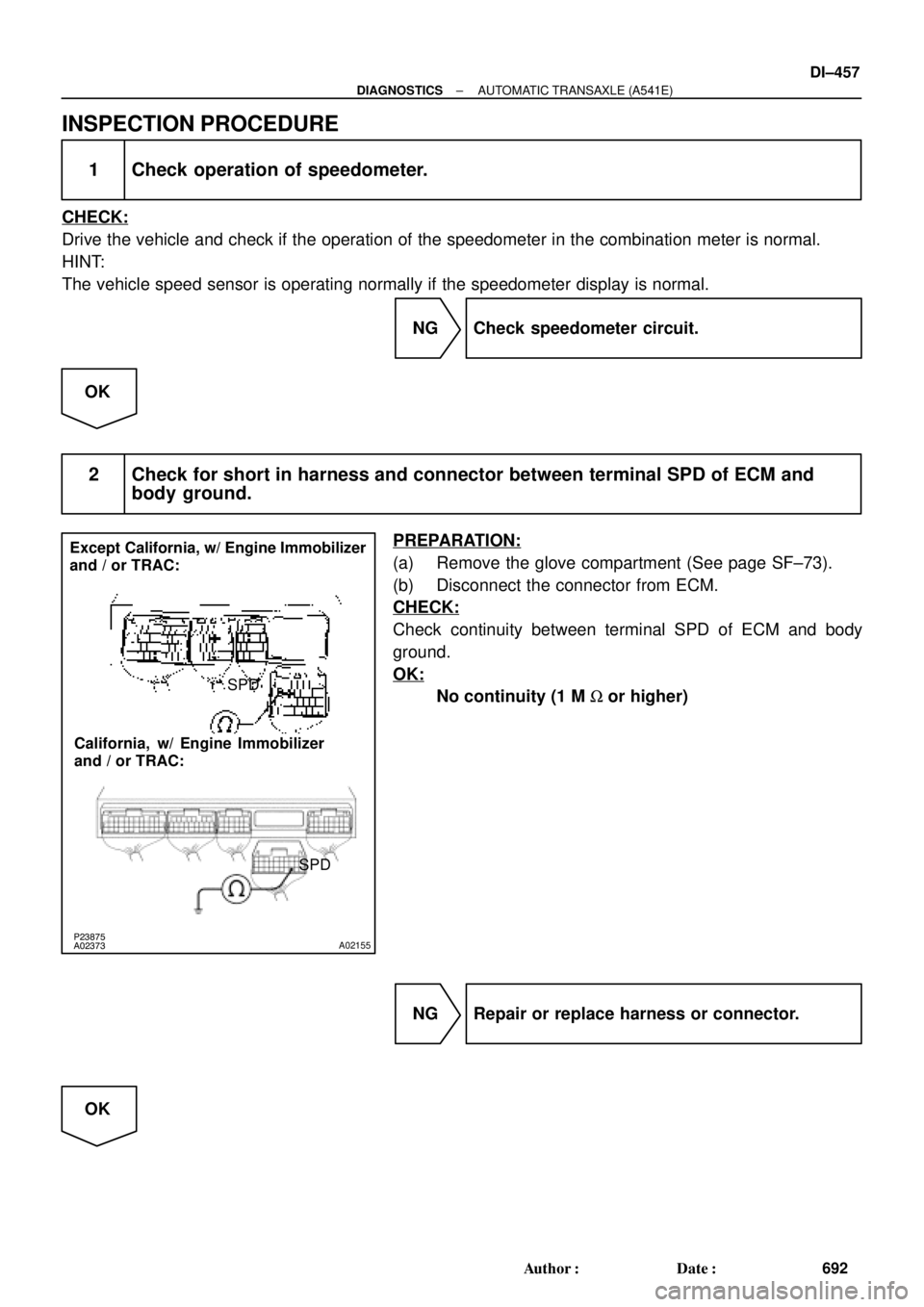
2 Check for short in harness and connector between terminal SPD of ECM and
body ground.
PREPARATION:
(a) Remove the glove compartment (See page SF±73).
(b) Disconnect the connector from ECM.
CHECK:
Check continuity between terminal SPD of ECM and body
ground.
OK:
No continuity (1 M W or higher)
NG Repair or replace harness or connector.
OK
Page 2878 of 4770
BE6653P23876D01908D02281
ON
SPD
(±)(+)
(±)
(+)
SPD Except California, w/ Engine
Immobilizer and / or TRAC:
California, w/ Engine Immobilizer
and / or TRAC:
DI±458
± DIAGNOSTICSAUTOMATIC TRANSAXLE (A541E)
693 Author�: Date�:
3 Check voltage between terminal SPD of ECM connector and body ground.
PREPARATION:
Turn ignition switch ON.
CHECK:
Measure voltage between terminal SPD of ECM connector and
body ground.
OK:
Voltage: 9 ~ 14 V
NG Check for open in harness and connector be-
tween junction connector (J15) and ECM (See
page IN±31).
OK
4 Check for open in harness and connector between junction connector (J15) and
combination meter (See page IN±31).
NG Repair or replace harness or connector.
OK
Page 2883 of 4770
D01092
Transaxle
*1: Except California, w/ Engine Immobilizer and / or TRAC
*2: California, w/ Engine Immobilizer and / or TRACShift Solenoid
Valve No.1
W3
6 E3
L±B BV
J/C J26
A*2 *1
Shift Solenoid
Valve No.2
E3A
AL±BE11
E10 7
11
817
E10
E11 *2 *1ECM
B+
S1
S2B+
Cruise Control ECU
Q07642D00833D01909
California, w/ Engine Immobilizer
and / or TRAC:S1
S2
S1
S2
Except California, w/ Engine Immobilizer
and / or TRAC:
± DIAGNOSTICSAUTOMATIC TRANSAXLE (A541E)
DI±463
698 Author�: Date�:
WIRING DIAGRAM
INSPECTION PROCEDURE
1 Measure resistance between terminal S1 or S2 of ECM and body ground.
PREPARATION:
Disconnect the connector from ECM.
CHECK:
Measure resistance between terminal S1 or S2 of ECM and
body ground.
OK:
Resistance: 11 ~ 15 W
Page 2884 of 4770
D00832Q02283
Q07935
D01910
S1 S2
S1 S2S1
S2 S1 S2 California, w/ Engine Immobilizer
and / or TRAC: Except California, w/ Engine Immobilizer
and / or TRAC:
DI±464
± DIAGNOSTICSAUTOMATIC TRANSAXLE (A541E)
699 Author�: Date�:
OK Check and replace the ECM.
NG
2 Check harness and connector between ECM and automatic transaxle solenoid
connector.
PREPARATION:
Disconnect the solenoid connector from the automatic trans-
axle.
CHECK:
Check the harness and connector between terminal S1 or S2
of ECM and terminal S1 or S2 of solenoid connector.
OK:
There is no open and no short circuit.
NG Repair or replace the harness or connector.
OK
Page 2888 of 4770

D01093
Transaxle
Shift Solenoid
Valve SL
2
E3P±L
E10B+
SLECM
*1: Except California, w/ Engine Immobilizer and / or TRAC
*2: California, w/ Engine Immobilizer and / or TRACE11 *2*1
27
9
Y DI±468
± DIAGNOSTICSAUTOMATIC TRANSAXLE (A541E)
703 Author�: Date�:
DTC P0773 Shift Solenoid E Electrical Malfunction
(Shift Solenoid Valve SL)
CIRCUIT DESCRIPTION
The shift solenoid valve SL is turned ON and OFF by signals from the ECM to control the hydraulic pressure
acting on the lock±up relay valve, which then controls operation of the lock±up clutch.
Fail safe function
If the ECM detects a malfunction, it turns the shift solenoid valve SL OFF.
DTC No.DTC Detecting ConditionTrouble Area
P0773
Either (a) or (b) are detected for 1 time.
(2 trip detection logic)
(a) Solenoid resistance is 8 W or less short circuit when sole-
noid is energized.
(b) Solenoid resistance is 100 kW or more open circuit when
solenoid is not energized.
�Open or short in shift solenoid valve SL circuit
�Shift solenoid valve SL
�ECM
WIRING DIAGRAM
DI02N±02
(+)
(±)
(+)
SPD Except California, w/ Engine
Immobilizer and / or TRAC:
California, w/ Engine Immobilizer
and / or TRAC:
DI±458
± DIAGNOSTICSAUTOMATIC TRANSAXL")

