Page 2904 of 4770
D01899
Cruise Control ECU
14
ODY±B7B+
OD1ECM
C15
E10E7
*1: Except California, w/ Engine Immobilizer and / or TRAC
*2: California, w/ Engine Immobilizer and / or TRAC*2
*1
24 DI±484
± DIAGNOSTICSAUTOMATIC TRANSAXLE (A541E)
719 Author�: Date�:
O/D Cancel Signal Circuit
CIRCUIT DESCRIPTION
While driving uphill with cruise control activated, in order to minimize gear shifting and provide smooth cruis-
ing overdrive may be prohibited temporarily under some condition.
The cruise control ECU sends O/D cut signals to the ECM as necessary and the ECM cancels overdrive
shifting until these signals are discontinued.
WIRING DIAGRAM
DI02S±02
Page 2905 of 4770
BE3840Q07659
D00053
D00835D01915
Except California, w/ Engine Immobilizer
and / or TRAC:
California, w/ Engine Immobilizer
and / or TRAC:OD1
OD1 ON
(+) (±) (±)
(+)
± DIAGNOSTICSAUTOMATIC TRANSAXLE (A541E)
DI±485
720 Author�: Date�:
INSPECTION PROCEDURE
1 Check voltage between terminal OD1 of ECM and body ground.
PREPARATION:
Turn the ignition switch ON.
CHECK:
Measure voltage between terminal OD1 of ECM and body
ground.
OK:
Voltage: 10 ~ 14 V
OK Proceed to next circuit inspection shown on
matrix chart (See page DI±453).
NG
Page 2907 of 4770
D01900
ECM
4E7OD2B+
G±O
IG1 C
CC
O2 O/D Main
Switch O/D Indicator
Light
C8 712
R±L
D
Ignition Switch
11K2
1DGAUGE J/C J4
G±OG±O
IG3
J/C J6
G±O
O2
B±Y
AM11B 1K
C10
AM1
F9 D
R±L
I16 W 21
24
I16 2
12
B±R
B±R
B±R1
2
F9Fusible Link Block
FL Main
Battery 1
F4B±GW±B
A
J/C J5
IF A
W±B
Left Kick Panel
*1: Except California, w/ Engine Immobilizer and / or TRAC
*2: California, w/ Engine Immobilizer and / or TRACInstrument Panel J/B
Instrument Panel J/B11106 *2*1
ALTE8
± DIAGNOSTICSAUTOMATIC TRANSAXLE (A541E)
DI±487
722 Author�: Date�:
O/D Main Switch & O/D OFF Indictor Light Circuit
CIRCUIT DESCRIPTION
The O/D main switch contacts go open when the switch is pushed in and go closed when it is pushed out.
In O/D main switch at OFF position, the O/D OFF indicator light lights up, and the ECM prohibits shifting over-
drive.
WIRING DIAGRAM
DI1KD±01
Page 2909 of 4770
BE3840
D00837Q07662D01916
Except California, w/ Engine Immobilizer
and / or TRAC:
California, w/ Engine Immobilizer
and / or TRAC:
OD2 OD2
(+) (±) ON
(+) (±)
± DIAGNOSTICSAUTOMATIC TRANSAXLE (A541E)
DI±489
724 Author�: Date�:
When not using TOYOTA hand±held tester
PREPARATION:
Turn the ignition switch ON.
CHECK:
Check voltage between terminal OD2 of ECM and body ground.
OK:
O/D main switchVoltage
OFFBelow 1 V
ON10 ~ 14 V
NG Check and replace the ECM.
NG
4 Check harness and connector between O/D OFF indicator light and ECM
(See page IN±31).
NG Repair or replace the harness or connector.
OK
Check and replace the ECM.
Page 4087 of 4770

SF0EA±03
S05545
DisconnectOhmmeter
E2
VC
A03009B01912
w/o Immobilizer
w/ ImmobiliserDisconnect
Vacuum
PIM
E2 ECM
ECM PIM (+)E2 (±) Voltmeter
Voltage Drop:
Applied
Vacuum
kPa
mmHg
in.Hg
Vo l t a ge
drop V13.3
100
3.94
0.3 ± 0.5
26.7 40.0 53.5 66.7
200
7.87
300
11.81400
15.75500
19.69
0.7 ± 0.9 1.1 ± 1.3 1.5 ± 1.7 1.9 ± 2.1
± SFI (5S±FE)MANIFOLD ABSOLUTE PRESSURE (MAP) SENSOR
SF±53
1486 Author�: Date�:
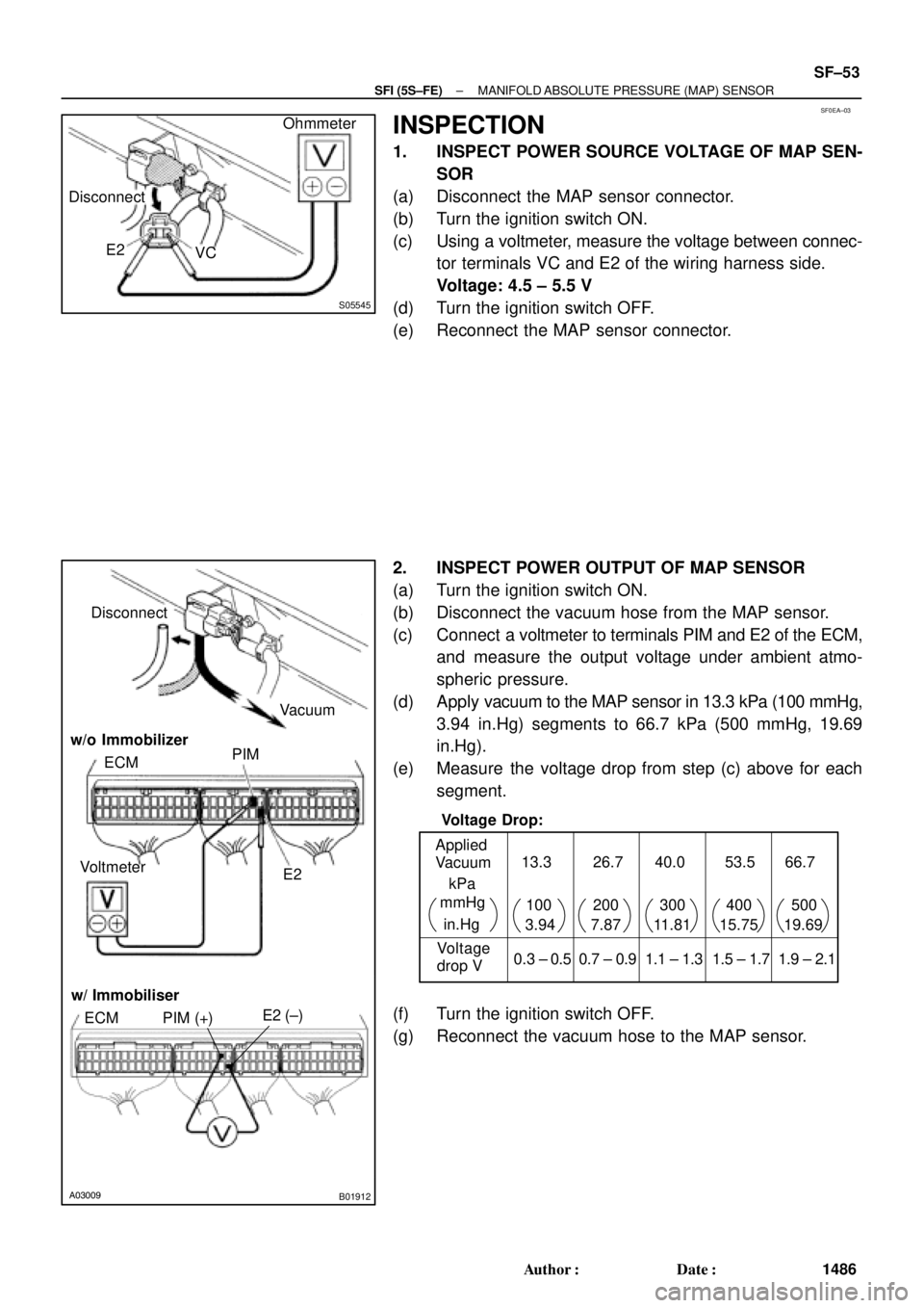
INSPECTION
1. INSPECT POWER SOURCE VOLTAGE OF MAP SEN-
SOR
(a) Disconnect the MAP sensor connector.
(b) Turn the ignition switch ON.
(c) Using a voltmeter, measure the voltage between connec-
tor terminals VC and E2 of the wiring harness side.
Voltage: 4.5 ± 5.5 V
(d) Turn the ignition switch OFF.
(e) Reconnect the MAP sensor connector.
2. INSPECT POWER OUTPUT OF MAP SENSOR
(a) Turn the ignition switch ON.
(b) Disconnect the vacuum hose from the MAP sensor.
(c) Connect a voltmeter to terminals PIM and E2 of the ECM,
and measure the output voltage under ambient atmo-
spheric pressure.
(d) Apply vacuum to the MAP sensor in 13.3 kPa (100 mmHg,
3.94 in.Hg) segments to 66.7 kPa (500 mmHg, 19.69
in.Hg).
(e) Measure the voltage drop from step (c) above for each
segment.
(f) Turn the ignition switch OFF.
(g) Reconnect the vacuum hose to the MAP sensor.
Page 4558 of 4770

Toyota Supports ASE CertificationPage 1 of 2
EG004-01Title:
M.I.L. ON" P1133
Models:
'97±'99 Camry and '99 Solara
Technical Service
BULLETIN
April 20, 2001
Under certain driving conditions, some 1997 ± 1999 5S±FE California emission
specification Camrys and 1999 5S±FE California emission specification Solaras may
exhibit a M.I.L. ªONº with DTC P1133 (Air Fuel Ratio Sensor Slow Response
Malfunction). An improved Air Fuel Ratio (A/F) Sensor was developed to correct this
condition (See TSB EG006±99).
In some rare cases, P1133 may still set after the improved A/F sensor is installed. The
Engine Control Module (ECM) logic has been modified to correct this condition.
�1997 ± 1999 model year Camrys with 5S±FE California emission specification.
�1999 model year Solaras with 5S±FE California emission specification.
PREVIOUS PART NUMBERCURRENT PART NUMBERPART NAME
89661±3T45189661±3T452ECM, 1999 AT
89661±0668189661±06682
,
ECM, 1999 MT
89661±3T27189661±3T272
,
ECM, 1998 ATNon Immobilizer89661±0650189661±06502
,
ECM, 1998 MTNon±Immobilizer
89661±3T04189661±3T042
,
ECM, 1997 AT
89661±0637189661±06372ECM, 1997 MT
89661±3T47189661±3T472ECM, 1999 ATImmobilizer89661±3T29189661±3T292ECM, 1998 ATImmobilizer
OP CODEDESCRIPTIONTIMEOPNT1T2
895011
Varied Work Code ªNº.R & R ECM For DOHC0.4See Previous PN
Above9999
Applicable Warranty*:
This repair is covered under the Toyota Federal Emissions Warranty. This warranty is
in effect for 96 months or 80,000 miles, whichever occurs first, from the vehicle's
in-service date.
* Warranty application is limited to correction of a problem based upon a customer's specific complaint.
ENGINE
Introduction
Applicable
Vehicles
Parts
Information
Warranty
Information
Page 4587 of 4770

Toyota Supports ASE CertificationPage 1 of 1
EL006±99Title:
ENGINE IMMOBILIZER SYSTEM
PRECAUTIONS
Models:
All Models
Technical Service
BULLETIN
October 8, 1999
REVISION NOTICE:
The information contained in this TSB updates EL001±98 dated January 23, 1998.
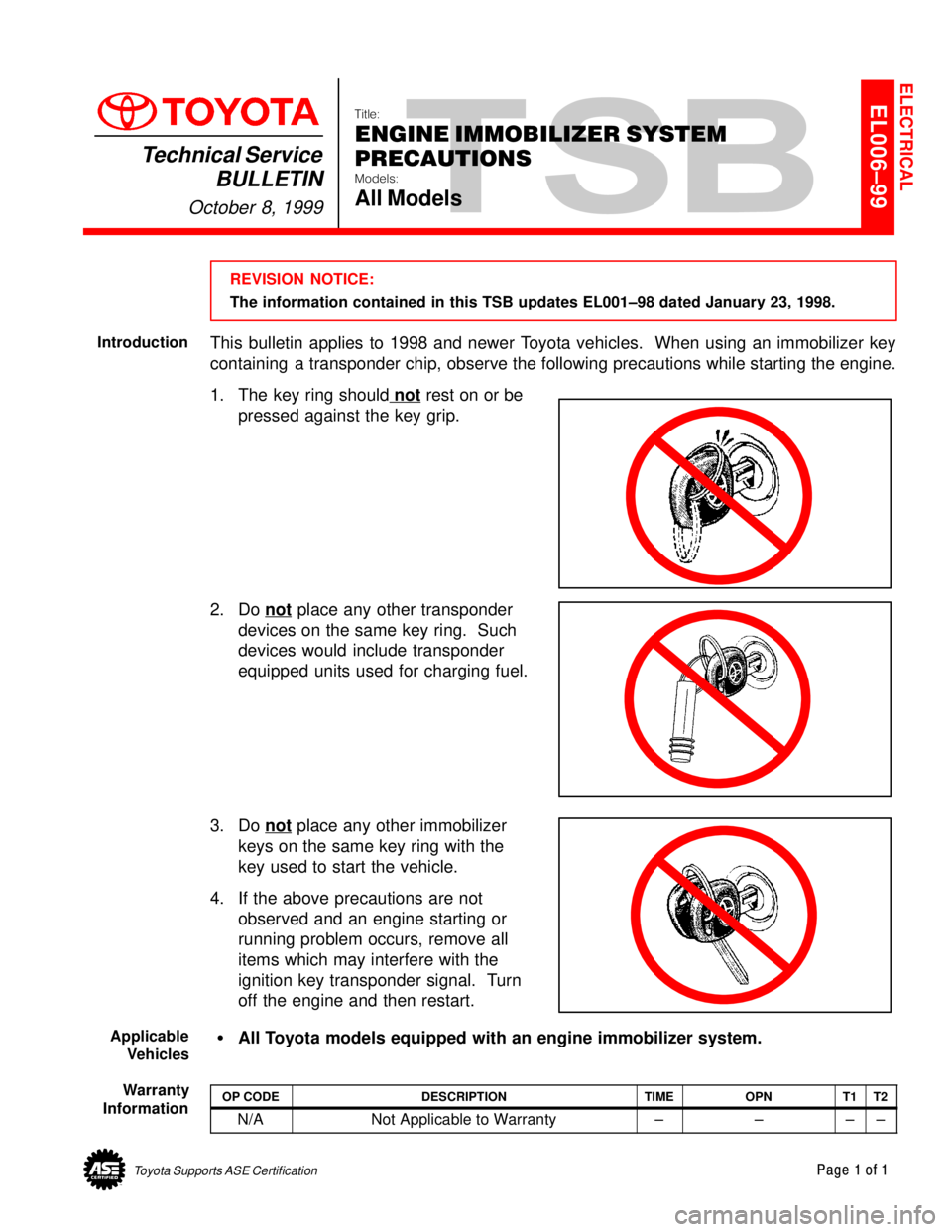
This bulletin applies to 1998 and newer Toyota vehicles. When using an immobilizer key
containing a transponder chip, observe the following precautions while starting the engine.
1. The key ring should not
rest on or be
pressed against the key grip.
2. Do not
place any other transponder
devices on the same key ring. Such
devices would include transponder
equipped units used for charging fuel.
3. Do not
place any other immobilizer
keys on the same key ring with the
key used to start the vehicle.
4. If the above precautions are not
observed and an engine starting or
running problem occurs, remove all
items which may interfere with the
ignition key transponder signal. Turn
off the engine and then restart.
�All Toyota models equipped with an engine immobilizer system.
OP CODEDESCRIPTIONTIMEOPNT1T2
N/ANot Applicable to Warranty±±±±
ELECTRICAL
Introduction
Applicable
Vehicles
Warranty
Information
Page 4663 of 4770

Toyota Supports ASE CertificationPage 1 of 9
SS001±99Title:
SCANTOOL IMMOBILIZER KEY CODE
UTILITY
Models:
'98 & '99 Avalon, Camry, Land Cruiser & Sienna
'99 Solara & 4Runner
Technical Service
BULLETIN
April 9, 1999
The Diagnostic Tester now incorporates a Key Code Utility Menu capable of performing
the following tasks for immobilizer functions:
�Key Code Registration
�Key Code Erasure
�Auto±Registration Closure
The information contained in this bulletin will provide you with a detailed outline for the
use of immobilizer functions with the Diagnostic Tester.
�1998 Avalon, Camry, Land Cruiser and Sienna.
�1998 Avalon, Camry, Land Cruiser, Sienna, Solara and 4Runner.
PART NUMBERPART NAME
01001271Toyota Diagnostic Tester Kit
01001895±0056.0a Diagnostic Software Card
NOTE:
Replacement Diagnostic Tester Kits or Software Cards may be ordered by calling
OTC at 1±800±933±8335.
Key Registration
This function allows the registration of additional key codes for transponder keys
(Master/Sub Keys) using a Registered Master Key.
Key Code Erasure
This function allows the user to erase all the key codes for transponder keys except
the Registered Master Key used during this function.
Auto Registration Closure
This function allows the user to close ªAuto Registration Modeª when less than three
keys have been registered.
NOTE:
When a new ECU is installed, it is in the ªAuto Registration Modeº from the factory.
This allows Transponder Keys to automatically register as they are inserted into the
Ignition Cylinder. After three Transponder Keys are registered, the ECU closes ªAuto
Registration Modeº. See the Repair Manual for further details.
OP CODEDESCRIPTIONTIMEOPNT1T2
N/ANot Applicable to Warranty ±±±±
SPECIAL SERVICE TOOLS
Introduction
Affected
Vehicles
Parts
Information
Function
Description
(Key Code
Utility)
Warranty
Information