Page 2889 of 4770
Q07648D00839D01911
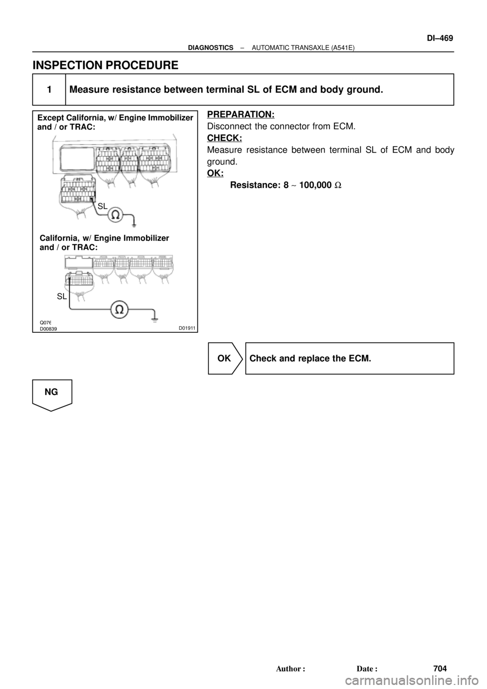
Except California, w/ Engine Immobilizer
and / or TRAC:
California, w/ Engine Immobilizer
and / or TRAC:SL
SL
± DIAGNOSTICSAUTOMATIC TRANSAXLE (A541E)
DI±469
704 Author�: Date�:
INSPECTION PROCEDURE
1 Measure resistance between terminal SL of ECM and body ground.
PREPARATION:
Disconnect the connector from ECM.
CHECK:
Measure resistance between terminal SL of ECM and body
ground.
OK:
Resistance: 8 ~ 100,000 W
OK Check and replace the ECM.
NG
Page 2890 of 4770
Q07938D00840D01912
SL
SL
SL
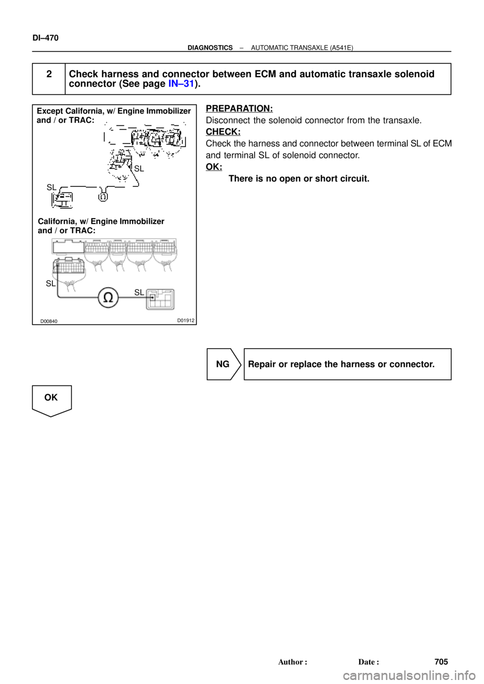
SL Except California, w/ Engine Immobilizer
and / or TRAC:
California, w/ Engine Immobilizer
and / or TRAC:
DI±470
± DIAGNOSTICSAUTOMATIC TRANSAXLE (A541E)
705 Author�: Date�:
2 Check harness and connector between ECM and automatic transaxle solenoid
connector (See page IN±31).
PREPARATION:
Disconnect the solenoid connector from the transaxle.
CHECK:
Check the harness and connector between terminal SL of ECM
and terminal SL of solenoid connector.
OK:
There is no open or short circuit.
NG Repair or replace the harness or connector.
OK
Page 2893 of 4770

Q04869
NC2 Revolution Sensor
D01094
Direct Clutch
Speed Sensor 2V3
1
V3
G R
E99
E94ECM
NC2
+
NC2±4 ~ 6 V
*1: Except California, w/ Engine Immobilizer and / or TRAC
*2: California, w/ Engine Immobilizer and / or TRAC*2 *1
E1114
26 *2 *1
E11
± DIAGNOSTICSAUTOMATIC TRANSAXLE (A541E)
DI±473
708 Author�: Date�:
DTC P1705 NC2 Revolution Sensor Circuit Malfunction
(Direct Clutch Speed Sensor)
CIRCUIT DESCRIPTION
This sensor detects the rotation speed of the direct clutch drum.
By comparing the direct clutch speed signal and the vehicle
speed sensor signal, the ECM detects the shift timing of the
gears and appropriately controls the engine torque and hydrau-
lic pressure in response to various conditions, thus performing
smooth gear shifting.
DTC No.DTC Detecting ConditionTrouble Area
P1705
The ECM detects conditions (a), (b), (c), (d), (e) and (f) conti-
nuity for 4 sec or more.
(2 trip detection logic)
(a) Vehicle speed : 32 km/h (20 mph) or more
(b) 3rd or 4th gear
(c) NC2 < 300 rpm
(d) Park/neutral position switch: OFF
(e) Solenoid valves and vehicle speed sensor are normal
(f) L position: OFF
�Open or short in direct clutch speed sensor circuit
�Direct clutch speed sensor
�ECM
WIRING DIAGRAM
DI02P±02
Page 2894 of 4770
Q07936D00834D01913
NC2+NC2±
NC2+
NC2±
Except California, w/ Engine Immobilizer
and / or TRAC:
California, w/ Engine Immobilizer
and / or TRAC:
DI±474
± DIAGNOSTICSAUTOMATIC TRANSAXLE (A541E)
709 Author�: Date�:
INSPECTION PROCEDURE
1 Check resistance between terminals NC2+ and NC2± of ECM.
PREPARATION:
Disconnect the connector from ECM.
CHECK:
Check resistance between terminals NC2+ and NC2± of ECM.
OK:
Resistance: 560 ~ 680 W
OK Check and replace the ECM.
NG
Page 2897 of 4770
D01095
Shift Solenoid
Valve SLN 1
4
B±YW±L3
2
SLN
±
SLN+
ECM
*1: Except California, w/ Engine Immobilizer and / or TRAC
*2: California, w/ Engine Immobilizer and / or TRAC*2 *1
E11
E3E10
E9 E3*2 *1
1920
R
L
E11
D00050
2
1
21
± DIAGNOSTICSAUTOMATIC TRANSAXLE (A541E)
DI±477
712 Author�: Date�:
WIRING DIAGRAM
INSPECTION PROCEDURE
1 Check shift solenoid valve SLN.
PREPARATION:
Disconnect the shift solenoid valve SLN connector.
CHECK:
(a) Measure resistance between terminals 1 and 2 of sole-
noid connector.
(b) Connect positive � lead with an 8 ~10 W bulb to terminal
1 of solenoid connector and negative ��lead to terminal
2, then check the movement of the valve.
OK:
(a) Resistance: 5.1 ~ 5.5 W
(b)
When battery positive voltage is applied.Valve move in direction in illustration.
(on the left)
When battery positive voltage is cut off.Valve move in direction in illustration.
(on the right)
Page 2900 of 4770

D01897
Combination Meter
Ignition Switch Except California, w/ Engine Immobilizer and / or TRAC:
R
2
L8
11
6 C8
13
165
R±B
L±W YIJ1
IG310
1H
1VECM
1
E7
B+ 4
II2 P1
II3D J/C J2910 C8
C8O
Y
R±BY
R 2L
E7
E7
E10 II2 P1
P1
P1D D
J/C J29 E
15
14
B±W A
GR3
6CL±W (*1, *3)
O (*2, *4) LL
2L
RL R±L
J27J28
J/C
10FE E Y
Y
L±W L±W6 5
8
R±BR±BR±B
5
P1 P12
AJ/C
J24
R±LA J27
C
B±W
B
BB
J/C J26
B±W
II2II22
R±L
J28J/C J28
F
J2811
II2
B±WBBJ/C J29NSW
R±L
B±W 1
1
GAUGE
1K 1J I16 I16
I16 I16
1J 1K3
4 Starter B±Y
R 4
8 2
7IG1
AM1
ST2
AM2 1B
2L 2AW
W±R 2
1K AM1
2 1 1
1B 1K5 5
GR (*4)
B±O (*5)
W±R
41
AM2
B
B B±R
B±R
B±R
1
2 F9
F9
ALT
11F4
F6
B±G
BatteryB
C
J8J7GR (*4)
B±O (*5)3
1
2535
2B
2D
2J
2K 11
12
ST
Relay
B±R
Starter
W±BAJ/C J11
IG
Left Kick
Panel Park/Neutral Position Switch
9
J/C CInstrument Panel J/B
Fusible
Link BlockEngine Room J/B No.2
MAIN 3
FL
Main
*1: w/ Engine Immobilizer System
*2: w/o Engine Immobilizer System
*3: TMC Made Ex. USA w/ TRAC
*4: TMMK Made, TMC Made USA w/ TRAC DI±480
± DIAGNOSTICSAUTOMATIC TRANSAXLE (A541E)
715 Author�: Date�:
WIRING DIAGRAM
Page 2901 of 4770

D01898
Combination Meter
Ignition Switch California, w/ Engine Immobilizer and / or TRAC:
R
2
L8
11
6 C8
13
165
R±B
L±W YIJ1
IG310
1H 1VECM
12
B+ 4
II2 P1
II3D J/C J29 C8
C8O
Y
R±BY
R 2 L
II2
P1
P1
P1D D
J/C J29 E
20
B±W A
GR3
6L±W (*1, *3)
O (*2, *4) LL
2L
RL R±L
J27J28
J/C
10FE E
Y Y
L±W L±W65
8
R±B
R±BR±B
5
P1P12
AJ/C
J24
R±LJ27
B±W
BB
II2II22
R±L
J28J/C J28
F
J28J/C J29NSW
R±L
B±W 1 1
GAUGE
1K1J
I16I16
I16 I16 1J1K3 4
Starter B±Y
R 4
8 2
7IG1
AM1
ST2
AM2 1B
2L 2AW
W±R 2
1K AM1
2 1 1
1B1K5 5
GR (*4)
B±O (*5)
W±R
41
AM2
B
B B±R
B±R
B±R
12
F9 F9
ALT
11
F4F6
B±G
FL
Main
BatteryF
J8
J7GR (*4)
B±O (*5)3
12535
2B
2D
2J2K 11
12
ST
Relay
B±R
Starter
W±BAJ/C J11
IG
Left Kick
Panel *1: w/ Engine Immobilizer System
*2: w/o Engine Immobilizer System
*3: TMC Made Ex. USA w/ TRAC
*4: TMMK Made, TMC Made USA w/ TRAC Park/Neutral Position SwitchE8
3
2
B±W B B
J/C J26II2 11
B±W
B
C9
J/C C
E8
E8E8
3C
CA
Engine Room J/B No.2
MAINInstrument Panel J/B
Instrument Panel J/B
Fusible
Link Block
± DIAGNOSTICSAUTOMATIC TRANSAXLE (A541E)
DI±481
716 Author�: Date�:
Page 2902 of 4770

BE3840D00052D00836D01914
Except California, w/ Engine Immobilizer
and / or TRAC:
California, w/ Engine Immobilizer
and / or TRAC:ON
L
NSW
2
R
2R
L
NSW
Position
P, N
R
D
2
LNSW±Body
groundR±Body
ground2±Body
groundL±Body
ground
0 V
0 V0 V0 V
0 V
0 V
0 V 0 V
0 V
0 V 0 V
0 V
0 V 9 ~ 14 V*
9 ~ 14 V
9 ~ 14 V
9 ~ 14 V9 ~ 14 V
9 ~ 14 V 9 ~ 14 V* DI±482
± DIAGNOSTICSAUTOMATIC TRANSAXLE (A541E)
717 Author�: Date�:
INSPECTION PROCEDURE
1 Read PNP, REVERSE, 2ND and LOW signals.
When using TOYOTA hand±held tester.
PREPARATION:
(a) Remove the DLC3 cover.
(b) Connect a TOYOTA hand±held tester to the DLC3.
(c) Turn the ignition switch ON and TOYOTA hand±held tes-
ter main switch ON.
CHECK:
Shift lever into the P, R, N, 2 and L positions, and read the PNP,
REVERSE, 2ND and LOW signals on the TOYOTA hand±held
tester.
OK:
Shift positionSignal
22ND OFF " ON
LLOW OFF " ON
RREVERSE OFF " ON
P, NNSW OFF " ON
When not using TOYOTA hand±held tester.
PREPARATION:
Turn the ignition switch ON.
CHECK:
Measure voltage between terminals NSW, 2, L and R of ECM
and body ground when the shift lever is shifted to the following
positions.
OK:
HINT:
*: The voltage will drop slightly due to lighting up of the back up
light.

709")
