Page 72 of 4770

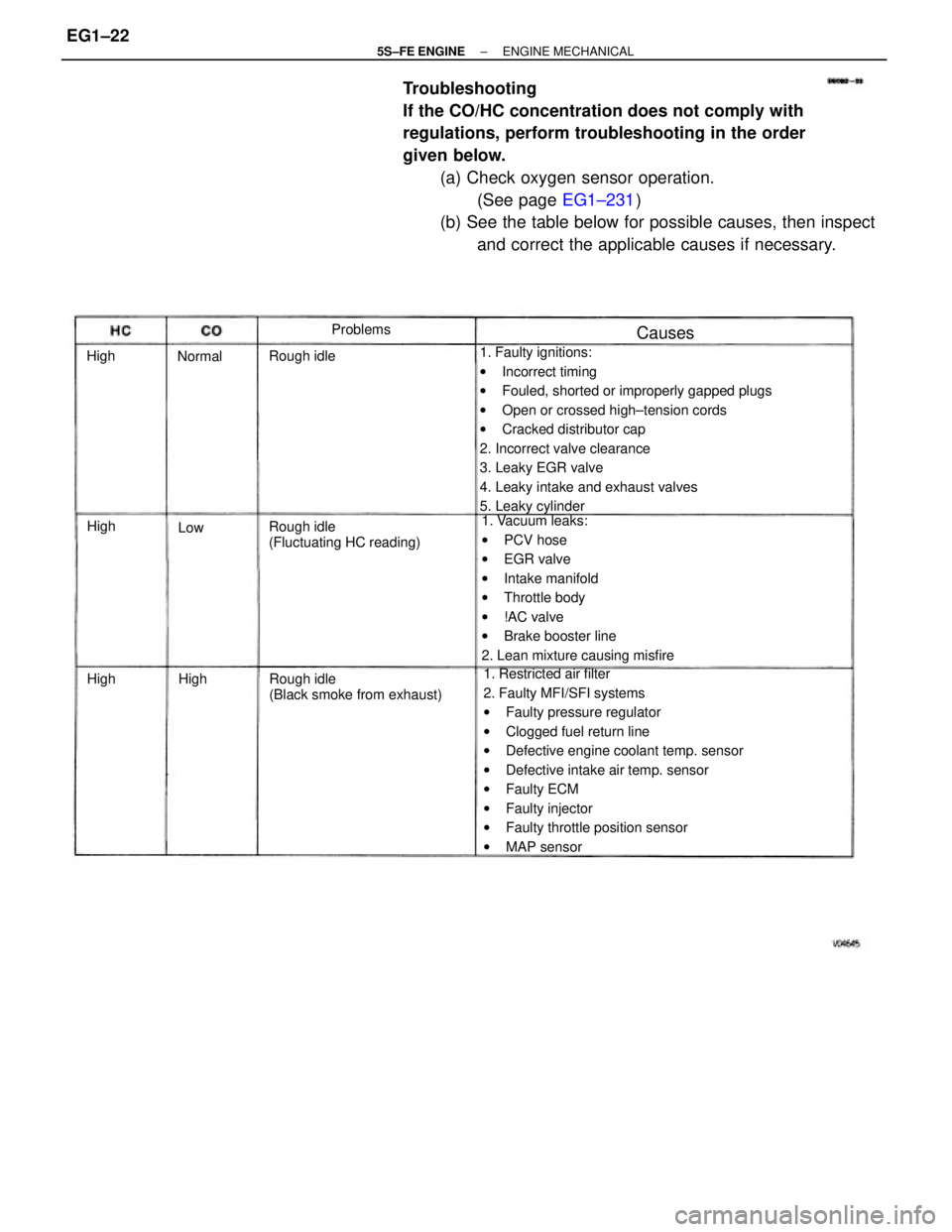
Troubleshooting
If the CO/HC concentration does not comply with
regulations, perform troubleshooting in the order
given below.
(a) Check oxygen sensor operation.
(See page EG1±231)
(b) See the table below for possible causes, then inspect
and correct the applicable causes if necessary.
1. Faulty ignitions:
wIncorrect timing
wFouled, shorted or improperly gapped plugs
wOpen or crossed high±tension cords
wCracked distributor cap
2. Incorrect valve clearance
3. Leaky EGR valve
4. Leaky intake and exhaust valves
5. Leaky cylinder
1. Restricted air filter
2. Faulty MFI/SFI systems
wFaulty pressure regulator
wClogged fuel return line
wDefective engine coolant temp. sensor
wDefective intake air temp. sensor
wFaulty ECM
wFaulty injector
wFaulty throttle position sensor
wMAP sensor 1. Vacuum leaks:
wPCV hose
wEGR valve
wIntake manifold
wThrottle body
w!AC valve
wBrake booster line
2. Lean mixture causing misfire
Rough idle
(Black smoke from exhaust) Rough idle
(Fluctuating HC reading) Rough idleProblems
Causes
Normal
High High High
HighLow
± 5S±FE ENGINEENGINE MECHANICALEG1±22
Page 96 of 4770
17. DISCONNECT VACUUM HOSES
Disconnect the following hoses:
(1) MAP sensor hose from air intake chamber
(2) Brake booster vacuum hose from air intake cha±
mber
(3) PS vacuum hose from air intake chamber
(4) Vacuum sensing hose from fuel pressure regula±
tor 1
S. W/ A/C:
DISCONNECT A/C IDLE±UP VALVE CONNECTOR
19. EXCEPT CALIFORNIA:
REMOVE AIR TUBE
(a) Disconnect the following hoses from the air tube:
(1) w/ A/C:
Air hose from ASV
(2) 2 air hoses from PS pump I6. REMOVE EGR VALVE AND VACUUM MODULATOR
(a) Disconnect the EGR gas temperature sensor connec±
tor.
(b) Disconnect the following hoses:
(1) 2 vacuum hoses from VSV (for EGR)
(2) Vacuum hose from charcoal canister
(c) Disconnect the vacuum hose clamp.
(d) Loosen the union nut of the EGR pipe, and remove the
2 nuts, EGR valve, vacuum modulator, vacuum hoses
assembly and gasket.
(b) Remove the 3 bolts, wire clamp and air tube.
± 5S±FE ENGINEENGINE MECHANICALEG1±46
Page 127 of 4770

25. INSTALL EGR VALVE AND VACUUM MODULATOR
(a) Install a new gasket and the EGR valve with the union
nut and 2 nuts.
Union nut:
Torque: 59 N±m (600 kgf±cm, 43 ft±lbf)
Nut:
Torque: 13 N±m (130 kgf±cm, 9 ft±lbf)
(b) Install the EGR modulator to the clamp. 23. CONNECT VACUUM HOSES
Connect the following hoses:
(1) MAP sensor hose to air intake chamber
(2) Brake booster vacuum hose to air intake chamber
(3) PS vacuum hose to air intake chamber
(4) Vacuum sensing hose to fuel pressure regulator.
24. w/ A/C:
CONNECT A/C IDLE±UP VALVE CONNECTOR(b) Connect the following hoses:
(1) w/ A/C:
A/C hose (from ASV) to air tube
(2) 2 air hoses (from PS pump) to air tube
(3) 2 vacuum hoses to VSV (for fuel pressure con±
trol)
(4) Vacuum hose to air intake chamber
22. EXCEPT CALIFORNIA:
INSTALL AIR TUBE
(a) Install the air tube and wire clamp with the 3 bolts.
(b) Connect the following hoses to the air tube:
(1) w/ A/C:
Air hose from ASV
(2) 2 air hose from PS pump
± 5S±FE ENGINEENGINE MECHANICALEG1±77
Page 136 of 4770
(c) Disconnect the following connectors:
(1) Igniter connector
(2) California only:
Ignition coil connector
(3) Noise filter connector
(4) 2 ground straps from LH fender apron
(5) Connector from LH fender apron 12. DISCONNECT WIRES AND CONNECTORS
(a) Remove the engine relay box, and disconnect the 5
connectors.
(b) Connector from LH fender apron
(6) Data link connector 1
(7) 2 ground straps from RH fender apron
(d) Disconnect the MAP sensor connector.
13. DISCONNECT HEATER HOSES
14. DISCONNECT FUEL RETURN HOSE
CAUTION: Catch leaking fuel in a container.
± 5S±FE ENGINEENGINE MECHANICALEG1±86
Page 137 of 4770
17. M/T:
REMOVE CLUTCH RELEASE CYLINDER WITHOUT
DISCONNECTING TUBE
Remove the 4 bolts, release cylinder and tube from
the transaxle.15. DISCONNECT FUEL INLET HOSE
CAUTION: Catch leaking fuel in a container.
16. M/T:
REMOVE STARTER
19. DISCONNECT VACUUM HOSES
(a) MAP sensor hose from air intake chamber
(b) Brake booster vacuum hose from air intake chamber 18. DISCONNECT TRANSAXLE CONTROL CABLE (S)
FROM TRANSAXLE
± 5S±FE ENGINEENGINE MECHANICALEG1±87
Page 181 of 4770
19. M/T:
INSTALL CLUTCH RELEASE CYLINDER
Install the release cylinder and tube with the 4 bolts.
20. M/T:
INSTALL STARTER17. CONNECT VACUUM HOSES
(a) MAP sensor hose to air intake chamber
(b) Brake booster vacuum hose to air intake chamber
18. CONNECT TRANSAXLE CONTROL CABLE
(S) TO TRANSAXLE (c) Charcoal canister vacuum hose
± 5S±FE ENGINEENGINE MECHANICALEG1±131
Page 183 of 4770

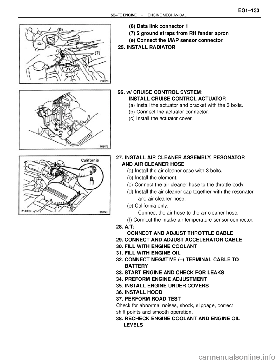
27. INSTALL AIR CLEANER ASSEMBLY, RESONATOR
AND AIR CLEANER HOSE
(a) Install the air cleaner case with 3 bolts.
(b) Install the element.
(c) Connect the air cleaner hose to the throttle body.
(d) Install the air cleaner cap together with the resonator
and air cleaner hose.
(e) California only:
Connect the air hose to the air cleaner hose.
(f) Connect the intake air temperature sensor connector.
28. A/T:
CONNECT AND ADJUST THROTTLE CABLE
29. CONNECT AND ADJUST ACCELERATOR CABLE
30. FILL WITH ENGINE COOLANT
31. FILL WITH ENGINE OIL
32. CONNECT NEGATIVE (±) TERMINAL CABLE TO
BATTERY
33. START ENGINE AND CHECK FOR LEAKS
34. PREFORM ENGINE ADJUSTMENT
35. INSTALL ENGINE UNDER COVERS
36. INSTALL HOOD
37. PERFORM ROAD TEST
Check for abnormal noises, shock, slippage, correct
shift points and smooth operation.
38. RECHECK ENGINE COOLANT AND ENGINE OIL
LEVELS26. w/ CRUISE CONTROL SYSTEM:
INSTALL CRUISE CONTROL ACTUATOR
(a) Install the actuator and bracket with the 3 bolts.
(b) Connect the actuator connector.
(c) Install the actuator cover.(6) Data link connector 1
(7) 2 ground straps from RH fender apron
(e) Connect the MAP sensor connector.
25. INSTALL RADIATOR
± 5S±FE ENGINEENGINE MECHANICALEG1±133
Page 243 of 4770

10. DISCONNECT VACUUM HOSES
Disconnect the following hoses:
(1) MAP sensor hose from air intake chamber
(2) Brake booster vacuum hose from air intake chamber
(3) Vacuum sensing hose from fuel pressure regulator
11. w/ A/C:
DISCONNECT A/C IDLE±UP VALVE CONNECTOR
12. DISCONNECT 2 ENGINE WIRE GROUND STRAPS
FROM INTAKE MANIFOLD
13. DISCONNECT KNOCK SENSOR AND VSV (FOR
EGR) CONNECTORS
14. CALIFORNIA ONLY:
DISCONNECT VSV (FOR FUEL PRESSURE CONTROL)
CONNECTOR AND VACUUM HOSES
15. REMOVE BOLT AND WIRE CLAMP, AND DISCON±
NECT ENGINE WIRE HARNESS 9. REMOVE EGR VALVE AND VACUUM MODULATOR
(a) Disconnect the EGR gas temperature sensor connec-
tor.
(b) Disconnect the following hoses:
(1) 2 vacuum hoses from VSV (for EGR)
(2) Vacuum hose from charcoal canister
(c) Disconnect the vacuum hose clamp.
16. REMOVE INTAKE MANIFOLD
(a) Remove the 4 bolts, wire bracket, No.1 air intake
chamber and manifold stays. (d) Loosen the union nut of the EGR pipe, and remove the
2 nuts, the EGR valve, vacuum modulator, vacuum
hoses assembly and gasket.
± 5S±FE ENGINEMFI/SFI SYSTEMEG1±193