Page 3981 of 4770

SS±19
182 Author�: Date�:
SFI (5S±FE)
SERVICE DATA
Fuel pressure
regulatorFuel pressure at no vacuum301 ± 347 kPa (3.1 ± 3.5 kgf/cm2, 44 ± 50 psi)")
SS0AG±03
± SERVICE SPECIFICATIONSSFI (5S±FE)
SS±19
182 Author�: Date�:
SFI (5S±FE)
SERVICE DATA
Fuel pressure
regulatorFuel pressure at no vacuum301 ± 347 kPa (3.1 ± 3.5 kgf/cm2, 44 ± 50 psi)
Fuel pumpResistance at 20°C (68°F)0.2 ± 3.0 W
InjectorResistance at 20°C (68°F)
Injection volume
Difference between each cylinder
Fuel leakage13.4 ± 14.2 W
54 ± 69 cm3 (3.3 ± 4.2 cu in.) per 15 seconds
7 cm3 (0.4 cu in.) or less
One drop or less per minute
Throttle bodyThrottle body fully closed angle
Throttle opener setting speed6°
1,300 ± 1,500 rpm (w/ Cooling fan OFF)
Throttle
position
sensorClearance between stop screw and lever
0 mm (0 in.) VTA ± E2
Throttle valve fully open VTA ± E2
± VC ± E2
0.2 ± 5.7 kW
2.0 ± 10.2 kW
2.5 ± 5.9 kW
IAC valveResistance (+B ± ISCC or ISCO) at cold
at hot17.0 ± 24.5 W
21.5 ± 28.5 W
VSV for EVAPResistance at 20°C (68°F)30 ± 34 W
VSV for vapor
pressure
sensorResistance at 20°C (68°F)33 ± 39 W
VSV for EGRResistance at 20°C (68°F)33 ± 39 W
ECT sensorResistance at ±20°C (±4°F)
at 0°C (32°F)
at 20°C (68°F)
at 40°C (104°F)
at 60°C (140°F)
at 80°C (176°F)10 ± 20 kW
4 ± 7 kW
2 ± 3 kW
0.9 ± 1.3 kW
0.4 ± 0.7 kW
0.2 ± 0.4 kW
IAT sensorResistance at ±20°C (±4°F)
at 0°C (32°F)
at 20°C (68°F)
at 40°C (104°F)
at 60°C (140°F)
at 80°C (176°F)10 ± 20 kW
4 ± 7 kW
2 ± 3 kW
0.9 ± 1.3 kW
0.4 ± 0.7 kW
0.2 ± 0.4 kW
MAP sensorPower source voltage4.5 ± 5.5 V
Vapor Pressure
SensorPower sorce voltage4.5 ± 5.5 V
A/F sensorResistance at 20°C (68°F)0.8 ± 1.4 W
Heated oxygen
sensorResistance at 20°C (68°F)11 ± 16 W
Fuel cut rpmFuel return rpm1,500 rpm
Page 4086 of 4770
SF0E9±03
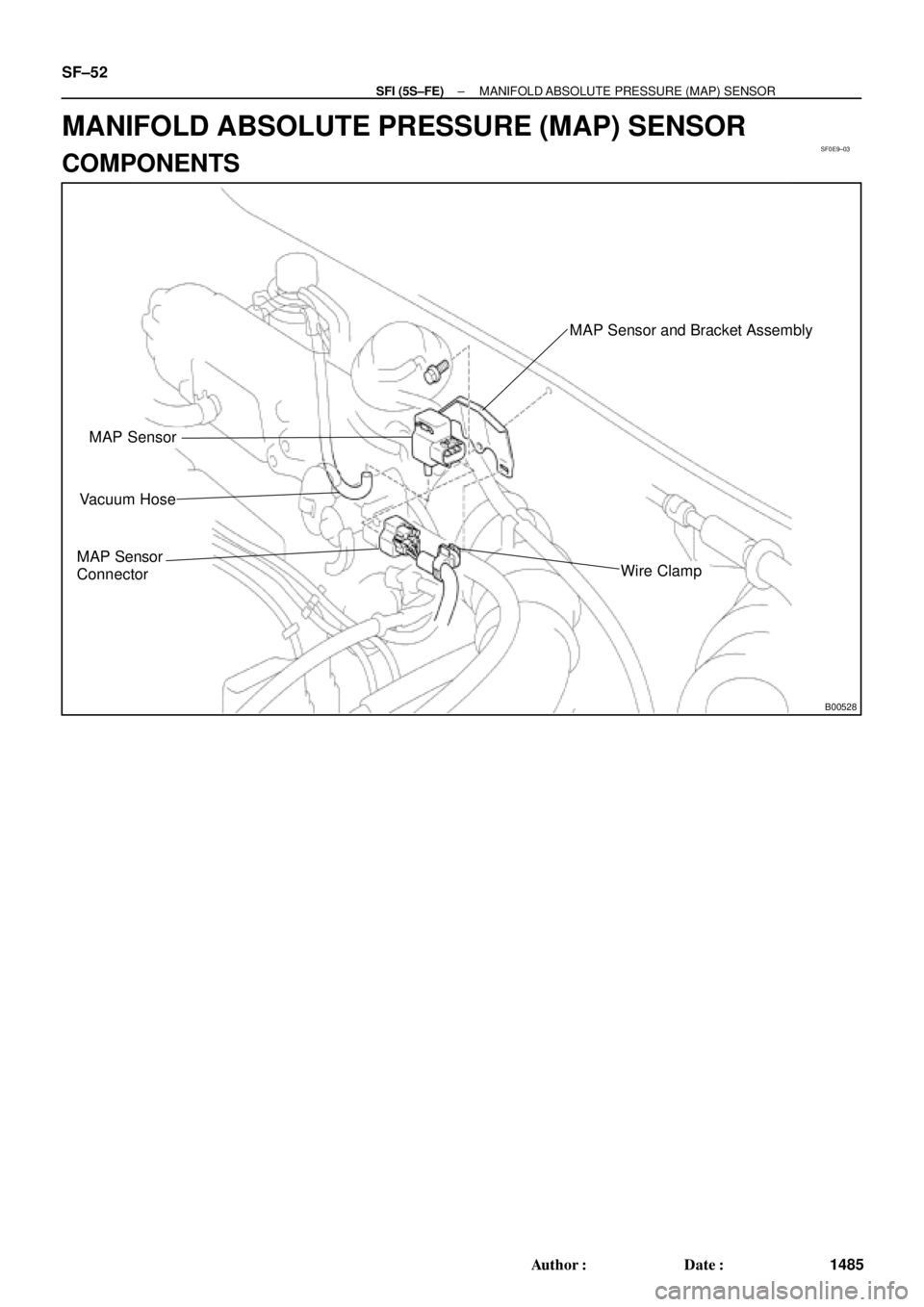
B00528
MAP Sensor
Vacuum Hose
MAP Sensor
Connector
MAP Sensor and Bracket Assembly
Wire Clamp
SF±52
± SFI (5S±FE)MANIFOLD ABSOLUTE PRESSURE (MAP) SENSOR
1485 Author�: Date�:
MANIFOLD ABSOLUTE PRESSURE (MAP) SENSOR
COMPONENTS
Page 4087 of 4770
E2 (±) Voltmeter
Voltage Drop:
Applied
Vacuum
kPa
mmHg
in.Hg
Vo l t a ge
d")
SF0EA±03
S05545
DisconnectOhmmeter
E2
VC
A03009B01912
w/o Immobilizer
w/ ImmobiliserDisconnect
Vacuum
PIM
E2 ECM
ECM PIM (+)E2 (±) Voltmeter
Voltage Drop:
Applied
Vacuum
kPa
mmHg
in.Hg
Vo l t a ge
drop V13.3
100
3.94
0.3 ± 0.5
26.7 40.0 53.5 66.7
200
7.87
300
11.81400
15.75500
19.69
0.7 ± 0.9 1.1 ± 1.3 1.5 ± 1.7 1.9 ± 2.1
± SFI (5S±FE)MANIFOLD ABSOLUTE PRESSURE (MAP) SENSOR
SF±53
1486 Author�: Date�:
INSPECTION
1. INSPECT POWER SOURCE VOLTAGE OF MAP SEN-
SOR
(a) Disconnect the MAP sensor connector.
(b) Turn the ignition switch ON.
(c) Using a voltmeter, measure the voltage between connec-
tor terminals VC and E2 of the wiring harness side.
Voltage: 4.5 ± 5.5 V
(d) Turn the ignition switch OFF.
(e) Reconnect the MAP sensor connector.
2. INSPECT POWER OUTPUT OF MAP SENSOR
(a) Turn the ignition switch ON.
(b) Disconnect the vacuum hose from the MAP sensor.
(c) Connect a voltmeter to terminals PIM and E2 of the ECM,
and measure the output voltage under ambient atmo-
spheric pressure.
(d) Apply vacuum to the MAP sensor in 13.3 kPa (100 mmHg,
3.94 in.Hg) segments to 66.7 kPa (500 mmHg, 19.69
in.Hg).
(e) Measure the voltage drop from step (c) above for each
segment.
(f) Turn the ignition switch OFF.
(g) Reconnect the vacuum hose to the MAP sensor.
Page 4179 of 4770
H08316
Side Airbag Assembly (LH)
(Squib) Side Airbag Sensor (LH)Side Airbag Sensor (RH) Side Airbag Assembly (RH)
(Squib)
Seat Belt
Pretensioner (RH)
Airbag Sensor
AssemblyFront Passenger Airbag Assembly (Squib)
Spiral Cable
No.1 J/B 2
37 8
10
11
12
13
1
4
5
6
9
Steering Wheel
Pad (Squib) Front Airbag Sensor (RH)
Front Airbag Sensor (LH)
Seat Belt
Pretensioner (LH) 14
15
16
RS±4
± SUPPLEMENTAL RESTRAINT SYSTEMSRS AIRBAG
2149 Author�: Date�:
10. TMC made:
SRS CONNECTORS
No.ItemApplication
(1)Terminal Twin±Lock MechanismConnectors 1, 2, 3, 4, 5, 6, 7, 8, 9, 10, 11, 12, 13, 14, 15, 16
(2)Airbag Activation Prevention MechanismConnectors 1, 2, 3, 4, 5, 7, 8, 9, 15, 16
(3)Electrical Connection Check MechanismConnectors 1, 2, 3
(4)Connector Twin±Lock MechanismConnectors 5, 6, 7
Page 4180 of 4770
H08247
Airbag Sensor
Assembly2
31
Side Airbag Assembly (RH)
(Squib)
Seat Belt
Pretensioner (RH)
Side Airbag Sensor (RH)
Front Passenger Airbag
Assembly (Squib)
Spiral Cable
Steering Wheel
Pad (Squib)
No.1 J / B
Side Airbag Sensor (LH)
Side Airbag Assembly (LH)
(Squib)
4
5
6
7
14
9
10
1112
13
8
15
Seat Belt
Pretensioner (LH)
16
17
18
Front Airbag Sensor (RH)
Front Airbag Sensor (LH)
± SUPPLEMENTAL RESTRAINT SYSTEMSRS AIRBAG
RS±5
2150 Author�: Date�:
11. TMMK made:
SRS CONNECTORS
No.ItemApplication
(1)Terminal Twin±Lock MechanismConnectors 1, 2, 3, 4, 5, 6, 7, 8, 9, 10, 11, 12, 13, 14, 15, 16,
17, 18
(2)Airbag Activation Prevention MechanismConnectors 1, 2, 3, 4, 5, 7, 8, 9, 15, 16, 17, 18
(3)Electrical Connection Check MechanismConnectors 1, 2, 3
(4)Connector Twin±Lock MechanismConnectors 5, 6, 7

(Squib) Side Airbag Sensor (LH)Side Airbag Sensor (RH) Side Airbag Assembly (RH)
(Squib)
Seat Belt
Pretensioner (RH)
Airbag Sensor
AssemblyFront Passenger Airbag Assem")

(Squib)
Seat Belt
Pretensioner (RH)
Side Airbag Sensor (RH)
Front Passenger Airbag
Assembly (Squib)
Spiral Cable
Steering Wheel
Pad (Squib)")