Page 3394 of 4770
CO/HC
1174 Author�: Date�:
If the CO/HC concentration does not comply with regulations,
troubleshoot in the order given below.
(1) Check oxygen sensor operation.
(Se")
EM±2
± ENGINE MECHANICAL (5S±FE)CO/HC
1174 Author�: Date�:
If the CO/HC concentration does not comply with regulations,
troubleshoot in the order given below.
(1) Check oxygen sensor operation.
(See page DI±66)
(2) See the table below for possible causes, then in-
spect and correct the applicable causes if neces-
sary.
COHCSymptomCauses
NormalHighRough idle1. Faulty ignitions:
� Incorrect timing
� Fouled, shorted or improperly gapped plugs
� Open or crossed hi
gh±tension cords� Oen or crossed high±tension cords
2. Incorrect valve clearance
3. Leaky EGR valve
4. Leaky intake and exhaust valves
5. Leaky cylinder
LowHighRough idle
(Fluctuating HC reading)1. Vacuum leaks:
� PCV hose
� EGR valve
� Intake manifold
� Throttle body
� IAC valve
� Brake booster line
2. Lean mixture causing misfire
HighHighRough idle
(Black smoke from exhaust)1. Restricted air filter
2. Faulty SFI system
� Faulty pressure regulator
� Defective ECT sensor
� Defective IAT sensor
� Faulty ECM
� Faulty injector
� Faulty throttle position sensor
� MAP sensor
Page 3423 of 4770
A07358
Ground Wire
MAP Sensor
Vacuum Hose
Brake Booster
Vacuum Hose
Intake
Manifold
Air Hose for Air Assist System (California)
Intake Manifold
Stay
Injector
(Except California)
Knock Sensor 1
ConnectorPCV HoseVSV Connector
for EGR
VSV for EGREGR Valve and Vacuum
Modulator
Fuel Inlet Hose
Fuel Pulsation Damper
� O±Ring
Injector
(California)Injector
Connector Spacer
Insulator
N´m (kgf´cm, ft´lbf)
� Non±reusable part
� Gasket
� Insulator� Grommet
� O±Ring � Gasket� Gasket
* For use with SST
19 (195, 14)
34 (350, 25)* 29 (300, 21)
: Specified torque
x 6
Engine Wire
13 (130, 9)
Spacer
± ENGINE MECHANICAL (5S±FE)CYLINDER HEAD
EM±31
1203 Author�: Date�:
Page 3427 of 4770

(b)(c)
A07360
(e)(d)
± ENGINE MECHANICAL (5S±FE)CYLINDER HEAD
EM±35
1207 Author�: Date�:
(d) Loosen the union nut of the EGR pipe, and remove the
bolt, 2 nuts,")
A07363
A07365
S05981
SST
S05990
(a)
(b)(c)
A07360
(e)(d)
± ENGINE MECHANICAL (5S±FE)CYLINDER HEAD
EM±35
1207 Author�: Date�:
(d) Loosen the union nut of the EGR pipe, and remove the
bolt, 2 nuts, the EGR valve, vacuum modulator, vacuum
hoses assembly and gasket.
12. DISCONNECT ENGINE WIRE FROM INTAKE MAN-
IFOLD
(a) Disconnect the engine wire clamp from the bracket on the
LH side of the intake manifold.
(b) Disconnect the 2 engine wire clamps from the 2 brackets
on the front side of the intake manifold.
13. DISCONNECT FUEL INLET HOSE FROM DELIVERY
PIPE
(a) Using SST, loosen the fuel pulsation damper.
SST 09612±24014 (09617±24011)
(b) Remove the fuel pulsation damper and 2 gaskets, and
disconnect the fuel inlet hose from the delivery pipe.
14. REMOVE INTAKE MANIFOLD
(a) Disconnect the MAP sensor vacuum hose from the gas
filter.
(b) Disconnect the brake booster vacuum hose from the in-
take manifold.
(c) Disconnect the PCV hose from the intake manifold.
(d) Remove the 2 bolts, and disconnect the 2 ground wires
from the intake manifold.
(e) Disconnect the knock sensor 1 connector.
Page 3452 of 4770
A07362
Gray
Brown
No.1
No.2
No.3
No.4
A07361
California
A07359
S05990
(b)
(c)(d)
A07360
(e)
(f)
EM±60
± ENGINE MECHANICAL (5S±FE)CYLINDER HEAD
1232 Author�: Date�:
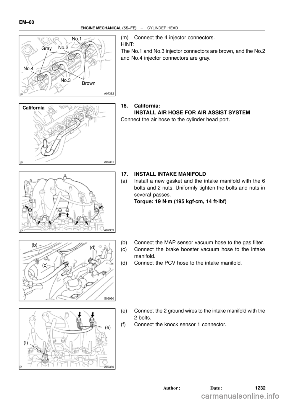
(m) Connect the 4 injector connectors.
HINT:
The No.1 and No.3 injector connectors are brown, and the No.2
and No.4 injector connectors are gray.
16. California:
INSTALL AIR HOSE FOR AIR ASSIST SYSTEM
Connect the air hose to the cylinder head port.
17. INSTALL INTAKE MANIFOLD
(a) Install a new gasket and the intake manifold with the 6
bolts and 2 nuts. Uniformly tighten the bolts and nuts in
several passes.
Torque: 19 N´m (195 kgf´cm, 14 ft´lbf)
(b) Connect the MAP sensor vacuum hose to the gas filter.
(c) Connect the brake booster vacuum hose to the intake
manifold.
(d) Connect the PCV hose to the intake manifold.
(e) Connect the 2 ground wires to the intake manifold with the
2 bolts.
(f) Connect the knock sensor 1 connector.
Page 3457 of 4770
A01565
Engine Wire Clamp
Brake Booster
Vacuum Hose
DLC1
Ground Strap
Connector
Generator
Wire
Wire
Clamp
Generator
ConnectorMAP Sensor
Vacuum HoseMAP Sensor
Connector
Fuel Inlet Hose
Engine
Wire
Starter
Connector
Starter
CableEngine
Wire
ProtectorGround
Cable (M/T)
Ground Strap Connector Wire
Clamp
Ground
Cable (A/T)
Heater
Hose
A01658
No.2 Instrument Panel
Under Cover
Cowl Side Trim Front Door Inside Scuff Plate
Engine Wire
± ENGINE MECHANICAL (5S±FE)ENGINE UNIT
EM±65
1237 Author�: Date�:
Page 3462 of 4770
ENGINE UNIT
1242 Author�: Date�:
(g) Disconnect the engine wire clamp from the bracket on the
RH fender apron.
(h) Disconnect the MAP sensor connector.
(i)")
S05253
EM±70
± ENGINE MECHANICAL (5S±FE)ENGINE UNIT
1242 Author�: Date�:
(g) Disconnect the engine wire clamp from the bracket on the
RH fender apron.
(h) Disconnect the MAP sensor connector.
(i) Disconnect the wire clamp from the bracket for the MAP
sensor.
(j) Disconnect the 2 ground strap connectors from the RH
fender apron.
(k) Disconnect the 2 ground strap connectors from the LH
fender apron.
(l) Disconnect the engine wire protector clamp from the bat-
tery bracket.
(m) Disconnect the engine wire from the clamp on the fuel fil-
ter.
(n) Disconnect the ground cable from the transaxle.
(o) Disconnect the brake booster vacuum hose from the in-
take manifold.
(p) Disconnect the heater hose from the water outlet.
(q) Disconnect the heater hose from the water bypass pipe.
(r) Disconnect the fuel inlet hose from the fuel filter.
(s) Disconnect the MAP sensor vacuum hose from the gas
filter on the intake manifold.
13. DISCONNECT ENGINE WIRE FROM CABIN
(a) Remove the under cover.
(b) Disconnect the 3 ECM connectors.
(c) Disconnect the 3 cowl wire connectors from the connec-
tors on the bracket.
(d) Disconnect the grommet from the cowl panel, and pull out
the engine wire.
14. REMOVE DRIVE SHAFTS (See page SA±17)
15. DISCONNECT TRANSAXLE CONTROL CABLE(S)
FROM TRANSAXLE
16. M/T:
REMOVE STARTER (See page ST±5)
17. M/T:
DISCONNECT CLUTCH RELEASE CYLINDER AND
TUBE FROM TRANSAXLE
Page 3472 of 4770
ENGINE UNIT
1252 Author�: Date�:
(b) Connect the generator connector.
(c) Install the wire clamp to the generator.
(d) Connect the starter cable.
(e) Connect")
S05251
EM±80
± ENGINE MECHANICAL (5S±FE)ENGINE UNIT
1252 Author�: Date�:
(b) Connect the generator connector.
(c) Install the wire clamp to the generator.
(d) Connect the starter cable.
(e) Connect the starter connector.
(f) Install the DLC1 to the bracket.
(g) Install the engine wire clamp to the bracket on the RH
fender apron.
(h) Connect the MAP sensor connector.
(i) Install the wire clamp to the bracket for the MAP sensor.
(j) Connect the VSV connector for the vapor pressure sen-
sor.
(k) Connect the 2 ground strap connectors to the RH fender
apron.
(l) Connect the 2 ground strap connectors to the LH fender
apron.
(m) Install the engine wire protector clamp to the battery
bracket.
(n) Install the engine wire to the clamp on the fuel filter.
(o) Connect the ground cable to the transaxle.
(p) Connect the brake booster vacuum hose to the intake
manifold.
(q) Connect the heater hose to the water outlet.
(r) Connect the heater hose to the water bypass pipe.
(s) Connect the fuel inlet hose to the fuel filter with 2 new gas-
kets and the union bolt.
Torque: 29 N´m (300 kgf´cm, 21 ft´lbf)
(t) Connect the MAP sensor vacuum hose to the gas filter on
the intake manifold.
33. INSTALL FRONT EXHAUST PIPE
(a) Install the support bracket with the nut.
Torque: 33 N´m (330 kgf´cm, 24 ft´lbf)
(b) Temporarily install 2 new gaskets and the front exhaust
pipe with the 2 bolts and 5 nuts.
(c) Tighten the 3 nuts holding the exhaust manifold to the
front exhaust pipe.
Torque: 62 N´m (630 kgf´cm, 46 ft´lbf)
(d) Tighten the 2 bolts and 2 nuts holding the front exhaust
pipe to the center exhaust pipe.
Torque: 56 N´m (570 kgf´cm, 41 ft´lbf)
(e) Install the bracket with the 2 bolts.
Torque: 33 N´m (330 kgf´cm, 24 ft´lbf)
(f) Install the support stay with the 2 bolts.
Torque: 33 N´m (330 kgf´cm, 24 ft´lbf)
34. INSTALL RADIATOR (See page CO±23)
35. INSTALL CRUISE CONTROL ACTUATOR
36. INSTALL BATTERY TRAY AND BATTERY
37. INSTALL AIR CLEANER CASE
Install the air cleaner case with the 3 bolts.
Page 3713 of 4770

IACIdle Air ControlIdle Speed Control (ISC)
IATIntake Air TemperatureIntake or Inlet Air Temperature")
IN±42
± INTRODUCTIONTERMS
42 Author�: Date�:
HO2SHeated Oxygen SensorHeated Oxygen Sensor (HO2S)
IACIdle Air ControlIdle Speed Control (ISC)
IATIntake Air TemperatureIntake or Inlet Air Temperature
ICMIgnition Control Module±
IFIIndirect Fuel InjectionIndirect Injection (IDL)
IFSInertia Fuel±Shutoff±
ISCIdle Speed Control±
KSKnock SensorKnock Sensor
MAFMass Air FlowAir Flow Meter
MAPManifold Absolute PressureManifold Pressure
Intake Vacuum
MCMixture Control
Electric Bleed Air Control Valve (EBCV)
Mixture Control Valve (MCV)
Electric Air Control Valve (EACV)
MDPManifold Differential Pressure±
MFIMultiport Fuel InjectionElectronic Fuel Injection (EFI)
MILMalfunction Indicator LampCheck Engine Lamp
MSTManifold Surface Temperature±
MVZManifold Vacuum Zone±
NVRAMNon±Volatile Random Access Memory±
O2SOxygen SensorOxygen Sensor, O2 Sensor (O2S)
OBDOn±Board DiagnosticOn±Board Diagnostic System (OBD)
OCOxidation Catalytic ConverterOxidation Catalyst Convert (OC), CCo
OPOpen LoopOpen Loop
PAIRPulsed Secondary Air InjectionAir Suction (AS)
PCMPowertrain Control Module±
PNPPark/Neutral Position±
PROMProgrammable Read Only Memory±
PSPPower Steering Pressure±
PTOXPeriodic Trap OxidizerDiesel Particulate Filter (DPF)
Diesel Particulate Trap (DPT)
RAMRandom Access MemoryRandom Access Memory (RAM)
RMRelay Module±
ROMRead Only MemoryRead Only Memory (ROM)
RPMEngine SpeedEngine Speed
SCSuperchargerSupercharger
SCBSupercharger BypassE±ABV
SFISequential Multiport Fuel InjectionElectronic Fuel Injection (EFI), Sequential Injection
SPLSmoke Puff Limiter±
SRIService Reminder Indicator±
SRTSystem Readiness Test±
STScan Tool±
TBThrottle BodyThrottle Body
TBIThrottle Body Fuel InjectionSingle Point Injection
Central Fuel Injection (Ci)
TCTurbochargerTurbocharger
TCCTorque Converter ClutchTorque Converter

Intake Manifold
Stay
Injector
(Except California)
Knock Sensor 1
Connec")