Page 23 of 4770

3
CAMRY ± NEW FEATURES
172CM14
Fuel
Pressure
SensorFuel Temp.
SensorFuel
Pressure
RegulatorFuel Shutoff ValveFuel Tank
Fuel Shutoff ValveRelief Valve
Inlet Check
Valve
Fuel Temp.
Sensor
Coupler
Tank Valve Assembly
Vent Tube Manual
Shutoff
Valve Oil
Separator
Fuel Shutoff Valve Injectors
Delivery Pipe Discharge
ValveFuel
Pressure
SensorFuel
Filter43
6. Fuel System
General
�The compressed gas [maximum pressure approximately 250 kg / cm
2 (3600 psi, 24.8 MPa) @ 21�C
(70�F)] from the CNG fuel tank located in the rear section of the vehicle is routed via a fuel filter to the
engine compartment. The pressure of the fuel is then reduced to 8 kg / cm
2 (114 psi, 785 kPa).
�A pressure regulator and injectors designed exclusively for CNG application have been adopted.
�A fuel pressure sensor and a fuel temperature sensor that are used for the correction of the fuel injection
volume are located on the delivery pipe.
�The fuel tank, pressure regulator, and the delivery pipe are provided with shutoff valves that shut off the
fuel when the ignition switch is turned OFF.
In addition, these valves shut off the fuel when the engine stalls, the SRS airbag is deployed, or the pres-
sure in the main pipe becomes abnormally low.
�A fuel temperature sensor for the fuel gauge is mounted on the tank valve assembly, and a fuel pressure
sensor is mounted immediately upstream of the pressure regulator.
� Fuel System Diagram �
Page 24 of 4770
CAMRY ± NEW FEATURES
167CN08
Tank Valve
AssemblyTank Band
Coil Springs
167CN26
Tank Valve AssemblyFuel
Temperature
Sensor 44
Fuel Tank
�A fuel tank made with carbon fiber and alumi-
num lining has been adopted to prevent weight
increase.
�Because the fuel tank expands along with the
increase in the pressure of the compressed gas,
the tank bands contain coil springs to accom-
modate the fluctuation in the perimeter of the
tank.
�The fuel tank is provided with a tank valve as-
sembly.
Tank Valve Assembly
1) General
The tank valve assembly is mounted on the
tank and consists of a fuel shutoff valve, inlet
check valve, relief valve and two manual cut-
off valves.
Page 25 of 4770

3
CAMRY ± NEW FEATURES
172CM17
CloseOpen45
2) Fuel Shutoff Valve for Fuel Tank
This valve uses an solenoid valve. The main pipe that supplies compressed gas to the engine is connected
to this valve, which opens when the ignition switch is turned ON. If the engine stalls, this valve automati-
cally shuts off the fuel even if the ignition switch is turned ON. The valve reopens upon restarting the
engine.
Also, this valve shuts off the fuel if the SRS airbag is deployed in a collision or if the pressure in the main
pipe becomes abnormally low.
3) Inlet Check Valve
Connected to a filler pipe that guides the fuel that fills through the coupler, the inlet check valve shuts
off by the force of a spring and by the pressure of the gas in the tank.
During filling, the pressure of the filling gas opens the inlet check valve.
4) Relief Valve
A vent tube is connected to this valve.
If the fuel tank is exposed to an abnormally high temperature, this valve opens (by melting) to discharge
the CNG at a predetermined temperature, thus helping prevent the fuel tank from bursting due to the in-
crease in gas pressure.
The discharged CNG is guided under the floor through a vent tube and is released outside of the vehicle.
Coupler
The coupler allows the fuel to be filled when it is connected with a fuel filling nozzle. The coupler has a
built-in check valve to help prevent the CNG from flowing backward.
Manual Shutoff Valve
This valve is mounted below the vehicle floor.
When servicing the vehicle, this valve can be
manually turned 90 degrees to shut off the main
pipe.
Page 33 of 4770

3
CAMRY ± NEW FEATURES
172CM18
172CM19
ON
OFF1 sec 1 sec
1 sec 1 sec
ON
OFF1 sec 1 sec
2 sec 2 sec 2 sec53
Injector Control
1) General
Fuel clearing control and injector unsticking control have been added to the injector control.
2) Fuel Clearing Control
While the vehicle is being driven at speeds higher than 60 km / h (37.5 mph), and the ignition switch is
turned OFF after the ECM has detected a low temperature condition of less than 25�C (77�F) of intake
air temperature, the ECM closes the fuel shutoff valve for the delivery pipe. However, instead of immedi-
ately stopping the engine, the fuel clearing control allows the engine to stop on its own after the fuel in
the delivery pipe has been used up. If the engine is running even after 2 seconds or more have elapsed
after the ignition switch has been turned OFF, the EFI relay is turned OFF to stop the engine.
3) Injector Unsticking Control
When the ignition switch is turned ON after executing the fuel clearing control, the injector unsticking
control activates two cylinders at a time to unstick the valve that is frozen stuck onto the valve seat. At
low temperature conditions. At this time, the shutoff valve remains closed so that the injectors will not
inject fuel.
Gas Leak Judgment
�If the ECM has detected a gas leak through the signals received from the pressure sensors, the ECM closes
the shutoff valves and flashes the low fuel level warning light.
�These functions are canceled by resetting the ECM (by disconnecting the negative [-] terminal of the bat-
tery), which enables the engine to start.
(The ECM should be reset only after performing a gas leak check and making sure that the leak has been
eliminated.)
NOTE: The low fuel level warning light also flashes when the fuel level is extremely low. The flashing
patterns shown below differentiates a gas leak from a low fuel level.
Flashing Pattern
Gas Leak
Fuel Low Level
Page 72 of 4770

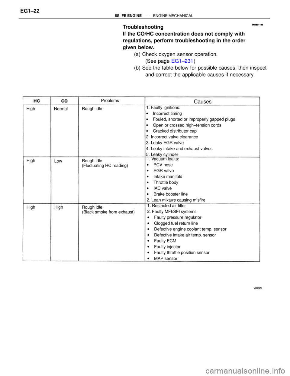
Troubleshooting
If the CO/HC concentration does not comply with
regulations, perform troubleshooting in the order
given below.
(a) Check oxygen sensor operation.
(See page EG1±231)
(b) See the table below for possible causes, then inspect
and correct the applicable causes if necessary.
1. Faulty ignitions:
wIncorrect timing
wFouled, shorted or improperly gapped plugs
wOpen or crossed high±tension cords
wCracked distributor cap
2. Incorrect valve clearance
3. Leaky EGR valve
4. Leaky intake and exhaust valves
5. Leaky cylinder
1. Restricted air filter
2. Faulty MFI/SFI systems
wFaulty pressure regulator
wClogged fuel return line
wDefective engine coolant temp. sensor
wDefective intake air temp. sensor
wFaulty ECM
wFaulty injector
wFaulty throttle position sensor
wMAP sensor 1. Vacuum leaks:
wPCV hose
wEGR valve
wIntake manifold
wThrottle body
w!AC valve
wBrake booster line
2. Lean mixture causing misfire
Rough idle
(Black smoke from exhaust) Rough idle
(Fluctuating HC reading) Rough idleProblems
Causes
Normal
High High High
HighLow
± 5S±FE ENGINEENGINE MECHANICALEG1±22
Page 73 of 4770

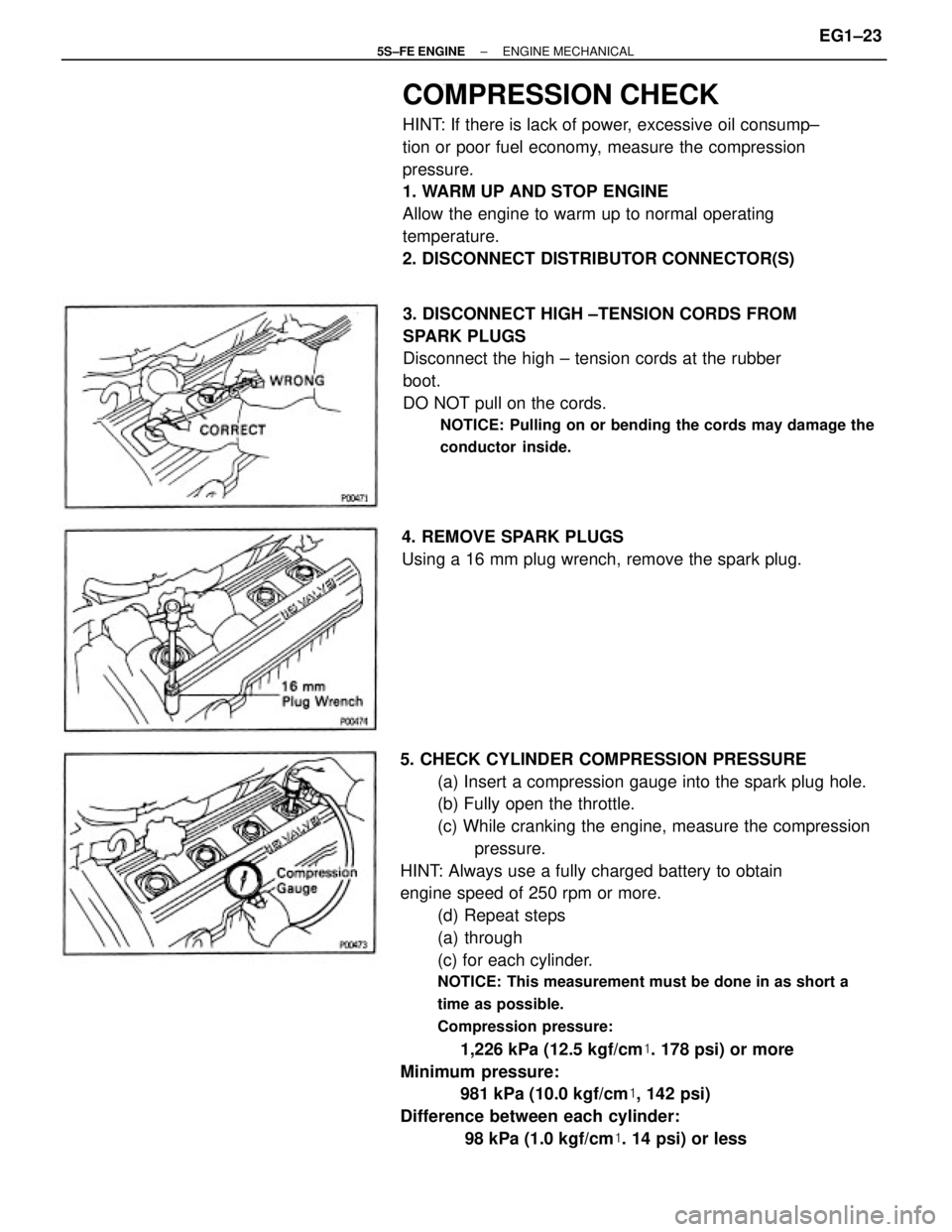
5. CHECK CYLINDER COMPRESSION PRESSURE
(a) Insert a compression gauge into the spark plug hole.
(b) Fully open the throttle.
(c) While cranking the engine, measure the compression
pressure.
HINT: Always use a fully charged battery to obtain
engine speed of 250 rpm or more.
(d) Repeat steps
(a) through
(c) for each cylinder.
NOTICE: This measurement must be done in as short a
time as possible.
Compression pressure:
1,226 kPa (12.5 kgf/cm�. 178 psi) or more
Minimum pressure:
981 kPa (10.0 kgf/cm�, 142 psi)
Difference between each cylinder:
98 kPa (1.0 kgf/cm�. 14 psi) or less
COMPRESSION CHECK
HINT: If there is lack of power, excessive oil consump±
tion or poor fuel economy, measure the compression
pressure.
1. WARM UP AND STOP ENGINE
Allow the engine to warm up to normal operating
temperature.
2. DISCONNECT DISTRIBUTOR CONNECTOR(S)
3. DISCONNECT HIGH ±TENSION CORDS FROM
SPARK PLUGS
Disconnect the high ± tension cords at the rubber
boot.
DO NOT pull on the cords.
NOTICE: Pulling on or bending the cords may damage the
conductor inside.
4. REMOVE SPARK PLUGS
Using a 16 mm plug wrench, remove the spark plug.
± 5S±FE ENGINEENGINE MECHANICALEG1±23
Page 199 of 4770
To reduce NC emissions, evaporated fuel from the fuel tank is routed through the charcoal canister to the intake manifold
for combustion in the cylinders.
EVAPORATIVE EMISSION (EVAP)
CONTROL SYSTEM
NC from tank is absorbed
into the canister
HC from tank is absorbed
into the canister. HC from canister is led
into air intake chamber.
Air is led into the fuel
tank. Positioned above
port P Positioned below
port P Engine Coolant
Temp.Throttle Valve
OpeningEvaporated Fuel (HC)
Above
54
�C (129�F)Canister Check Valve
High pressure
in tank
High vacuum
in tankBelow
35
�C (95�F)Check
Valve In
Cap
CLOSED
CLOSED
CLOSEDCLOSED CLOSED
OPEN
OPEN OPEN OPEN
OPEN TVV
± 5S±FE ENGINEEMISSION CONTROL SYSTEMSEG1±149
Page 200 of 4770

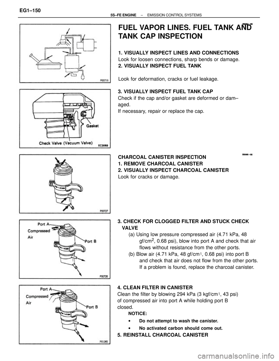
3. CHECK FOR CLOGGED FILTER AND STUCK CHECK
VALVE
(a) Using low pressure compressed air (4.71 kPa, 48
gf/cm
2, 0.68 psi), blow into port A and check that air
flows without resistance from the other ports.
(b) Blow air (4.71 kPa, 48 gf/cm�, 0.68 psi) into port B
and check that air does not flow from the other ports.
If a problem is found, replace the charcoal canister.
4. CLEAN FILTER IN CANISTER
Clean the filter by blowing 294 kPa (3 kgf/cm�, 43 psi)
of compressed air into port A while holding port B
closed.
NOTICE:
wDo not attempt to wash the canister.
wNo activated carbon should come out.
5. REINSTALL CHARCOAL CANISTER
FUEL VAPOR LINES. FUEL TANK AND
TANK CAP INSPECTION
1. VISUALLY INSPECT LINES AND CONNECTIONS
Look for loosen connections, sharp bends or damage.
2. VISUALLY INSPECT FUEL TANK
Look for deformation, cracks or fuel leakage.
CHARCOAL CANISTER INSPECTION
1. REMOVE CHARCOAL CANISTER
2. VISUALLY INSPECT CHARCOAL CANISTER
Look for cracks or damage. 3. VISUALLY INSPECT FUEL TANK CAP
Check if the cap and/or gasket are deformed or dam±
aged.
If necessary, repair or replace the cap.
± 5S±FE ENGINEEMISSION CONTROL SYSTEMSEG1±150