Page 204 of 4770
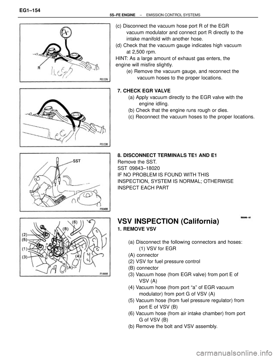
VSV INSPECTION (California)
1. REMOVE VSV
(a) Disconnect the following connectors and hoses:
(1) VSV for EGR
(A) connector
(2) VSV for fuel pressure control
(B) connector
(3) Vacuum hose (from EGR valve) from port E of
VSV (A)
(4) Vacuum hose (from port ªaº of EGR vacuum
modulator) from port G of VSV (A)
(5) Vacuum hose (from fuel pressure regulator) from
port E of VSV (B)
(6) Vacuum hose (from air intake chamber) from port
G of VSV (B)
(b) Remove the bolt and VSV assembly. (c) Disconnect the vacuum hose port R of the EGR
vacuum modulator and connect port R directly to the
intake manifold with another hose.
(d) Check that the vacuum gauge indicates high vacuum
at 2,500 rpm.
HINT: As a large amount of exhaust gas enters, the
engine will misfire slightly.
(e) Remove the vacuum gauge, and reconnect the
vacuum hoses to the proper locations.
8. DISCONNECT TERMINALS TE1 AND E1
Remove the SST.
SST 09843±18020
IF NO PROBLEM IS FOUND WITH THIS
INSPECTION, SYSTEM IS NORMAL; OTHERWISE
INSPECT EACH PART 7. CHECK EGR VALVE
(a) Apply vacuum directly to the EGR valve with the
engine idling.
(b) Check that the engine runs rough or dies.
(c) Reconnect the vacuum hoses to the proper locations.
± 5S±FE ENGINEEMISSION CONTROL SYSTEMSEG1±154
Page 220 of 4770
PREPARATION
SST (SPECIAL SERVICE TOOLS)
(90405±09015) No.1 Union (09268±41090) No.7 union (09268±41080) No.6 union
09631±22020 Power Steering Hose Nut
14 x 17 mm Wrench Set
RECOMMENDED TOOLS
Plug for vacuum hose, fuel hose
etc. 09268±41045 Injection Measuring Tool Set
09082±00050 TOYOTA Electrical Tester Set 09842±30070 Wiring ªFº EFI Inspection 09268±45012 EFI Fuel Pressure Gauge
09843±18020 Diagnosis Check Wire
09200±00010 Engine Adjust Kit
09258±00030 Hose Plug SetFuel line flare nut
± 5S±FE ENGINEMFI/SFI SYSTEMEG1±170
Page 226 of 4770
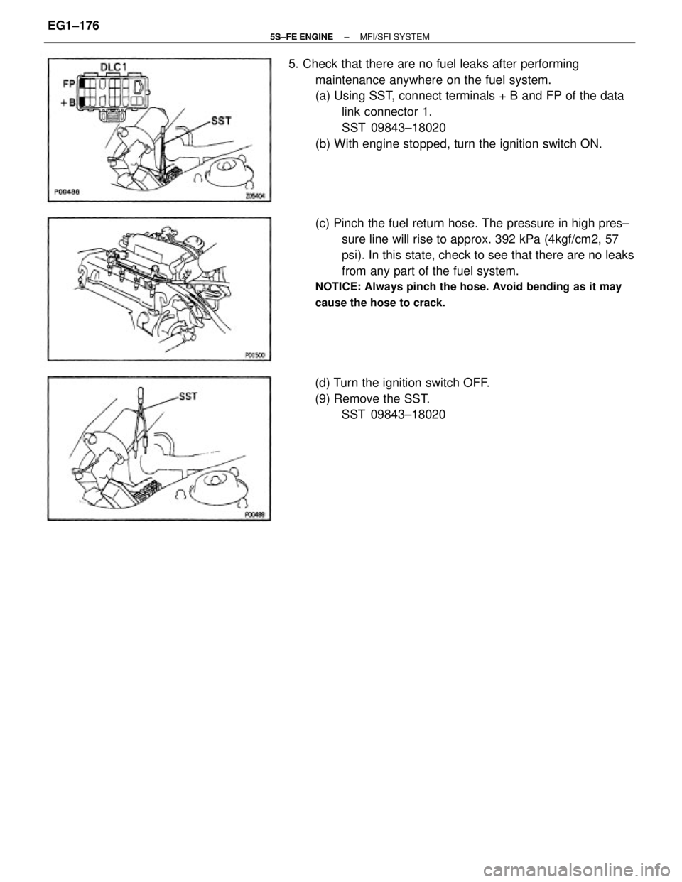
5. Check that there are no fuel leaks after performing
maintenance anywhere on the fuel system.
(a) Using SST, connect terminals + B and FP of the data
link connector 1.
SST 09843±18020
(b) With engine stopped, turn the ignition switch ON.
(c) Pinch the fuel return hose. The pressure in high pres±
sure line will rise to approx. 392 kPa (4kgf/cm2, 57
psi). In this state, check to see that there are no leaks
from any part of the fuel system.
NOTICE: Always pinch the hose. Avoid bending as it may
cause the hose to crack.
(d) Turn the ignition switch OFF.
(9) Remove the SST.
SST 09843±18020
± 5S±FE ENGINEMFI/SFI SYSTEMEG1±176
Page 228 of 4770
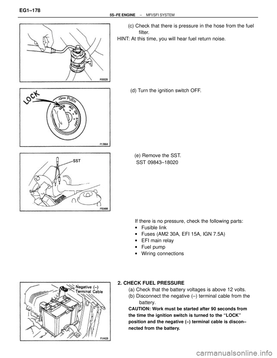
2. CHECK FUEL PRESSURE
(a) Check that the battery voltages is above 12 volts.
(b) Disconnect the negative (±) terminal cable from the
battery.
CAUTION: Work must be started after 90 seconds from
the time the ignition switch is turned to the ªLOCKº
position and the negative (±) terminal cable is discon±
nected from the battery.
If there is no pressure, check the following parts:
wFusible link
wFuses (AM2 30A, EFI 15A, IGN 7.5A)
wEFI main relay
wFuel pump
wWiring connections (c) Check that there is pressure in the hose from the fuel
filter.
HINT: At this time, you will hear fuel return noise.
(e) Remove the SST.
SST 09843±18020 (d) Turn the ignition switch OFF.
± 5S±FE ENGINEMFI/SFI SYSTEMEG1±178
Page 229 of 4770
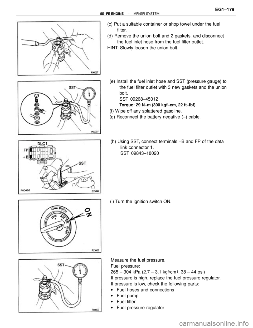
Measure the fuel pressure.
Fuel pressure:
265 ± 304 kPa (2.7 ± 3.1 kgf/cm�, 38 ± 44 psi)
If pressure is high, replace the fuel pressure regulator.
If pressure is low, check the following parts:
wFuel hoses and connections
wFuel pump
wFuel filter
wFuel pressure regulator (e) Install the fuel inlet hose and SST (pressure gauge) to
the fuel filter outlet with 3 new gaskets and the union
bolt.
SST 09268±45012
Torque: 29 N±m (300 kgf±cm, 22 ft±lbf)
(f) Wipe off any splattered gasoline.
(g) Reconnect the battery negative (±) cable. (c) Put a suitable container or shop towel under the fuel
filter.
(d) Remove the union bolt and 2 gaskets, and disconnect
the fuel inlet hose from the fuel filter outlet.
HINT: Slowly loosen the union bolt.
(h) Using SST, connect terminals +B and FP of the data
link connector 1.
SST 09843±18020
(i) Turn the ignition switch ON.
± 5S±FE ENGINEMFI/SFI SYSTEMEG1±179
Page 230 of 4770
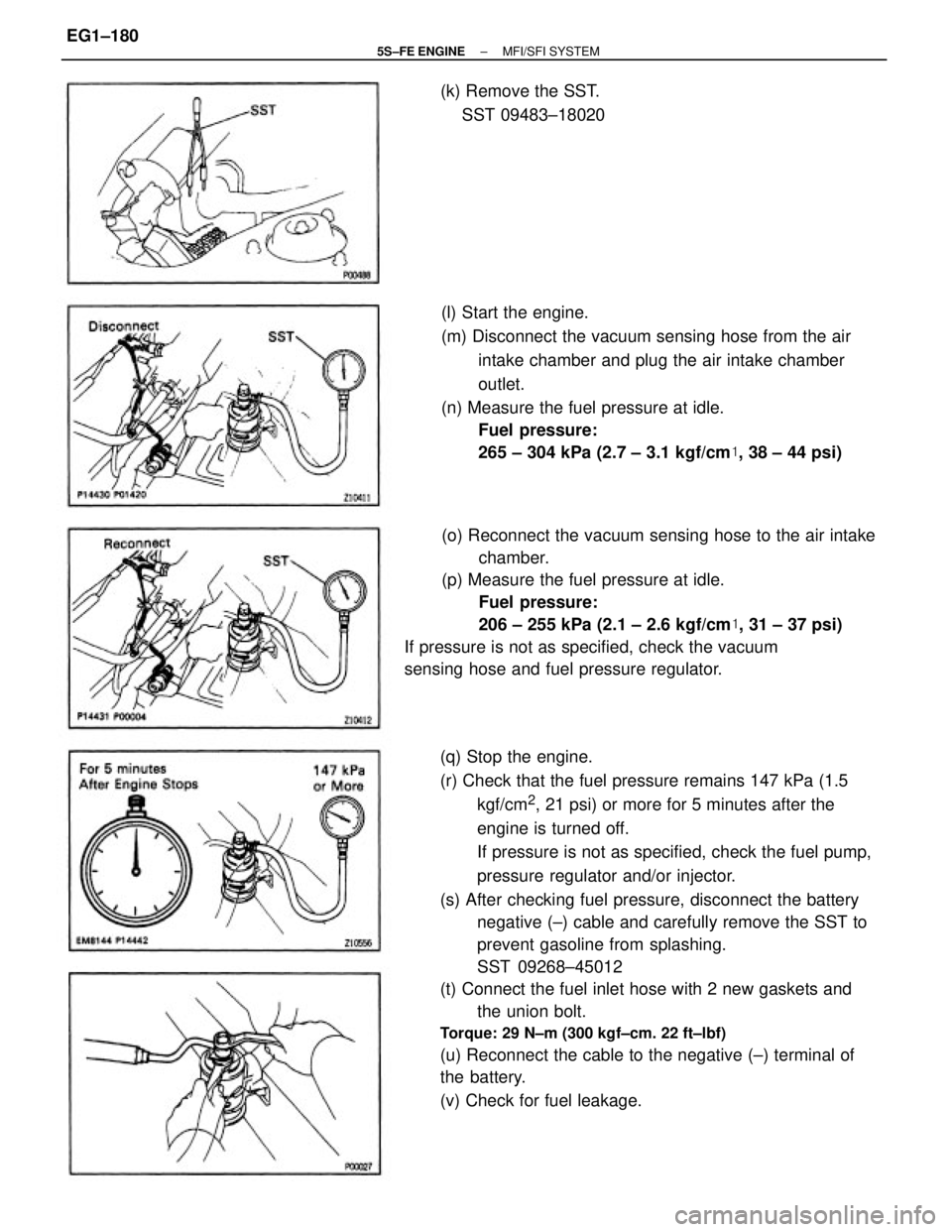
(q) Stop the engine.
(r) Check that the fuel pressure remains 147 kPa (1.5
kgf/cm
2, 21 psi) or more for 5 minutes after the
engine is turned off.
If pressure is not as specified, check the fuel pump,
pressure regulator and/or injector.
(s) After checking fuel pressure, disconnect the battery
negative (±) cable and carefully remove the SST to
prevent gasoline from splashing.
SST 09268±45012
(t) Connect the fuel inlet hose with 2 new gaskets and
the union bolt.
Torque: 29 N±m (300 kgf±cm. 22 ft±lbf)
(u) Reconnect the cable to the negative (±) terminal of
the battery.
(v) Check for fuel leakage.(o) Reconnect the vacuum sensing hose to the air intake
chamber.
(p) Measure the fuel pressure at idle.
Fuel pressure:
206 ± 255 kPa (2.1 ± 2.6 kgf/cm�, 31 ± 37 psi)
If pressure is not as specified, check the vacuum
sensing hose and fuel pressure regulator.(l) Start the engine.
(m) Disconnect the vacuum sensing hose from the air
intake chamber and plug the air intake chamber
outlet.
(n) Measure the fuel pressure at idle.
Fuel pressure:
265 ± 304 kPa (2.7 ± 3.1 kgf/cm�, 38 ± 44 psi) (k) Remove the SST.
SST 09483±18020
± 5S±FE ENGINEMFI/SFI SYSTEMEG1±180
Page 238 of 4770
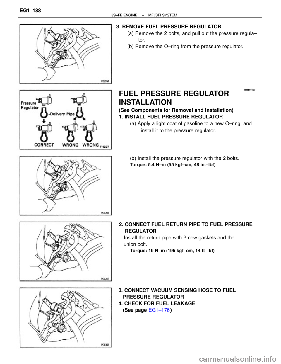
FUEL PRESSURE REGULATOR
INSTALLATION
(See Components for Removal and Installation)
1. INSTALL FUEL PRESSURE REGULATOR
(a) Apply a light coat of gasoline to a new O±ring, and
install it to the pressure regulator.
2. CONNECT FUEL RETURN PIPE TO FUEL PRESSURE
REGULATOR
Install the return pipe with 2 new gaskets and the
union bolt.
Torque: 19 N±m (195 kgf±cm, 14 ft±lbf)
3. REMOVE FUEL PRESSURE REGULATOR
(a) Remove the 2 bolts, and pull out the pressure regula±
tor.
(b) Remove the O±ring from the pressure regulator.
3. CONNECT VACUUM SENSING HOSE TO FUEL
PRESSURE REGULATOR
4. CHECK FOR FUEL LEAKAGE
(See page EG1±176) (b) Install the pressure regulator with the 2 bolts.
Torque: 5.4 N±m (55 kgf±cm, 48 in.±lbf)
± 5S±FE ENGINEMFI/SFI SYSTEMEG1±188
Page 273 of 4770
VSV INSPECTION (California)
1. REMOVE VSV
(a) Disconnect the following connectors and hoses:
(1) VSV for EGR (A) connector
(2) VSV for fuel pressure control (B) connector
(3) Vacuum hose (from EGR valve) from port E of
VSV (A)
(4) Vacuum hose (from port ªQº of EGR vacuum
modulator) from port G of VSV (A)
(5) Vacuum hose (from fuel pressure regulator) from
port E of VSV (B)
(6) Vacuum hose (from air intake chamber) from port
G of VSV (B)
(b) Remove the bolt and VSV assembly.
2. INSPECT VSV
A. Inspect VSV for open circuit
Using an ohmmeter, check that there is continuity
between the terminals.
Resistance (Cold):
33±39�
If there is no continuity, replace the VSV.
VSV FOR EGR
± 5S±FE ENGINEMFI/SFI SYSTEMEG1±223