Page 104 of 4770
(b) Lift the cylinder head from the dowels on the cylinder
block, and place the cylinder head on wooden blocks
on a bench.
HINT: If the cylinder head is difficult to lift off, pry
between the cylinder head and cylinder block with a
screwdriver.
NOTICE: Be careful not to damage the contact surfaces
of the cylinder head and cylinder block.
2. REMOVE VALVES
(a) Using SST, compress the valve spring and remove the
2 keepers.
SST 09202 ± 70010
(b) Remove the spring retainer, valve spring, valve and
spring seat.
CYLINDER HEAD DISASSEMBLY
(See Components for Removal and Installation)
1. REMOVE VALVE LIFTERS AND SHIMS
HINT: Arrange the valves, valve springs, spring seats
and spring retainers in correct order. HINT: Arrange the valve lifters and shims in correct
order.
± 5S±FE ENGINEENGINE MECHANICALEG1±54
Page 110 of 4770
(d) Check the valve overall length.
Standard overall length:
Intake
97.60 mm (3.8425 in.)
Exhaust
98.45 mm (3.8760 in.)
Minimum overall length:
Intake
97.1 mm (3.823 in.)
Exhaust
98.0 mm (3.858 in.)
If the overall length is less than minimum, replace the
valve.
(b) Check the valve seating position.
Apply a light coat of prussian blue (or white lead) to
the valve face. Lightly press the valve against the
seat. Do not rotate valve.
(c) Check the valve face and seat for the following:
If blue appears 360� around the face, the valve is
concentric. If not, replace the valve. (e) Check the surface of the valve stem tip for wear.
If the valve stem tip is worn, resurface the tip with a
grinder or replace the valve.
NOTICE: Do not grind off more than minimum.
8. INSPECT AND CLEAN VALVE SEATS
(a) Using a 45� carbide cutter, resurface the valve seats.
Remove only enough metal to clean the seats.
± 5S±FE ENGINEENGINE MECHANICALEG1±60
Page 580 of 4770

105 BODY ELECTRICALÐACCESSORIES
ACCESSORIES
� DESCRIPTION
The new Camry includes the accessory systems shown in the below.
System
Outline
Power Window System
The power window system includes one±touch auto down and key±off opera-
tion functions. The one±touch auto down function automatically opens the
driver 's door window fully. The key±off operation function makes it possible
to operate the power windows for approximately 45 seconds after the igni-
tion key is turned to the ACC or LOCK position, if the front doors are not
opened.
The basic construction and operation of this system are the same as in the
previous model.
Door Lock Control System
This system has a ªkey±linked lock and unlock functionº and a ªkey±confine
prevention functionº. All doors can be locked and unlocked simultaneously
by a key operation at the front right or left foor. (The key needs to be oper-
ated twice to unlock all the doors at the driver's door.) If the door lock opera-
tion is performed when one of the front doors is open and the ignition key is
inserted in the key cylinder, doors are unlocked automatically to prevent the
ignition key from being left inside the vehicle.
The basic construction and operation are the same as in the previous model.
Wireless Door Lock Remote Con-
trol System
A remote control system in which the lock and unlock functions of all doors
and panic alarm function can be controlled by the signals emitted from a
transmitter is adopted. The transmitter is also provided with a 2±step unlock
function to unlock all the doors by pressing the switch twice.
The basic construction and operation are the same as in the '96 Avalon.
However, certain functions have been changed. For details, see page 107.
Theft Deterrent System
When an attempt is made to forcibly enter the vehicle or open the hood or
trunk lid without a key, or when the battery terminals are removed and re-
connected, this system sounds the horn and flashes the headlights and tail-
lights for about 1 minute to alert the owner. At the same time, it locks all the
doors and electronically disconnects the starter.
The basic operation is the same as in the '96 Avalon.
Power Seat
As in the previous model, the front seats are power assisted by electric mo-
tors so that the seat positions can be adjusted easily by a simple switch op-
eration.
The basic construction and operation are the same as in the previous model.
Page 606 of 4770

GENERAL REPAIR INSTRUCTIONS
Work Precautions
SAFETY
Never stand in direct
line with the chain
when using a puller on
the body or frame, and
be sure to attach a
safety cable.SAFETY
1. Before performing repair work, check
for fuel leaks. If a leak is found, be
sure to close the opening totally.
2. If it is necessary to use a frame in the
area of the fuel tank, first remove the
tank and plug the fuel line. VEHICLE PROTECTION.
When welding, protect the
painted surfaces, windows,
seats and, carpet with heat±
resistant, fire±proof covers.
WRONG
Glass Cover
Safety Cable
Seat Cover
WRONG
SAFETY WORK CLOTHES
HAND TOOLS
Keeping your hand tools
in neat order improve
your work efficiency. In addition to the usual mechanic's wear, cap and safety shoes,
the appropriate gloves, head protector, glasses, ear plugs, face
protector, dust±prevention mask, etc. should be worn as the
situation demands.
Dust
Prevention
MaskWelder's
Glasses
Ear
Pugs
Body
Tools
Stand Face
Protector
Head
Protector Eye
Protector
Safety
ShoesWelder's
Gloves
INTRODUCTIONIN-9
Page 3433 of 4770
EM089±03
P03265
SST
P03266
± ENGINE MECHANICAL (5S±FE)CYLINDER HEAD
EM±41
1213 Author�: Date�:
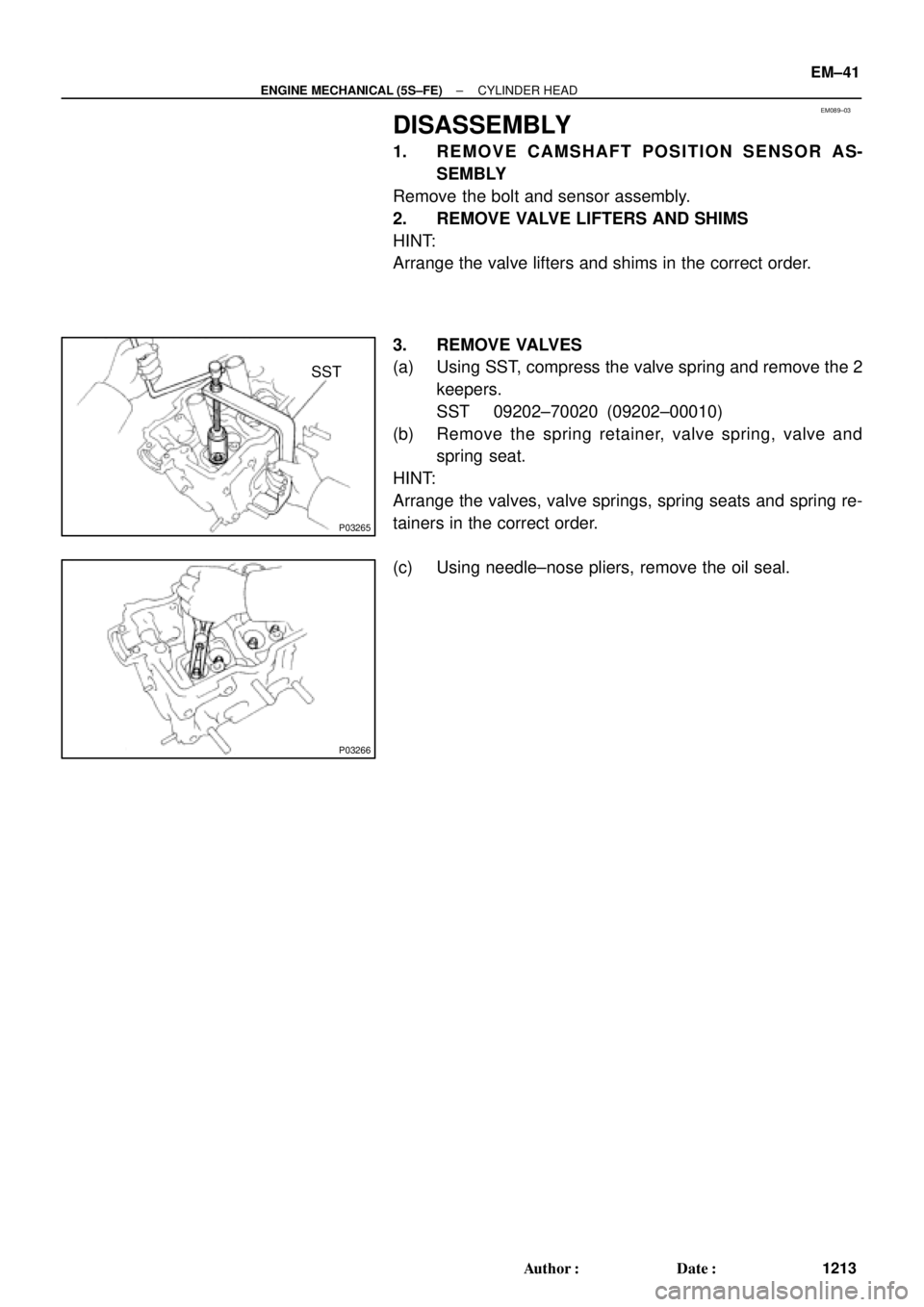
DISASSEMBLY
1. REMOVE CAMSHAFT POSITION SENSOR AS-
SEMBLY
Remove the bolt and sensor assembly.
2. REMOVE VALVE LIFTERS AND SHIMS
HINT:
Arrange the valve lifters and shims in the correct order.
3. REMOVE VALVES
(a) Using SST, compress the valve spring and remove the 2
keepers.
SST 09202±70020 (09202±00010)
(b) Remove the spring retainer, valve spring, valve and
spring seat.
HINT:
Arrange the valves, valve springs, spring seats and spring re-
tainers in the correct order.
(c) Using needle±nose pliers, remove the oil seal.
Page 3437 of 4770
CYLINDER HEAD
EM±45
1217 Author�: Date�:
(d) Check the valve overall length.
Standard overall length:")
EM2534
Overall Length
EM0255
P03272
45° Carbide
Cutter
Z00055
Width
± ENGINE MECHANICAL (5S±FE)CYLINDER HEAD
EM±45
1217 Author�: Date�:
(d) Check the valve overall length.
Standard overall length:
Intake97.40 ± 97.80 mm (3.8346 ± 3.8504 in.)
Exhaust98.25 ± 98.65 mm (3.8681 ± 3.8839 in.)
Minimum overall length:
Intake97.1 mm (3.823 in.)
Exhaust98.0 mm (3.858 in.)
If the overall length is less than minimum, replace the valve.
(e) Check the surface of the valve stem tip for wear.
If the valve stem tip is worn, resurface the tip with a grinder or
replace the valve.
NOTICE:
Do not grind off more than the minimum length.
8. INSPECT AND CLEAN VALVE SEATS
(a) Using a 45° carbide cutter, resurface the valve seats.
Remove only enough metal to clean the seats.
(b) Check the valve seating position.
Apply a light coat of prussian blue (or white lead) to the
valve face. Lightly press the valve against the seat. Do not
rotate valve.
(c) Check the valve face and seat for the following:
�If blue appears 360° around the face, the valve is
concentric. If not, replace the valve.
�If blue appears 360° around the valve seat, the
guide and face are concentric. If not, resurface the
seat.
�Check that the seat contact is in the middle of the
valve face with the following width:
1.0 ± 1.4 mm (0.039 ± 0.055 in.)
Page 3548 of 4770
EM04T±03
P12683
P12476
SST
P12686
P12720
Magnetic Finger EM±42
± ENGINE MECHANICAL (1MZ±FE)CYLINDER HEAD
1328 Author�: Date�:
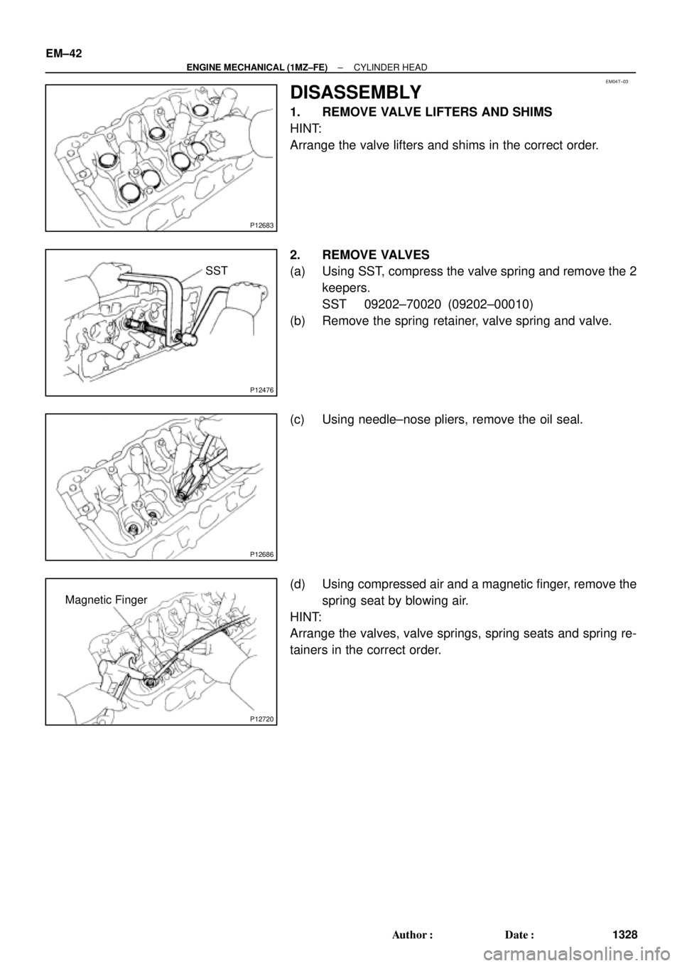
DISASSEMBLY
1. REMOVE VALVE LIFTERS AND SHIMS
HINT:
Arrange the valve lifters and shims in the correct order.
2. REMOVE VALVES
(a) Using SST, compress the valve spring and remove the 2
keepers.
SST 09202±70020 (09202±00010)
(b) Remove the spring retainer, valve spring and valve.
(c) Using needle±nose pliers, remove the oil seal.
(d) Using compressed air and a magnetic finger, remove the
spring seat by blowing air.
HINT:
Arrange the valves, valve springs, spring seats and spring re-
tainers in the correct order.
Page 3552 of 4770
CYLINDER HEAD
1332 Author�: Date�:
(d) Check the valve overall length.
Standard over")
EM2534
Overall Length
EM0255
P12704
P12729
Width
Z03988
45°
1.0 ± 1.4 mm30° EM±46
± ENGINE MECHANICAL (1MZ±FE)CYLINDER HEAD
1332 Author�: Date�:
(d) Check the valve overall length.
Standard overall length:
Intake95.45 mm (3.5779 in.)
Exhaust95.40 mm (3.7559 in.)
Minimum overall length:
Intake94.95 mm (3.7382 in.)
Exhaust94.90 mm (3.7362 in.)
If the overall length is less than minimum, replace the valve.
(e) Check the surface of the valve stem tip for wear.
If the valve stem tip is worn, resurface the tip with a grinder or
replace the valve.
NOTICE:
Do not grind off more than minimum.
11. INSPECT AND CLEAN VALVE SEATS
(a) Using a 45° carbide cutter, resurface the valve seats.
Remove only enough metal to clean the seats.
(b) Check the valve seating position.
Apply a light coat of prussian blue (or white lead) to the
valve face. Lightly press the valve against the seat. Do not
rotate valve.
(c) Check the valve face and seat for the following:
�If blue appears 360° around the face, the valve is
concentric. If not, replace the valve.
�If blue appears 360° around the valve seat, the
guide and face are concentric. If not, resurface the
seat.
�Check that the seat contact is in the middle of the
valve face with the following width:
1.0 ± 1.4 mm (0.039 ± 0.055 in.)
If not, correct the valve seats as follows:
(1) If the seating is too high on the valve face, use 30°
and 45° cutters to correct the seat.
 Lift the cylinder head from the dowels on the cylinder
block, and place the cylinder head on wooden blocks
on a bench.
HINT: If the cylinder head is difficult to lift off, pry
between the cylinder")
 Check the valve overall length.
Standard overall length:
Intake
97.60 mm (3.8425 in.)
Exhaust
98.45 mm (3.8760 in.)
Minimum overall length:
Intake
97.1 mm (3.823 in.)
Exhaust")