2000 TOYOTA CAMRY cruise control
[x] Cancel search: cruise controlPage 2 of 4770
9
8
7
6
5
4
3
2
1
GENERAL 2000 FEATURES
DESCRIPTION 2. . . . . . . . . . . . . . . . . . . . . . . . . . .
ENGINE
Evaporative Emission Control System3 . . . . . . . .
AUTOMATIC TRANSMISSION
Overdrive switch4 . . . . . . . . . . . . . . . . . . . . . . . . .
COROLLA
OUTLINE OF NEW FEATURES 6. . . . . . . . . . . .
MODEL CODE 7. . . . . . . . . . . . . . . . . . . . . . . . . .
MODEL LINE-UP 7. . . . . . . . . . . . . . . . . . . . . . . .
NEW FEATURES
1ZZ-FE Engine
Description8 . . . . . . . . . . . . . . . . . . . . . . . . . . . .
Major Difference9 . . . . . . . . . . . . . . . . . . . . . . .
Valve Mechanism10 . . . . . . . . . . . . . . . . . . . . . . .
Ignition System11 . . . . . . . . . . . . . . . . . . . . . . . .
Engine Control System12 . . . . . . . . . . . . . . . . . . .
Brakes
General20 . . . . . . . . . . . . . . . . . . . . . . . . . . . . . . .
System Diagram20 . . . . . . . . . . . . . . . . . . . . . . . .
Hydraulic Circuit20 . . . . . . . . . . . . . . . . . . . . . . .
Operation21 . . . . . . . . . . . . . . . . . . . . . . . . . . . . .
CAMRY
OUTLINE OF NEW FEATURES 26. . . . . . . . . . . .
MODEL CODE 29. . . . . . . . . . . . . . . . . . . . . . . . . . .
MODEL LINE-UP 30. . . . . . . . . . . . . . . . . . . . . . . . .
NEW FEATURES
Exterior31 . . . . . . . . . . . . . . . . . . . . . . . . . . . . . . . .
Interior32 . . . . . . . . . . . . . . . . . . . . . . . . . . . . . . . .
5S-FE Engine
Description33 . . . . . . . . . . . . . . . . . . . . . . . . . . . .
Major Difference34 . . . . . . . . . . . . . . . . . . . . . . .
Intake and Exhaust System34 . . . . . . . . . . . . . . .
Fuel System35 . . . . . . . . . . . . . . . . . . . . . . . . . . .
5S-FNE Engine
Description36 . . . . . . . . . . . . . . . . . . . . . . . . . . . .
Features of 5S-FNE Engine38 . . . . . . . . . . . . . . .
Engine Proper39 . . . . . . . . . . . . . . . . . . . . . . . . . .
Valve Mechanism40 . . . . . . . . . . . . . . . . . . . . . . .
Intake and Exhaust System41 . . . . . . . . . . . . . . .
Fuel System43 . . . . . . . . . . . . . . . . . . . . . . . . . . .
Ignition System48 . . . . . . . . . . . . . . . . . . . . . . . .
Engine Control System49 . . . . . . . . . . . . . . . . . . .
1MZ-FE Engine54 . . . . . . . . . . . . . . . . . . . . . . . . .
Automatic Transaxle54 . . . . . . . . . . . . . . . . . . . . . .
Brakes55 . . . . . . . . . . . . . . . . . . . . . . . . . . . . . . . . .
Steering56 . . . . . . . . . . . . . . . . . . . . . . . . . . . . . . . .
Body57 . . . . . . . . . . . . . . . . . . . . . . . . . . . . . . . . . . Lighting58 . . . . . . . . . . . . . . . . . . . . . . . . . . . . . . . .
Air Conditioning59 . . . . . . . . . . . . . . . . . . . . . . . . .
SRS Airbag59 . . . . . . . . . . . . . . . . . . . . . . . . . . . . .
CAMRY SOLARA
OUTLINE OF NEW FEATURES 62. . . . . . . . . . . .
MODEL CODE 64. . . . . . . . . . . . . . . . . . . . . . . . . . .
MODEL LINE-UP 64. . . . . . . . . . . . . . . . . . . . . . . . .
SIENNA
OUTLINE OF NEW FEATURES 66. . . . . . . . . . . .
MODEL CODE 67. . . . . . . . . . . . . . . . . . . . . . . . . . .
MODEL LINE-UP 67. . . . . . . . . . . . . . . . . . . . . . . . .
RAV4
OUTLINE OF NEW FEATURES 70. . . . . . . . . . . .
MODEL CODE 71. . . . . . . . . . . . . . . . . . . . . . . . . . .
MODEL LINE-UP 71. . . . . . . . . . . . . . . . . . . . . . . . .
TOYOTA TACOMA
OUTLINE OF NEW FEATURES 74. . . . . . . . . . . .
MODEL CODE 76. . . . . . . . . . . . . . . . . . . . . . . . . . .
MODEL LINE-UP 77. . . . . . . . . . . . . . . . . . . . . . . . .
NEW FEATURES
2RZ-FE and 3RZ-FE Engine
Description78 . . . . . . . . . . . . . . . . . . . . . . . . . . . .
LEV Compliance78 . . . . . . . . . . . . . . . . . . . . . . .
Differential82 . . . . . . . . . . . . . . . . . . . . . . . . . . . . .
4RUNNER
OUTLINE OF NEW FEATURES 84. . . . . . . . . . . .
MODEL CODE 86. . . . . . . . . . . . . . . . . . . . . . . . . . .
MODEL LINE-UP 86. . . . . . . . . . . . . . . . . . . . . . . . .
LAND CRUISER
OUTLINE OF NEW FEATURES 88. . . . . . . . . . . .
MODEL CODE 90. . . . . . . . . . . . . . . . . . . . . . . . . . .
MODEL LINE-UP 90. . . . . . . . . . . . . . . . . . . . . . . . .
NEW FEATURES
Engine91 . . . . . . . . . . . . . . . . . . . . . . . . . . . . . . . . .
Differential91 . . . . . . . . . . . . . . . . . . . . . . . . . . . . .
Brakes
General92 . . . . . . . . . . . . . . . . . . . . . . . . . . . . . . .
Function92 . . . . . . . . . . . . . . . . . . . . . . . . . . . . . .
System Diagram93 . . . . . . . . . . . . . . . . . . . . . . . .
Layout of Components94 . . . . . . . . . . . . . . . . . . .
2
TABLE OF CONTENTS
Page 3 of 4770
10
Function of Components95 . . . . . . . . . . . . . . . .
Construction and Operation of Main
Components96 . . . . . . . . . . . . . . . . . . . . . . . . . .
Operation98 . . . . . . . . . . . . . . . . . . . . . . . . . . . .
System Cooperative Control107 . . . . . . . . . . . . .
VSC Operation Prohibit Control107 . . . . . . . . . .
Self-Diagnosis107 . . . . . . . . . . . . . . . . . . . . . . . .
Fail-Safe108 . . . . . . . . . . . . . . . . . . . . . . . . . . . . .
Combination Meter108 . . . . . . . . . . . . . . . . . . . . . .
Wiper109 . . . . . . . . . . . . . . . . . . . . . . . . . . . . . . . .
APPENDIX
MAJOR TECNICAL SPECIFICATIONS
COROLLA11 2 . . . . . . . . . . . . . . . . . . . . . . . . . . . .
CAMRY11 6 . . . . . . . . . . . . . . . . . . . . . . . . . . . . . .
CAMRY SOLARA120 . . . . . . . . . . . . . . . . . . . . . .
SIENNA122 . . . . . . . . . . . . . . . . . . . . . . . . . . . . . .
RAV 4124 . . . . . . . . . . . . . . . . . . . . . . . . . . . . . . . .
TOYOTA TACOMA128 . . . . . . . . . . . . . . . . . . . .
4RUNNER132 . . . . . . . . . . . . . . . . . . . . . . . . . . . .
LAND CRUISER134 . . . . . . . . . . . . . . . . . . . . . . .
1
2
3
4
5
6
7
8
9
10
3
Page 135 of 4770

ENGINE REMOVAL
1. DISCONNECT NEGATIVE (±) TERMINAL CABLE
FROM BATTERY
CAUTION: Work must be started after 90 seconds from
the time the ignition switch is turned to the 'LOCK'
position and the negative (±) terminal cable Is discon±
nected from the battery.
2. REMOVE BATTERY AND TRAY
3. REMOVE HOOD
4. REMOVE ENGINE UNDER COVER
5. DRAIN ENGINE COOLANT
6. DRAIN ENGINE OIL
7. DISCONNECT ACCELERATOR CABLE FROM
THROTTLE BODY
8. A/T:
DISCONNECT THROTTLE CABLE FROM
THROTTLE BODY
9. REMOVE AIR CLEANER ASSEMBLY, RESONATOR
AND AIR CLEANER HOSE
(a) Disconnect the intake air temperature sensor connec±
tor.
(b) California only:
Disconnect the air hose from the air cleaner hose.
(c) Loosen the air cleaner hose clamp bolt.
(d) Disconnect the 4 air cleaner cap clips.
(e) Disconnect the air cleaner hose from the throttle
body, and remove the air cleaner cap together with
the resonator and air cleaner hose.
(f) Remove the element.
(g) Remove the 3 bolts and air cleaner case.
10. w/ CRUISE CONTROL SYSTEM:
REMOVE CRUISE CONTROL ACTUATOR
(a) Remove the actuator cover.
(b) Disconnect the actuator connector.
(c) Remove the 3 bolts, and disconnect the actuator with
the bracket.
11. REMOVE RADIATOR
± 5S±FE ENGINEENGINE MECHANICALEG1±85
Page 183 of 4770
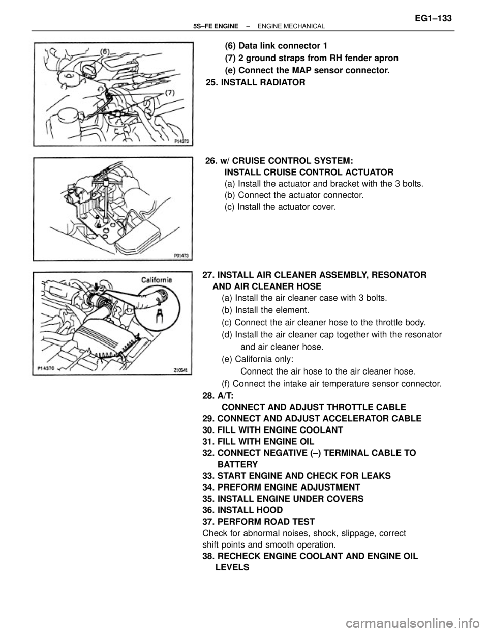
27. INSTALL AIR CLEANER ASSEMBLY, RESONATOR
AND AIR CLEANER HOSE
(a) Install the air cleaner case with 3 bolts.
(b) Install the element.
(c) Connect the air cleaner hose to the throttle body.
(d) Install the air cleaner cap together with the resonator
and air cleaner hose.
(e) California only:
Connect the air hose to the air cleaner hose.
(f) Connect the intake air temperature sensor connector.
28. A/T:
CONNECT AND ADJUST THROTTLE CABLE
29. CONNECT AND ADJUST ACCELERATOR CABLE
30. FILL WITH ENGINE COOLANT
31. FILL WITH ENGINE OIL
32. CONNECT NEGATIVE (±) TERMINAL CABLE TO
BATTERY
33. START ENGINE AND CHECK FOR LEAKS
34. PREFORM ENGINE ADJUSTMENT
35. INSTALL ENGINE UNDER COVERS
36. INSTALL HOOD
37. PERFORM ROAD TEST
Check for abnormal noises, shock, slippage, correct
shift points and smooth operation.
38. RECHECK ENGINE COOLANT AND ENGINE OIL
LEVELS26. w/ CRUISE CONTROL SYSTEM:
INSTALL CRUISE CONTROL ACTUATOR
(a) Install the actuator and bracket with the 3 bolts.
(b) Connect the actuator connector.
(c) Install the actuator cover.(6) Data link connector 1
(7) 2 ground straps from RH fender apron
(e) Connect the MAP sensor connector.
25. INSTALL RADIATOR
± 5S±FE ENGINEENGINE MECHANICALEG1±133
Page 302 of 4770

2. DRAIN ENGINE COOLANT (See page EG1±241)
3. w/ CRUISE CONTROL SYSTEM:
REMOVE CRUISE CONTROL ACTUATOR COVER
4. DISCONNECT ENGINE COOLANT TEMPERATURE
SWITCH CONNECTOR FROM FAN SHROUD
5. DISCONNECT ELECTRIC COOLING FAN
CONNECTORS
9. REMOVE RADIATOR AND ELECTRIC COOLING
FANS
(a) Remove the 2 bolts and 2 upper supports.
(b) Lift out the radiator.
(c) Remove the 2 lower radiator supports. 6. DISCONNECT RADIATOR HOSES
(a) Disconnect the upper hose from the radiator side.
(b) Disconnect the lower from the water inlet pipe.
7. DISCONNECT ENGINE COOLANT RESERVOIR
HOSE
10. REMOVE RADIATOR LOWER HOSE
11. A/T:
REMOVE A/T OIL COOLER HOSES 8. A/T:
DISCONNECT OIL COOLER HOSES
± 5S±FE ENGINECOOLING SYSTEMEG1±252
Page 310 of 4770

10. CONNECT ELECTRIC COOLING FAN CONNECTORS
11. CONNECT ENGINE COOLANT TEMPERATURE
SWITCH CONNECTOR TO FAN SHROUD
12. w/ CRUISE CONTROL SYSTEM:
INSTALL CRUISE CONTROL ACTUATOR COVER
13. FILL WITH ENGINE COOLANT
(See page EG1±241)
14. CONNECT NEGATIVE (±) TERMINAL CABLE TO
BATTERY
15. START ENGINE AND CHECK FOR LEAKS
16. A/T:
CHECK AUTOMATIC TRANSMISSION (A/T) FLUID
LEVEL
NOTICE: Do not overfill.
± 5S±FE ENGINECOOLING SYSTEMEG1±260
Page 315 of 4770
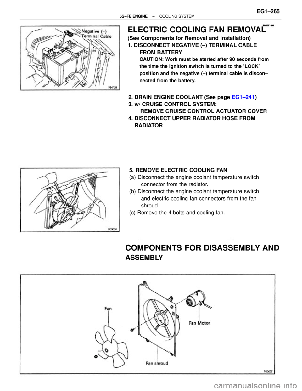
ELECTRIC COOLING FAN REMOVAL
(See Components for Removal and Installation)
1. DISCONNECT NEGATIVE (±) TERMINAL CABLE
FROM BATTERY
CAUTION: Work must be started after 90 seconds from
the time the ignition switch is turned to the 'LOCK'
position and the negative (±) terminal cable is discon±
nected from the battery.
5. REMOVE ELECTRIC COOLING FAN
(a) Disconnect the engine coolant temperature switch
connector from the radiator.
(b) Disconnect the engine coolant temperature switch
and electric cooling fan connectors from the fan
shroud.
(c) Remove the 4 bolts and cooling fan. 2. DRAIN ENGINE COOLANT (See page EG1±241)
3. w/ CRUISE CONTROL SYSTEM:
REMOVE CRUISE CONTROL ACTUATOR COVER
4. DISCONNECT UPPER RADIATOR HOSE FROM
RADIATOR
COMPONENTS FOR DISASSEMBLY AND
ASSEMBLY
± 5S±FE ENGINECOOLING SYSTEMEG1±265
Page 316 of 4770
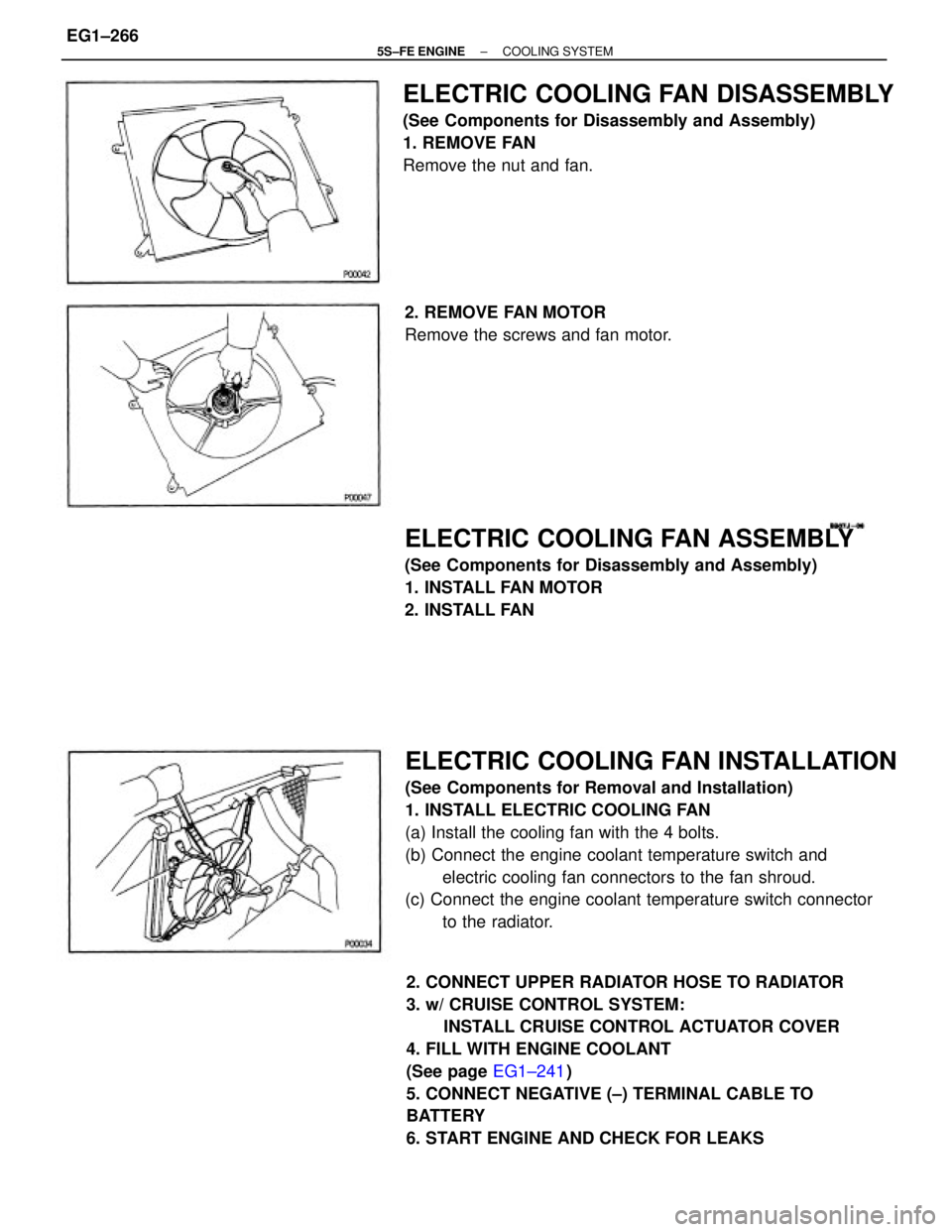
ELECTRIC COOLING FAN INSTALLATION
(See Components for Removal and Installation)
1. INSTALL ELECTRIC COOLING FAN
(a) Install the cooling fan with the 4 bolts.
(b) Connect the engine coolant temperature switch and
electric cooling fan connectors to the fan shroud.
(c) Connect the engine coolant temperature switch connector
to the radiator.
2. CONNECT UPPER RADIATOR HOSE TO RADIATOR
3. w/ CRUISE CONTROL SYSTEM:
INSTALL CRUISE CONTROL ACTUATOR COVER
4. FILL WITH ENGINE COOLANT
(See page EG1±241)
5. CONNECT NEGATIVE (±) TERMINAL CABLE TO
BATTERY
6. START ENGINE AND CHECK FOR LEAKS
ELECTRIC COOLING FAN DISASSEMBLY
(See Components for Disassembly and Assembly)
1. REMOVE FAN
Remove the nut and fan.
ELECTRIC COOLING FAN ASSEMBLY
(See Components for Disassembly and Assembly)
1. INSTALL FAN MOTOR
2. INSTALL FAN 2. REMOVE FAN MOTOR
Remove the screws and fan motor.
± 5S±FE ENGINECOOLING SYSTEMEG1±266