Page 56 of 4770
Plug for vacuum hose, fuel hose
etc.
Battery specific gravity gauge09256±00030 Hose Plug Set
09904±00010 Expander Set
Piston ring compressorEngine tune±up tester Connecting rod aligner
Precision straight edge
EQUIPMENT
Piston ring expander Compression gauge
Magnetic finger Cylinder gauge
Torque wrenchDye penetrant CO/HC meterCaliper gauge
Spring tester
ThermometerDial indicator
Steel squareMicrometer
Valve spring
Valve spring Plastigage
Soft brushHeater
± 5S±FE ENGINEENGINE MECHANICALEG1±6
Page 94 of 4770
11. DISCONNECT OIL PRESSURE SWITCH
CONNECTOR
12. DISCONNECT ENGINE WIRE (FOR OXYGEN
SENSORS) FROM ENGINE HANGER
13. REMOVE WATER OUTLET
(a) Disconnect the following connectors:
(1) Engine coolant temperature sender gauge con±
nector
(2) Engine coolant temperature sensor connector
(b) Disconnect the following hoses:
(1) Upper radiator hose
(2) Water bypass pipe hose
(3) Heater water hose
(4) IAC water bypass hose
(5) 2 TVV (for EVAP) vacuum hoses
14. REMOVE WATER BYPASS PIPE
(a) Disconnect the following hoses:
(1) IAC water bypass hose
(2) Heater water hose
(3) w/ Oil Cooler:
2 oil cooler water bypass hoses (5) 3 bolts and 2 nuts
(6) Exhaust manifold
(7) Gasket
(8) Retainer
(9) Cushion
(10) WU±TWC
(c) Remove the 2 bolts, water outlet and gasket.
± 5S±FE ENGINEENGINE MECHANICALEG1±44
Page 129 of 4770
(b) Connect the following hoses:
(1) Upper radiator hose
(2) Water bypass pipe hose
(3) Heater water hose
(4) IAC water bypass hose
(5) TVV (for EVAP) vacuum hose (from P port of
throttle body)
(6) TVV (for EVAP) vacuum hose (from charcoal canister) 27. INSTALL WATER BYPASS PIPE
(a) Install a new 0±ring to the bypass pipe.
(b) Apply soapy water on the 0± ring.
(c) Install a new gasket and the bypass pipe with the 2
nuts and 2 bolts.
Torque (Nut): 8.8 N±m (90 kgf±cm. 78 in.±lbf)
28. INSTALL WATER OUTLET
(a) Install a new gasket and the water outlet with the 2
bolts.
Torque: 15 N±m (150 kgf±cm, 11 ft±lbf)
(d) Connect the following hoses:
(1) IAC water bypass hose
(2) Heater water hose
(3) w/ Oil Cooler:
2 oil cooler water bypass hoses (f) Connect the IAC valve connector.
(g) Connect the throttle position sensor connector.
± 5S±FE ENGINEENGINE MECHANICALEG1±79
Page 136 of 4770
(c) Disconnect the following connectors:
(1) Igniter connector
(2) California only:
Ignition coil connector
(3) Noise filter connector
(4) 2 ground straps from LH fender apron
(5) Connector from LH fender apron 12. DISCONNECT WIRES AND CONNECTORS
(a) Remove the engine relay box, and disconnect the 5
connectors.
(b) Connector from LH fender apron
(6) Data link connector 1
(7) 2 ground straps from RH fender apron
(d) Disconnect the MAP sensor connector.
13. DISCONNECT HEATER HOSES
14. DISCONNECT FUEL RETURN HOSE
CAUTION: Catch leaking fuel in a container.
± 5S±FE ENGINEENGINE MECHANICALEG1±86
Page 182 of 4770
(d) Connect the following connectors:
(1) Igniter connector
(2) California only:
Ignition coil connector
(3) Noise filter connector
(4) 2 ground straps from LH fender apron
(5) Connector from LH fender apron 24. CONNECT WIRES AND CONNECTORS
(a) Connect the 5 connectors to the relay box.
(b) Connectors from LH fender apron.
(c) Install the engine relay box. 21. CONNECT FUEL INLET HOSE
Torque: 29 N±m (300 kgf±cm, 22 ft±lbf)
22. CONNECT FUEL RETURN HOSE
23. CONNECT HEATER HOSES
± 5S±FE ENGINEENGINE MECHANICALEG1±132
Page 301 of 4770
2. INSPECT COOLING SYSTEM FOR LEAKS
(a) Fill the radiator with coolant and attach a radiator cap
tester.
(b) Warm up the engine.
(c) Pump it to 118 kPa (1.2 kgf/cm�, 17.1 psi), and check
that the pressure does not drop.
If the pressure drops, check the hoses, radiator or
water pump for leaks. If no external leaks are found,
check the heater core, cylinder block and head.
RADIATOR REMOVAL
1. DISCONNECT NEGATIVE (±) TERMINAL CABLE
FROM BATTERY
CAUTION: Work must be started after 90 seconds from
the time the ignition switch is turned to the ªLOCKº
position and the negative (±) terminal cable is discon±
nected from the battery.
COMPONENTS FOR REMOVAL AND
INSTALLATION
± 5S±FE ENGINECOOLING SYSTEMEG1±251
Page 1548 of 4770
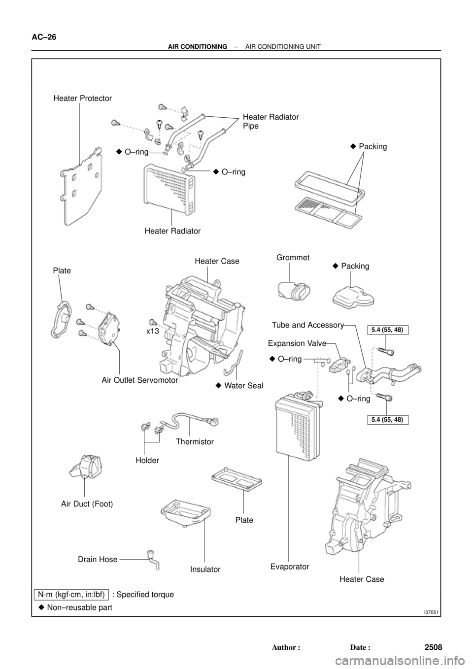
I07051
Heater Protector
Heater Radiator
Pipe
� Packing
� O±ring
� O±ring
Heater Radiator
Plate
Heater CaseGrommet
� Packing
x13
Air Outlet Servomotor� Water Seal
Air Duct (Foot)
Holder
Thermistor
5.4 (55, 48)
5.4 (55, 48)
� O±ring
� O±ring
Tube and Accessory
Expansion Valve
Drain Hose
Insulator
Plate
Evaporator
Heater Case
N´m (kgf´cm, in:lbf) : Specified torque
� Non±reusable part
AC±26
± AIR CONDITIONINGAIR CONDITIONING UNIT
2508 Author�: Date�:
Page 1549 of 4770

AC21W±01
N20288
N20237
Water Hose
MarkingUpper
LH
Hose ClipRH Heater Radiator Pipe
45 ± 10°
Lower
I09160
± AIR CONDITIONINGAIR CONDITIONING UNIT
AC±27
2509 Author�: Date�:
REMOVAL
1. DISCHARGE REFRIGERANT FROM REFRIGERATION
SYSTEM
HINT:
At the time of installation, please refer to the following item.
Evacuate air from refrigeration system.
Charge system with refrigerant and inspect for leakage of refrig-
erant.
Specified amount: 800 ± 50 g (28.22 ± 1.76 oz.)
2. DRAIN ENGINE COOLANT FROM RADIATOR
HINT:
It is not necessary to drain out all the coolant.
3. DISCONNECT WATER HOSE FROM HEATER RADIA-
TOR PIPES
(a) Using pliers, grip the claws of the hose clip and slide the
hose clip along the hose.
(b) Disconnect the water hose.
HINT:
At the time of installation, please refer to the following items.
�Push the water hose onto the heater radiator pipe as far
as ridge on the pipe and install the hose clip.
�Install the hose clip in a position, as shown in the illustra-
tion.
4. REMOVE BLOWER UNIT (See page AC±35)
5. REMOVE INSTRUMENT PANEL AND REINFORCE-
MENT (See page BO±75)
6. DISCONNECT LIQUID AND SUCTION TUBES
(a) Using SST, remove the 2 piping clamps.
SST 09870±00015 (Suction tube)
09870±00025 (Liquid tube)

 FROM ENGINE HANGER
13. REMOVE WATER OUTLET
(a) Disconnect the following connectors:
(1) Engine coolant")
 Connect the following hoses:
(1) Upper radiator hose
(2) Water bypass pipe hose
(3) Heater water hose
(4) IAC water bypass hose
(5) TVV (for EVAP) vacuum hose (from P port of
t")
 Disconnect the following connectors:
(1) Igniter connector
(2) California only:
Ignition coil connector
(3) Noise filter connector
(4) 2 ground straps from LH fender apron
(5) Connector from LH fe")
 Connect the following connectors:
(1) Igniter connector
(2) California only:
Ignition coil connector
(3) Noise filter connector
(4) 2 ground straps from LH fender apron
(5) Connector from LH fende")