Page 456 of 4770
Remove EFI main relay from J/B No±2.
Check continuity between terminals of EFI main
relay shown below.
Remove IGN fuse from J/B No.1.
Check continuity of IGN fuse.(1) Apply battery voltage between terminals 1
and 2.
(2) Check continuity between terminals 3 and 5.
Check for short in all the harness and
components connected to IGN fuse (See
attached wiring diagram).
Check EFI main relay.
Continuity
(Reference value 72�)
Replace EFI main relay.
Check IGN fuse.
Terminals 3 and 5
Terminals 1 and 2
Terminals 3 and 5 ContinuityOpen
Continuity
± 5S±FE ENGINECIRCUIT INSPECTIONEG1±406
Page 457 of 4770
Check for open in harness and connector between IG switch and
EFI main relay, EFI main relay and body ground (See page IN±31).
Remove EFI fuse from J/B No.2.
Check continuity of EFI fuse.
Continuity
Check for open in harness and connector
between EFI main relay and battery, EFI main
relay and engine control module.Check for short in all the harness and
components connected to EFI fuse (See
attached wiring diagram). Remove under cover and finish panel.
Check continuity between terminals.
Repair or replace harness or connector.
Check ignition switch.
Replace ignition switch.
Check EFI fuse.
Switch positioncontinuity
10
AM2 Terminal
4
AM1 3
ACC6
ST27
ST19
IG2
START2
lG1
LOCK
ACC
± 5S±FE ENGINECIRCUIT INSPECTIONEG1±407
Page 458 of 4770
CIRCUIT DESCRIPTION
Battery positive voltage is supplied to terminal BATT of the ECM even when the ignition switch is off
for use by the diagnostic trouble code memory and air±fuel ratio adaptive control value memory, etc.
Back Up Power Source Circuit
Proceed to next circuit inspection
shown on matrix chart (See page EG1±327).Check and repair harness or connector
between battery, EFI fuse and ECU. Check for short in all the harness and
components connected to EFI fuse.
DIAGNOSTIC CHART
Check operation for the back up. Check voltage of terminal6ATT.
WIRING DIAGRAM
Check and replace ECM. Check EFI fuse.
± 5S±FE ENGINECIRCUIT INSPECTIONEG1±408
Page 459 of 4770
Remove glove compartment.
(See page EG1±234)
Measure voltage between terminal BATT of en±
gine control module connector and body ground.
Voltage: 9 ±14 V
Check voltage between terminal BATT of engine control module
connector and body ground.
Are the diagnostic trouble codes still in the memory when the
ignition switch is turned OFF?
Check and repair harness or connector
between engine control module and EN
fuse, EFI fuse and battery. Remove EFI fuse from J/B No.2.
Check continuity of EFI fuse.
Continuity
Check for short in all the harness and
components connected to EFI fuse
(See attached wiring diagram).
Proceed to next circuit inspection shown on
matrix chart (See page EG1±327).Check and replace engine control module.
INSPECTION PROCEDURE
Check EFI fuse.
Others
YES
± 5S±FE ENGINECIRCUIT INSPECTIONEG1±409
Page 1158 of 4770

transmits current to. In the Power Source circuit diagram, the conditions whe")
B
The ºCurrent Flow Chartº section, describes which parts each power source (fuses, fusible links, and circuit breakers)
transmits current to. In the Power Source circuit diagram, the conditions when battery power is supplied to each system
are explained. Since all System Circuit diagrams start from the power source, the power source system must be fully
understood.
Theft Deterrent and Door Lock Control
K POWER SOURCE (Current Flow Chart)
11
1
EA1 1EA2 3
7
EB16
E 6
E 7I 2I 2
I 2
E 7
E 7
E 7
2
1
1
2
2
2
2
2
B
B
W W
B B B B BW±B
B
B
B B±O
B±W
W±B
B±W STARTER RELAY INJECTION RELAY15A HAZ±RADIO7.5A AM250A MAIN 1.25B FL MAIN
BATTERY
WWW
W W W
R W±L
W
W
G±W
G
15A TAIL
20A DEFOG
15A RAD CIGTA I L
RELAY 7.5A DOME 40A DOOR LOCK CB
2 1
1 2
4 8
2 3
3 4
G
W±R
P±L B±Y
B±Y
W±R
AM2 IG2
ACC
IG1AM1W W
W±R
W W
W±B
21
1
1
1
1
2
2
2
2
3
4
3
4 1
2
1
22
1
11
1
IGNITION SW I 8
Battery
30A AM2
2
Starter S 220A RADIO NO.1
10A HORN
15A EFI
7.5A DOMEShort Pin
10A HAZARD
The chart below shows the route by which current flows from the battery to each electrical source
(Fusible Link, Circuit Breaker, Fuse, etc.) and other parts.
Engine Room R/B (See Page 20)
ABS
ABS and Traction Control
Cruise Control
Electronically Controlled Transmission and A/T Indicator
Multiplex Communication System
Cigarette Lighter and Clock
Key Reminder and Seat Belt Warning STOP
Fuse Page
194
214
11 2
System
DOME 20A
10ACombination Meter
Headlight
Interior Light
2
2
6 100A ALT
EB1
POWER SOURCE
Light Auto Turn Off187
180
166
210
230
122
10A ECU±B
5 60A ABS
2
6 Fusible Link Block2
* The system shown here is an EXAMPLE ONLY. It is different to the actual circuit shown in the SYSTEM CIRCUITS SECTION.
Page 1467 of 4770

10 D
P22 D
L±Y19 D
R± B
23 D
L
2DY
17 A
P
22 E
W± G
13 D
G±Y
14 D
G±B
18 D
BR
19 A
G±O
18 A
B±Y
15 A
G±W
2 EC1 4 EC1 1 EC1 3")
J OVERALL ELECTRICAL WIRING DIAGRAM
9
1011 12
2 CAMRY (
Cont ' d)
10 D
P22 D
L±Y19 D
R± B
23 D
L
2DY
17 A
P
22 E
W± G
13 D
G±Y
14 D
G±B
18 D
BR
19 A
G±O
18 A
B±Y
15 A
G±W
2 EC1 4 EC1 1 EC1 3 EC1
111 2 1
2 1
1 2
28 E 27 E 16 D 24 D 10 E 9 D
WW WWB±RBRL B±W
L B±L
BR BR BR
YY
BR BR
513 3321312
Y Y
BRBR BR
BR
GR(
*4)
B±O(
*5)
ENGINE CONTROL MODULE
BRFr om Stop Li ght SW
< 11±4>
Fr om º MI RROR±HEATERº
Fuse< 26±2>
Fr om º TAI Lº Fus e
< 11±2>
E 5
ENGINE COOLANT
TEMP. SENSOR
E 1
EGR GAS TEMP.
SENSOR E 2
EGR VALVE POSITI ON
SENSOR
V 1
VAPOR PRESSURE
SENSOR
T 2
THROTTLE POSITION
SENSORM 2
MASS AIR FLOW
METER
(
Shielded)(
Shielded) (
Shielded)
(
Shielded)(
Shielded) (
Shielded)
From Park/Neutral
St ar t SW(
A/T)
or
Cl u t ch St ar t S W(
M/T)
< 1±2> C 1
CA MS HA FT P OS I T I ON
SENSOR
C 2
CRANKSHAFT POSITION
SENSOR
B±WPS STA G22+NE± NE + KNKR KNKLPT NK VCC
VG THA E2G VTA1 VC PTNK EGLS THG THW E2 ELS ELS2 STPE2
E2
VC VT A
P 2
POWE R S T EE RI NG
OI L PRESSURE SW
K 1
KNOCK SENSOR 1
K 2
KNOCK SENSOR 2
2 1
1 229 E 27 B
1II2
G±W G±W
FA FA
DBB±O B±OB±O
Fr om FAN NO. 1 Rel ay
< 26±3>To A/C Amplifier
< 27±3>
To A/ C Con tro l
Assembly< 29±8> To Tac home te r
[Comb. Meter]
< 25±5>
CF TACH
JUNCTION CONNECTOR
Engine Control and Engine Immobiliser System(
1M Z±FE)
EC Surge
t ank RH
BRE 24
BRD 17
BRE 30
BRE 31
BRE 21
A
A
A
AA
A
A
A
BR A
A
J22
JUNCTION
CONNECTORE01 E02 E03 E1 ADJ2
B
C
D
E
F
G10 C
TXCT 5C
RXCK 4C
CODE 16 C
IMLD 11 C
KSW
IE Co wl si d e
panel LH
BRE05
BRE04 4IG3 8IG315
234
G±WR±LL±Y
B±Y
BR
BR
BR
BR
BRBR
BRBRT 7
TRANSPONDER
KEY AMPLI FIER
R±Y
L±B R± Y
W± B
BR
BR
BR
B±Y BR
24
B
B
BJ26
JUNCTI ON
CONNE CTOR
B 6ID1
P
A
BR
B J27 J28A,
, E 8 E 7A B, E 9C, E10D, E11E
To Theft
Det er rent ECU
< 15±3>
To Unlock
Warning SW
< 21±3>(
*1)
(
*1)
(
*1) (
*1)
(
*1) (
*1)
* 1 : California
AB±Y
W± B
* 2 : Except California
(
*3) (
*3) (
*3)
(
*3)(
*3)
(
*3)
8D 1D
(
*5 M/T)
* 3 : w/ Engine Immobiliser System
7A
L±B
(
*2) 20 B
B±W
From º STARTERº Fuse
<1±2>NSW3II1
Y Y
2ID1 II14
BRY
BR
5ID1* 4 : TMC Made
* 5 : TMMK Made
Page 1471 of 4770

ECIntake
man i f ol d ST P 4A
LOCK IN18 C
PRS 13 A
G±WW± LG
MGC 21 AL±YA/ C SW 10 AR±B
LOCK 15 AR± W
NS W 22 AB±W
STA 11 A
GR(")
J OVERALL ELECTRICAL WIRING DIAGRAM
9
1011 12
3 CAMRY (
Cont ' d)
ECIntake
man i f ol d ST P 4A
LOCK IN18 C
PRS 13 A
G±WW± LG
MGC 21 AL±YA/ C SW 10 AR±B
LOCK 15 AR± W
NS W 22 AB±W
STA 11 A
GR(
*5)
B±O(
*6)
IGT1 20 CB
IGF 3CW±R
IGT2 19 CY±R
10 II3
W± L
TE1 15 B From Ignition Coil
and Igniter
No. 1, No. 2< 1±3> < 1±4>
12 DNE+
1 2
C 2
CRANKSHAFT
POSI TI ON SENSOR
1 2C 1
CAMSHAFT
POSI TI ON SENSOR6DNE±
11 DG+
12 BKNK
25 CE03
26 CE02
13 CE01
8ASPD
7A15 CE04
To Speedometer
[Comb. Meter]
< 25±8> L
EC Intake
ma ni f o ldBR
B±YBR BR BR(
*4)
BR BR
BR
BR
BR
B±RBRL B±W W
1
(
Shielded) (
Shielded) (
Shielded)BR
BR
BRBR
BR A
A
AA
A
A
AJ23
JUNCTION
CONNECTOR
BR
V± W BR BR
BR
(
*3)
(
*4) TE1 E1+B
L±W
From St op Light
SW< 11±4> To A/ C Magnetic
Clutc h and Loc k
Sens or < 27±4>From A/C Dual
Pressure SW< 27±4>Fr om MG CL T
Relay< 27±3>Fro m A/ C SW
< 27±4> Fro m A/ C SW
< 27±4> Fr om º STARTERº
Fuse< 1±2> From Park/Neut ral Position
SW(
A/ T)
or Clutc h Star t
SW(
M/ T)
< 1±2>12
83D 1
DATA LINK
CONNECTOR 1* 3 : Califor nia
* 4 : Exc ept Calif or nia * 2 : w/o Engine Immobiliser SystemBR BR
24 CE1
BR
(
*3)
ENGINE CONTROL MODULE
A
6II3
Engine Control and Engine Immobiliser System (
5S±FE)BR
BR
BR
BR
G L(
*5)
W(
*6) W
BR
A1 1
AI R F UEL
RA TI O SE NSORHTAF 2C
AF± 14 B
AF + 6B
OX1 6B
HT1 8C 14 23
31 24
H 3
HEAT ED OXYGEN SENSOR
(
Bank 1 Sens or 1)
(
*3) B±W(
*5)
O (
*6)
(
*3) (
*3) (
Shielded) (
Shielded) (
*4) L±Y
(
*4)
HTE1
OX+B
HT AF±+B AF+ A
B
C
D
EB B±Y B±Y
(
*4)
(
*3)
B±Y
(
*4)
1DIMLD
4DKSW
3II4
4IG3 8IG3
To Theft
Det er rent
System< 15±3>To Un l oc k
War ning SW
< 21±3>R±YL±B
R±YL±B
R± YL±B
BR(
*2) 9A 19C 19A 21A 10A 20A 22A 11A 23C 17C 22C 7B 2C14B6B 5B1C(
*1)
9A 8A 4C 17C 5C 13B 15C 14C2DEOM
BR
A16 B 26 C 13 C(
*2) (
*1)
(
*2)* 5 : TMC Made
* 6 : TMMK Made
(
*4)
FA
To Tac hometer
[Comb. Meter]
< 25±5>FA
B±O B±OTACH
JUNCTION
CONNECTORJ27 A
* 1 : w/ Engine Immobiliser System
, E 8 E 7 A B , E 9 C , E10 D
9II4
(
A/T)
K 1
KNOCK SENSOR 1
Page 2791 of 4770
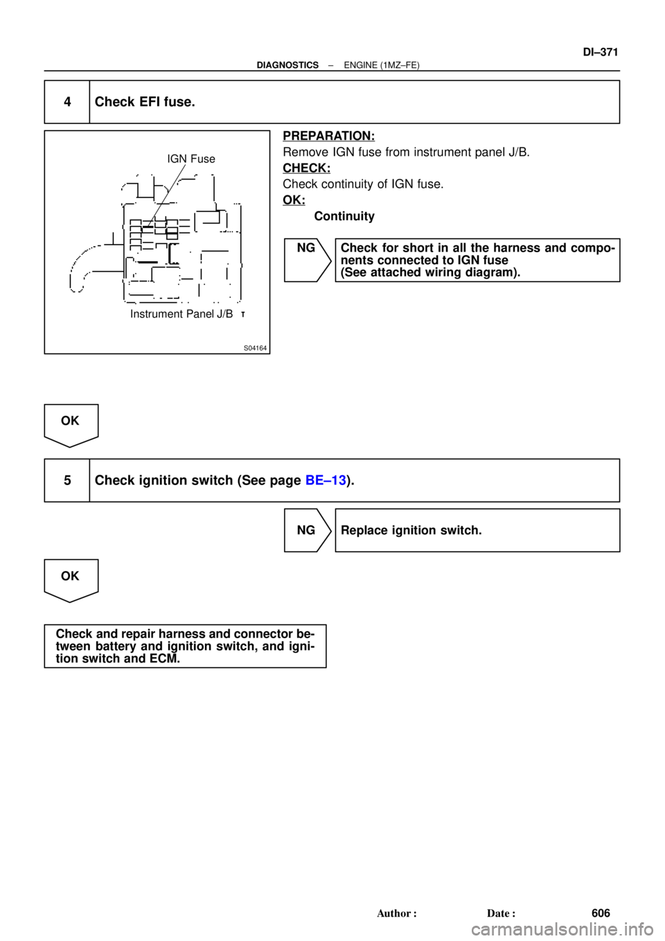
S04164
IGN Fuse
Instrument Panel J/B
± DIAGNOSTICSENGINE (1MZ±FE)
DI±371
606 Author�: Date�:
4 Check EFI fuse.
PREPARATION:
Remove IGN fuse from instrument panel J/B.
CHECK:
Check continuity of IGN fuse.
OK:
Continuity
NG Check for short in all the harness and compo-
nents connected to IGN fuse
(See attached wiring diagram).
OK
5 Check ignition switch (See page BE±13).
NG Replace ignition switch.
OK
Check and repair harness and connector be-
tween battery and ignition switch, and igni-
tion switch and ECM.
 Apply battery voltage between te")
.
Remove EFI fuse from J/B No.2.
Check continuity of EFI fuse.
Continuity")


Measure voltage between terminal BATT of en±
gine control module connector and body ground.
Voltage: 9 ±14 V
Check voltage between terminal BATT of engi")