Page 610 of 4770
Tube Type
ANTI±RUST TREATMENT
When replacing body panels, always apply body sealer, anti±rust agent or undercoat according to the re-
quirements of your country.
HINT: For further details, see the description given in Section AR of this manual.
BODY SEALER
Apply body sealer to the
required areas.ANTI±RUST AGENT (WAX)
Cartridge Type
Apply anti±rust agent to
following sections.
�Inside of the hems of the
doors and hood.
�Around the hinges of the
doors and hood.
�Inside of the welded parts
with boxed cross±section.
UNDERCOAT
Apply undercoat to the underbody and
wheel housings.
Spray Gun Undercoating
(Oil base)Undercoating
(Water base)
INTRODUCTIONIN-13
Page 693 of 4770
 to welding sur-
faces where the paint film has been removed.
HINT: Apply the weld±through primer (spot sealer)
so tha")
For anti±corrosion measures, always apply the
weld±through primer (spot sealer) to welding sur-
faces where the paint film has been removed.
HINT: Apply the weld±through primer (spot sealer)
so that it does not ooze out from the joining sur-
faces.
GENERAL INFORMATION
Anti±rust treatment is necessary before welding and before and after the painting process.
ANTI±RUST TREATMENT BEFORE WELDING
Weld±Through Primer
Spot Sealer
1. WELD±THROUGH PRIMER (SPOT SEALER) APPLICATION
WELD±THROUGH PRIMER (SPOT SEALER)
APPLICATION
ANTI±RUST TREATMENT BEFORE PAINTING PROCESS
1. BODY SEALER APPLICATION
For water±proofing and anti±corrosion measures,
always apply the body sealer to the body panel
seams and hems of the doors, hoods etc.Sealer Gun
BODY SEALER APPLICATION
2. UNDERCOAT APPLICATION
To prevent corrosion and protect the body from
damage by flying stones, always apply sufficient
undercoat to the bottom surface of the under body
and inside of the wheel housings.
UNDERCOAT APPLICATION ANTI±RUST TREATMENT
AR-2
Page 694 of 4770
 Anti±Chipping PaintSecond Coat
Steel Metal Undercoat (ED Primer) Second Coat Top Coat
ANTI±RUST TREATMENT AFTER PAINTING PROCESS
1. ANTI±RUST AGENT (WAX) APPLICATIO")
Steel MetalUndercoat (ED Primer) Anti±Chipping PaintSecond Coat
Steel Metal Undercoat (ED Primer) Second Coat Top Coat
ANTI±RUST TREATMENT AFTER PAINTING PROCESS
1. ANTI±RUST AGENT (WAX) APPLICATION
To preserve impossible to paint areas from corro-
sion, always apply sufficient anti±rust agent (wax)
to the inside of the hemming areas of the doors and
hoods, and around the hinges, or the welded sur-
faces inside the boxed cross±section structure of
the side member, body pillar, etc.
ANTI±RUST AGENT (WAX) APPLICATION
REFERENCE: ANTI±RUST TREATMENT BY PAINTING
Painting prevents corrosion and protects the sheet metal from damage. In this section, anti±chipping paint
only for anti±corrosion purpose is described.
1. ANTI±CHIPPING PAINT
To prevent corrosion and protect the body from damage by flying stones, etc., apply anti±chipping paint
to the rocker panel, wheel arch areas, valance panel, etc.
HINT:
Depending on the model or the application area, there are cases where the application of anti±chipping
paint is necessary before the second coat or after the top coat.
�Apply the anti±chipping paint
before the second coat. �Apply the anti±chipping paint
after the top coat.
Anti±Chipping Paint
Top Coat
ANTI±RUST TREATMENTAR-3
Page 1516 of 4770
AC2CL±01
I12253I12254
I12260
LH Lower Instrument
Panel
No.1 Lower Finish
Panel
Cowl Side Trim
Front Door Inside
Scuff PlateCenter Cluster Finish Panel
A/C Control Assembly
Glove Compartment
Cowl Side Trim
Mode Switch
A/C Switch
Defogger Switch
Heater Control
Name Sheet
Heater Control Knob Heater Control Base Blower Speed Control
SwitchFront Door Inside Scuff Plate
Air Intake Switch
AC±94± AIR CONDITIONINGAIR CONDITIONING CONTROL ASSEMBLY (Manual
A/C)
2582 Author�: Date�:
2001 CAMRY (RM819U)
COMPONENTS
Page 1517 of 4770
AC2CM±01
I12255
Air Mix Damper
Control Cable
I12256
± AIR CONDITIONINGAIR CONDITIONING CONTROL ASSEMBLY (Manual
A/C)AC±95
2583 Author�: Date�:
2001 CAMRY (RM819U)
REMOVAL
1. REMOVE COWL SIDE TRIM LH AND RH
2. REMOVE FRONT DOOR INSIDE SCUFF PLATE LH
AND RH
3. REMOVE NO. 2 LOWER COVER
4. REMOVE GLOVE COMPARTMENT
5. REMOVE NO. 1 LOWER INSTRUMENT PANEL
6. REMOVE LH LOWER INSTRUMENT PANEL
7. REMOVE CENTER CLUSTER FINISH PANEL
8. DISCONNECT AIR MIX DAMPER CONTROL CABLE
NOTICE:
When the air mix damper control cable is disconnected,
should not bend the cable.
9. REMOVE A/C CONTROL ASSEMBLY
Remove the 4 screws and pull out the A/C control assembly,
then disconnect the connector.
Page 1603 of 4770
AC0ND±02
Z19017
LH Lower Instrument
Panel
No.1 Lower Finish
Panel
Cowl Side Trim
Front Door Inside
Scuff PlateCenter Cluster Finish Panel
A/C Control Assembly
Glove Compartment
Cowl Side Trim
Air Inlet Damper Control Cable
Air Inlet Control Lever
Mode Switch
A/C Switch
Defogger Switch
Heater Control
Name Sheet
Heater Control Knob Heater Control BaseBlower Speed Control
SwitchFront Door Inside Scuff Plate
± AIR CONDITIONINGAIR CONDITIONING CONTROL ASSEMBLY
AC±81
2563 Author�: Date�:
COMPONENTS
Page 1604 of 4770
AC0NE±02
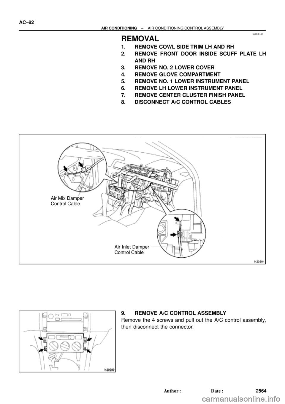
N20304
Air Mix Damper
Control Cable
Air Inlet Damper
Control Cable
N20289
AC±82
± AIR CONDITIONINGAIR CONDITIONING CONTROL ASSEMBLY
2564 Author�: Date�:
REMOVAL
1. REMOVE COWL SIDE TRIM LH AND RH
2. REMOVE FRONT DOOR INSIDE SCUFF PLATE LH
AND RH
3. REMOVE NO. 2 LOWER COVER
4. REMOVE GLOVE COMPARTMENT
5. REMOVE NO. 1 LOWER INSTRUMENT PANEL
6. REMOVE LH LOWER INSTRUMENT PANEL
7. REMOVE CENTER CLUSTER FINISH PANEL
8. DISCONNECT A/C CONTROL CABLES
9. REMOVE A/C CONTROL ASSEMBLY
Remove the 4 screws and pull out the A/C control assembly,
then disconnect the connector.
Page 2031 of 4770

BO0MB±01
N20950
Instrument Panel ReinforcementNN
DD
No.2 Instrumental Panel Bracket
No.1 Instrumental Panel Bracket
No.2 Instrumental Panel Brace
QQH N
N
N
N
GG
NG
NOB
NN
Instrument Panel Brace Mount
No.1 Instrument
Panel BraceFront Pillar Garnish
Front Pillar
GarnishFront
Passenger
Airbag
Assembly
20 (200, 14)
No.2 Side Defroster Nozzle
Cowl Side Trim
Front Door Openin
g
Cover
Instrument Panel
C
Remote Control
Mirror Hole Base
Upper Column
CoverHazard Warning
Switch
Lower Finish
PlateGlove Compartment
Door Finish PlateFront Door
Inside Scuff Plate
FFF
FJ
Glove
Compartment
No.2 Lower
Panel A
A
Cluster Finish
Panel
Lower Column
Cover
Front Door
Opening
Cover
Cowl Side
TrimD
DD
D
D
F
AA
Lower Panel
InsertCoin
BoxCombination SwitchCombination
MeterRadio Assembly
Center Cluster
Finish Panel
A/C
Control Assembly
35 (360, 26)
Steering
Wheel
Pad Steering Wheel No.1 Lower
Panel
Front Door
Inside Scuff PlateFront Console
Box
Center Console
Upper PanelF
F
B
B
Rear Console
Box
N´m (kgf´cm, ft´lbf) : Specified torque BO±72
± BODYINSTRUMENT PANEL
2420 Author�: Date�:
INSTRUMENT PANEL
COMPONENTS