Page 16 of 4770

CAMRY ± NEW FEATURES36
�5S-FNE ENGINE
1. Description
The 5S-FNE engine is a new engine that uses CNG (Compressed Natural Gas) as fuel, which has been devel-
oped based on the 5S-FE gasoline engine.
The main component of natural gas is methane (CH
4), which has fewer carbous (C) than gasoline (mean mo-
lecular formula: C
7.5H13.4). Therefore, the amount of CO2 discharged by this engine is approximately 70%
that of the gasoline engine. Furthermore, this engine achieves low-emission operation by precisely controlled
air-fuel ratio and using special catalysts for the CNG application.
However, because the fuel is in the gaseous form, its volumetric efficiency is low, causing lower power output
if this fuel is used in the base engine.
Therefore, the 5S-FNE engine has adopted the following features: a high compression ratio, the intake valves
with early closed timing, the intake and exhaust valves with increased lift, a low back pressure muffler made
possible by the 2-way exhaust system, injectors for gaseous fuel, and a catalytic converter designed exclu-
sively for CNG application. At the same time, precision air-fuel ratio control is effected through the use of
the air-fuel ratio sensor* and the heater oxygen sensor, thus achieving the level of performance that is equiva-
lent to the base engine. Moreover, this engine realizes extremely low emissions and restoring engine torque.
*: Already adopted on the California specification 5S-FE engine.
� Specifications �
Item5S-FNE Engine5S-FE Engine
No. of Cyls. & Arrangement4-Cylinder, In-Line�
Valve Mechanism16-Valve DOHC,
Belt & Gear Drive�
Combustion CamberPentroof Type�
ManifoldsCross-Flow�
Fuel SystemSFI�
Displacement cm3 (cu.in.)2164 (312.0)�
Bore x Stroke mm (in.)87.0 x 91.0 (3.43 x 3.58)�
Compression Ratio11.0 : 19.5 : 1
Max. Output [SAE-NET]88 kW @ 5200 rpm
(118 HP @ 5200 rpm)
101 kW @ 5200 rpm
(136 HP @ 5200 rpm)
97 kW @ 5200 rpm*
(133 HP @ 5200 rpm)*
Max. Torque [SAE-NET]178 N.m @ 2400 rpm
(131 ft-lbf @ 2400 rpm)
203 N.m @ 4400 rpm
(150 ft-lbf @ 4400 rpm)
201 N
.m @ 4400 rpm*
(148 ft-lbf @ 4400 rpm)*
IntakeOpen3� BTDC�
Valve
IntakeClose38� ABDC43� ABDCValve
Timing
ExhaustOpen45� BBDC�ExhaustClose3� AT D C�
Fuel Octane Number RON13091
Oil GradeAPI SJ EC or ILSAC�
*: California Specification Models
Page 21 of 4770

3
CAMRY ± NEW FEATURES
167CN05
WU-TWC
167CN06
TWCSub MufflerMain Muffler41
5. Intake and Exhaust System
Throttle Body
The throttle body is basically the same as that of the 5S-FE engine. However, to ensure the starting perfor-
mance at low temperatures, the air passage for the IAC (Idle Air Control) has been increased on the 5S-FNE
engine. The IAC valve is a 1-coil type with a built-in driver.
Exhaust Manifold
As in the California specification 5S-FE engine,
the stainless steel exhaust manifold and WU-
TWC (Warm Up Three-Way Catalytic Convert-
er) have been integrated to improve the warm-up
performance of TWC, thus reducing exhaust
emissions.
However, the 5S-FNE engine uses a catalytic
converter that has been designed exclusively for
the CNG application, in which the loading of the
noble metal has been increased.
Exhaust Pipe
1) General
�To secure sufficient luggage compartment capacity, the main muffler has been relocated below the rear
seat. Furthermore, the muffler capacity has been increased.
�A 2-way exhaust control system has been adopted to improve engine performance and reduce the exhaust
noise.
�Similar to the WU-TWC, the TWC (Three-Way Catalytic Converter) has been designed exclusively for
the CNG application, in which the loading of the noble metal has been increased.
Page 33 of 4770

3
CAMRY ± NEW FEATURES
172CM18
172CM19
ON
OFF1 sec 1 sec
1 sec 1 sec
ON
OFF1 sec 1 sec
2 sec 2 sec 2 sec53
Injector Control
1) General
Fuel clearing control and injector unsticking control have been added to the injector control.
2) Fuel Clearing Control
While the vehicle is being driven at speeds higher than 60 km / h (37.5 mph), and the ignition switch is
turned OFF after the ECM has detected a low temperature condition of less than 25�C (77�F) of intake
air temperature, the ECM closes the fuel shutoff valve for the delivery pipe. However, instead of immedi-
ately stopping the engine, the fuel clearing control allows the engine to stop on its own after the fuel in
the delivery pipe has been used up. If the engine is running even after 2 seconds or more have elapsed
after the ignition switch has been turned OFF, the EFI relay is turned OFF to stop the engine.
3) Injector Unsticking Control
When the ignition switch is turned ON after executing the fuel clearing control, the injector unsticking
control activates two cylinders at a time to unstick the valve that is frozen stuck onto the valve seat. At
low temperature conditions. At this time, the shutoff valve remains closed so that the injectors will not
inject fuel.
Gas Leak Judgment
�If the ECM has detected a gas leak through the signals received from the pressure sensors, the ECM closes
the shutoff valves and flashes the low fuel level warning light.
�These functions are canceled by resetting the ECM (by disconnecting the negative [-] terminal of the bat-
tery), which enables the engine to start.
(The ECM should be reset only after performing a gas leak check and making sure that the leak has been
eliminated.)
NOTE: The low fuel level warning light also flashes when the fuel level is extremely low. The flashing
patterns shown below differentiates a gas leak from a low fuel level.
Flashing Pattern
Gas Leak
Fuel Low Level
Page 100 of 4770

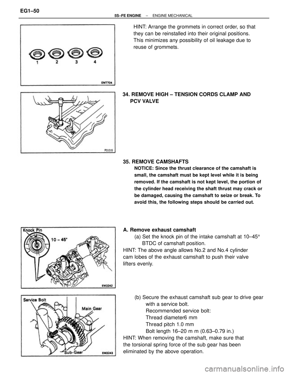
(b) Secure the exhaust camshaft sub gear to drive gear
with a service bolt.
Recommended service bolt:
Thread diameter6 mm
Thread pitch 1.0 mm
Bolt length 16±20 m m (0.63±0.79 in.)
HINT: When removing the camshaft, make sure that
the torsional spring force of the sub gear has been
eliminated by the above operation. 35. REMOVE CAMSHAFTS
NOTICE: Since the thrust clearance of the camshaft is
small, the camshaft must be kept level while it is being
removed. If the camshaft is not kept level, the portion of
the cylinder head receiving the shaft thrust may crack or
be damaged, causing the camshaft to seize or break. To
avoid this, the following steps should be carried out.
A. Remove exhaust camshaft
(a) Set the knock pin of the intake camshaft at 10±455
BTDC of camshaft position.
HINT: The above angle allows No.2 and No.4 cylinder
cam lobes of the exhaust camshaft to push their valve
lifters evenly.HINT: Arrange the grommets in correct order, so that
they can be reinstalled into their original positions.
This minimizes any possibility of oil leakage due to
reuse of grommets.
34. REMOVE HIGH ± TENSION CORDS CLAMP AND
PCV VALVE
± 5S±FE ENGINEENGINE MECHANICALEG1±50
Page 222 of 4770

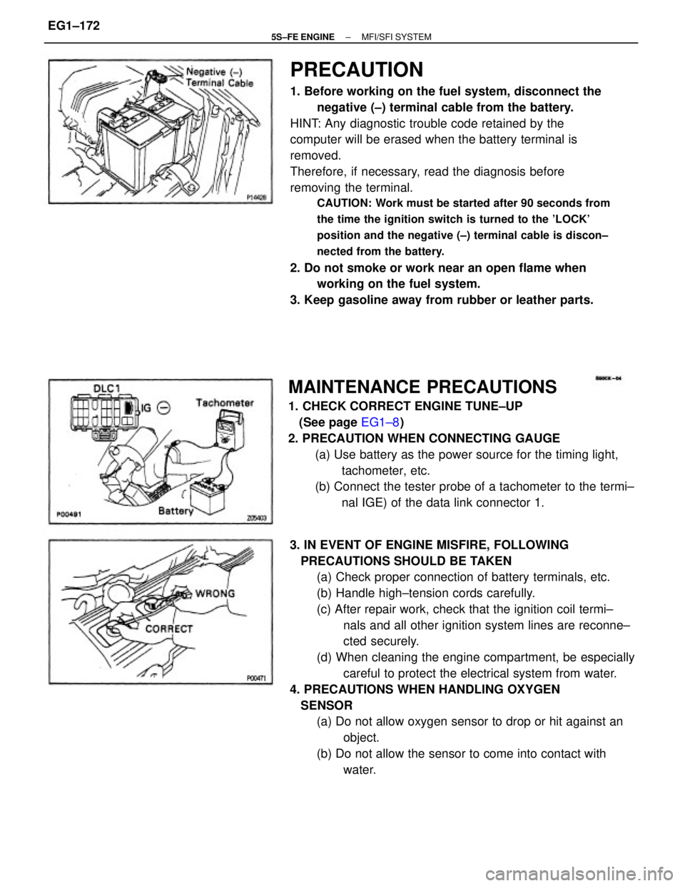
PRECAUTION
1. Before working on the fuel system, disconnect the
negative (±) terminal cable from the battery.
HINT: Any diagnostic trouble code retained by the
computer will be erased when the battery terminal is
removed.
Therefore, if necessary, read the diagnosis before
removing the terminal.
CAUTION: Work must be started after 90 seconds from
the time the ignition switch is turned to the 'LOCK'
position and the negative (±) terminal cable is discon±
nected from the battery.
2. Do not smoke or work near an open flame when
working on the fuel system.
3. Keep gasoline away from rubber or leather parts.
3. IN EVENT OF ENGINE MISFIRE, FOLLOWING
PRECAUTIONS SHOULD BE TAKEN
(a) Check proper connection of battery terminals, etc.
(b) Handle high±tension cords carefully.
(c) After repair work, check that the ignition coil termi±
nals and all other ignition system lines are reconne±
cted securely.
(d) When cleaning the engine compartment, be especially
careful to protect the electrical system from water.
4. PRECAUTIONS WHEN HANDLING OXYGEN
SENSOR
(a) Do not allow oxygen sensor to drop or hit against an
object.
(b) Do not allow the sensor to come into contact with
water.
MAINTENANCE PRECAUTIONS
1. CHECK CORRECT ENGINE TUNE±UP
(See page EG1±8)
2. PRECAUTION WHEN CONNECTING GAUGE
(a) Use battery as the power source for the timing light,
tachometer, etc.
(b) Connect the tester probe of a tachometer to the termi±
nal IGE) of the data link connector 1.
± 5S±FE ENGINEMFI/SFI SYSTEMEG1±172
Page 224 of 4770
(b) Insert the test probe into the connector from wiring
side when checking the continuity, amperage or volt±
age.
(c) Do not apply unnecessary force to the terminal.
(d) After checking, install the water±proofing rubber on
the connector securely. 8. Care is required when pulling out and inserting wiring
connectors.
(a) Release the lock and pull out the connector, pulling on
the connectors.
9. When inspecting a connector with a volt/ohmmeter.
(a) Carefully take out the water±proofing rubber if it is a
water±proof type connector.
10. Use SST for inspection or test of the injector or its
wiring connector.
SST 09842±30070 (b) Fully insert the connector and check that it is locked.
± 5S±FE ENGINEMFI/SFI SYSTEMEG1±174
Page 259 of 4770

(b) Apply vacuum to the throttle opener.
(c) Insert a 0.60 mm (0.024 in.) thickness gauge between
the throttle stop screw and stop lever.
(d) Connect the test probe of an ohmmeter to the termi±
nals IDL and E2 of the sensor.
(e) Gradually turn the sensor clockwise until the ohmmeter
deflects, and secure it with the 2 set screws. 3. INSPECT THROTTLE POSITION SENSOR
(a) Apply vacuum to the throttle opener.
(b) Insert a thickness gauge between the throttle stop
screw and stop lever.
(c) Using an ohmmeter, measure the resistance between
each terminal. 2. INSPECT THROTTLE VALVE
(a) Apply vacuum to the throttle opener.
(b) Check that there is no clearance between the throttle
stop screw and throttle lever when the throttle valve
is fully closed.
4. IF NECESSARY, ADJUST THROTTLE POSITION
SENSOR
(a) Loosen the 2 set screws of the sensor.
Clearance between
lever and stop screw
Throttle valve fully
open 0.50 mm (0.020 in.)
0.70 mm (0.028 in.)Between terminals
2.0 ± 10.2 k� 2.3 k� or less 0.2 ± 5.7 k�
0 mm (0 in.)
2.5 ± 5.9 k� Resistance
VTA ± E2
VTA ± E2IDL±E2IDL±E2
Infinity
VC ± E2
± 5S±FE ENGINEMFI/SFI SYSTEMEG1±209
Page 345 of 4770
CUSTOMER PROBLEM ANALYSIS CHECK SHEET
± 5S±FE ENGINECUSTOMER PROBLEM ANALYSIS CHECK SHEETEG1±295