Page 231 of 4770

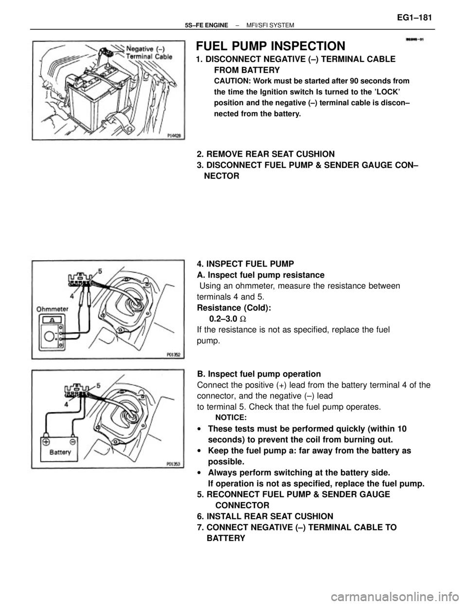
B. Inspect fuel pump operation
Connect the positive (+) lead from the battery terminal 4 of the
connector, and the negative (±) lead
to terminal 5. Check that the fuel pump operates.
NOTICE:
wThese tests must be performed quickly (within 10
seconds) to prevent the coil from burning out.
wKeep the fuel pump a: far away from the battery as
possible.
wAlways perform switching at the battery side.
If operation is not as specified, replace the fuel pump.
5. RECONNECT FUEL PUMP & SENDER GAUGE
CONNECTOR
6. INSTALL REAR SEAT CUSHION
7. CONNECT NEGATIVE (±) TERMINAL CABLE TO
BATTERY
FUEL PUMP INSPECTION
1. DISCONNECT NEGATIVE (±) TERMINAL CABLE
FROM BATTERY
CAUTION: Work must be started after 90 seconds from
the time the Ignition switch Is turned to the 'LOCK'
position and the negative (±) terminal cable is discon±
nected from the battery.
4. INSPECT FUEL PUMP
A. Inspect fuel pump resistance
Using an ohmmeter, measure the resistance between
terminals 4 and 5.
Resistance (Cold):
0.2±3.0 W
If the resistance is not as specified, replace the fuel
pump. 2. REMOVE REAR SEAT CUSHION
3. DISCONNECT FUEL PUMP & SENDER GAUGE CON±
NECTOR
± 5S±FE ENGINEMFI/SFI SYSTEMEG1±181
Page 234 of 4770
FUEL PUMP DISASSEMBLY
1. REMOVE FUEL PUMP FROM FUEL PUMP BRACKET
(a) Remove the fuel pump lead wire.
(b) Pull off the lower side of the fuel pump from the pump
bracket.
(c) Disconnect the fuel hose from the fuel pump, and
remove the fuel pump.
(d) Remove the rubber cushion from the fuel pump.
2. REMOVE FUEL SENDER GAUGE FROM FUEL PUMP
BRACKET
(a) Disconnect the fuel sender gauge connector.
(b) Remove the 2 screws and sender gauge.
COMPONENTS FOR DISASSEMBLY AND
ASSEMBLY
± 5S±FE ENGINEMFI/SFI SYSTEMEG1±184
Page 235 of 4770
FUEL PUMP ASSEMBLY
(See Components for Disassembly and Assembly)
1. INSTALL CONNECTOR
Install the gasket, connector and connector support
with the 2 screws.
2. INSTALL FUEL PUMP FILTER TO FUEL PUMP
Install the pump filter with a new clip.
4. INSTALL FUEL PUMP TO FUEL PUMP BRACKET
(a) Install the rubber cushion to the fuel pump.
(b) Connect the fuel hose to the outlet port of the fuel
pump.
(c) Install the fuel pump by pushing the lower side of the
fuel pump.
(d) Install the fuel pump connector. 3. INSTALL FUEL SENDER GAUGE TO FUEL PUMP
BRACKET
(a) Install the sender gauge with the 2 screws.
(b) Connect the fuel sender gauge connector. 4. REMOVE CONNECTOR
Remove the 2 screws, connector support, connector
and gasket. 3. REMOVE FUEL PUMP FILTER FROM FUEL PUMP
(a) Using a small screwdriver, remove the clip.
(b) Pull out the pump filter.
± 5S±FE ENGINEMFI/SFI SYSTEMEG1±185
Page 236 of 4770
2. CONNECT FUEL PIPE AND HOSE TO FUEL PUMP
BRACKET
(a) Using SST, connect the outlet pipe to the pump
bracket.
SST 09631±22020
Torque: 28 N±m (285 kgf±cm, 21 ft±lbf)
(b) Connect the return hoses to the pump bracket.
3. CHECK FOR FUEL LEAKAGE
(See page EG1±176)
4. CONNECT FUEL PUMP LEAD WIRE
5. INSTALL FLOOR SERVICE HOLE COVER
(a) Install the service hole cover with the 5 screws.
(b) Connect the fuel pump (with fuel sender gauge)
connector.
FUEL PUMP INSTALLATION
(See Components for Removal and Installation)
1. INSTALL FUEL PUMP BRACKET ASSEMBLY TO
FUEL TANK
(a) Install a new gasket to the pump bracket.
(b) Insert the pump bracket assembly into the fuel tank.
6. INSTALL REAR SEAT CUSHION
7. CONNECT NEGATIVE (±) TERMINAL CABLE TO
BATTERY(c) Install the pump bracket with the 8 screws.
Torque: 3.9 N±m (40 kgf±cm, 35 in.±Ibf)
± 5S±FE ENGINEMFI/SFI SYSTEMEG1±186
Page 1157 of 4770

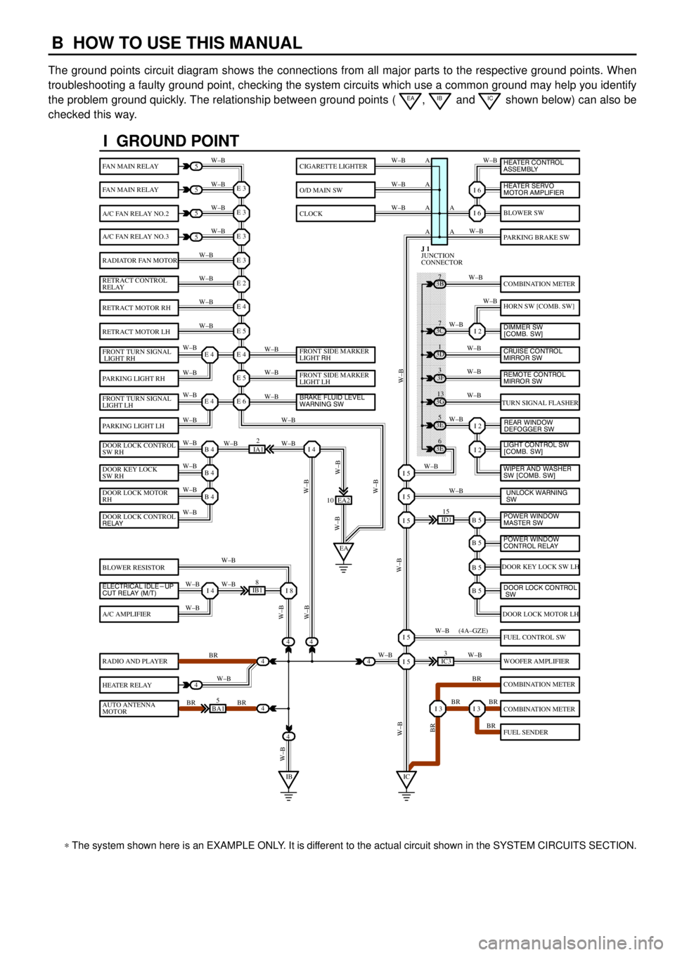
B HOW TO USE THIS MANUAL
The ground points circuit diagram shows the connections from all major parts to the respective ground points. When
troubleshooting a faulty ground point, checking the system circuits which use a common ground may help you identify
the problem ground quickly. The relationship between ground points (
EA, IB and IC shown below) can also be
checked this way.
���� ���� ���� ���� ���� ���� ���� ���� ���� ���� ���� ���� ���� ���� ���� ���� ���� ���� ����
I GROUND POINT
FAN MAIN RELAY
FAN MAIN RELAY
A/C FAN RELAY NO.2
A/C FAN RELAY NO.3
RADIATOR FAN MOTOR
RETRACT CONTROL
RELAY
RETRACT MOTOR RH
RETRACT MOTOR LH
FRONT TURN SIGNAL
LIGHT RH
PARKING LIGHT RH
FRONT TURN SIGNAL
LIGHT LH
PARKING LIGHT LH
DOOR LOCK CONTROL
SW RH
DOOR KEY LOCK
SW RH
DOOR LOCK MOTOR
RH
BLOWER RESISTOR
A/C AMPLIFIER
RADIO AND PLAYER
HEATER RELAY
AUTO ANTENNA
MOTOR
BLOWER SW
PARKING BRAKE SW
COMBINATION METER
HORN SW [COMB. SW]
TURN SIGNAL FLASHER
DOOR KEY LOCK SW LH
DOOR LOCK MOTOR LH
FUEL CONTROL SW
WOOFER AMPLIFIER
COMBINATION METER
COMBINATION METER
FUEL SENDER
CIGARETTE LIGHTER
O/D MAIN SW
CLOCK
5
5
5
5
4
4
4
4
4BA15
IB18
EA2 10
3E5
3E
6 3G
13 3F
3 3D
1 3B
7
ID115
IC33
IA12
E 3
A
A AW±B
W±BW±B W±B
W±B W±B
W±B
W±B
W±B
W±B
W±B
W±B
W±B
W±B
W±B W±BW±B W±B W±B W±B
W±B W±B
W±BW±B
W±B
W±B
W±B W±B
W±B
BR
W±B
BR BRW±BW±B
W±B
W±B
W±B
W±B
W±B
W±B
W±B
W±B
W±B W±B
W±B
W±B
W±B
W±B
BR W±B
BR BR
BR W±B W±BW±B
W±BW±BBR W±B (4A±GZE)
W±B A A A
I 6
I 6
I 2
I 2
I 2
B 5I 5
I 5
I 5
B 5
B 5
B 5
I 5
I 5
I 3I 3
E 3
E 3
E 3
E 2
E 4
E 5
E 4
E 5
E 6E 4
E 4
B 4
EAI 4
B 4
B 4
I 4I 8
IBIC
3C7
4
JUNCTION
CONNECTOR J 1
4
DOOR LOCK CONTROL
RELAY
ELECTRICAL IDLE-UP
CUT RELAY (M/T)FRONT SIDE MARKER
LIGHT RH
FRONT SIDE MARKER
LIGHT LH
BRAKE FLUID LEVEL
WARNING SW
UNLOCK WARNING
SW WIPER AND WASHER
SW [COMB. SW] LIGHT CONTROL SW
[COMB. SW] HEATER CONTROL
ASSEMBLY
HEATER SERVO
MOTOR AMPLIFIER
DIMMER SW
[COMB. SW]
CRUISE CONTROL
MIRROR SW
REAR WINDOW
DEFOGGER SW
POWER WINDOW
MASTER SW
POWER WINDOW
CONTROL RELAY
DOOR LOCK CONTROL
SW
REMOTE CONTROL
MIRROR SW
* The system shown here is an EXAMPLE ONLY. It is different to the actual circuit shown in the SYSTEM CIRCUITS SECTION.
Page 1181 of 4770

G ELECTRICAL WIRING ROUTING
Position of Parts in Body
A 25 ABS Speed Sensor Rear LH
A 26 ABS Speed Sensor Rear RH
A 27 Auto Antenna Motor and Relay
B 6 Buckle SW LH
C 16 Condenser
D 12 Door Courtesy SW Front LH
D 13 Door Courtesy SW Front RH
D 14 Door Courtesy SW Rear LH
D 15 Door Courtesy SW Rear RH
D 16 Door Key Lock and Unlock SW Front LH
D 17 Door Key Lock and Unlock SW Front RH
D 18 Door Lock Control SW RH
D 19 Door Lock Motor and Door Unlock Detection SW Front LH
D 20 Door Lock Motor and Door Unlock Detection SW Front RH
D 21 Door Lock Motor and Door Unlock Detection SW Rear LH
D 22 Door Lock Motor and Door Unlock Detection SW Rear RHF 10 Front Door Speaker LH
F 11 Front Door Speaker RH
F 12 Front Tweeter (Speaker) LH
F 13 Front Tweeter (Speaker) RH
F 14 Fuel Pump and Sender
H 10 High Mounted Stop Light
I 19 Interior Light
J 38 Junction Connector
J 39 Junction Connector
J 40 Junction Connector
L 1 License Plate Light LH
L 2 License Plate Light RH
L 3 Light Failure Sensor
L 4 Luggage Compartment Key Unlock SW
L 5 Luggage Compartment Light
L 6 Luggage Compartment Light SW
Page 1427 of 4770
COMBINATION METER
10A
GAUGEFROM POWER SOURCE SYSTEM (
SEE PAGE 50)
1D 27. 5A
DOME
2J 12
1J 1
1G 81W 1
IF2 3IF24IJ17IJ12IJ13IJ16 IG3 6IG3 10 C 7B 14 B11
B 6B3C5C8B15 C6B10 A2A1C2
FUEL
TACHO
SPEEDOMETER
WATER TEMP.
1 II2 2IG33
IF2 1
IH1 JUNCTION
CONNECTOR J 4
JUNCTION
CONNECTOR J28
FUEL SENDER F1 4JUNCTION
CONNECTOR J15JUNCTION
CONNECTOR J1 6
WATER
TEMP.
SENDER W 3
VEHICLE SPEED SENSOR
(
COMBINATION METER) V 2
JUNCTION
CONNECTOR J24
FROM ENGI NE
CONTROL MODULE
TO DOOR
COURTESY SW
TO ENGI NE
CONTROL MODULETO ENGI NE
CONTROL MODULE
TO CRUISE
CONTROL ECU R±L
R±L R±L
V±W
V±W V±W
R R±L R±L
Y±R
G±WY±R
G±W
BR
B±O
L
P
R±W
BR
Y±G
G± R BR BR
BR
B±O
L
P R±L
BR BR
Y±G
G± R
R±L
V±W
R±L FF
DB
232B
DBEE
3
1
FUEL
DOOR
MALFUNCTION
INDICATOR LAMPTRIP METER
ODOMETER
SI SE
IG+
ED : * 1
EC : * 221
DIODE
(
DOME) D10
R±YR R
J21(
*2)
(
*1)
AA C 8
COMBINATION METERB A, C 9 C, C10
TO A/C CONTROL
AS SE MB LY V±W
,
Page 1456 of 4770

REMOTE CONTROL
MIRROR SW
O/D MAIN SW
SHIFT LOCK ECU
COMBINATION
METER
CLOCK
GLOVE BOX LIGHT
AND SW
RHEOSTATWIRELESS DOOR LOCK
ECU
THEFT DETERRENT
ECU
DOOR KEY LOCK AND
UNLOCK SW FRONT RH
DOOR LOCK MOTOR
AND DOOR UNLOCK
DETECTION SW
FRONT RH
DOOR LOCK CONTROL
SW RH
REMOTE CONTROL
MIRROR RH
FUEL SENDER
COMBINATION
METER
AUTO ANTENNA MOTOR
AND RELAY STEREO COMPONENT
AMPLIFIER
RADIO AND PLAYER
DOOR LOCK MOTOR
AND DOOR UNLOCK
DETECTION SW
REAR RH
POWER SEAT
CONTROL SW
(
FRONT PASSENGER' S
SEAT)(
±)
(
EP)
A
A A A A A A A A AA
A
A
A
A
A
IF IJ W± B
W± B
W± B
W± B
W± B
W± B
W± B
W± BW±B
W±B
W±B
W±B W± B W± B
W±B
W±B W±BW±B
IHIF21
IH17
B 6
B 6 BR11 BP16
IK BN W±B
W±BW± B
W± BW±BBR
BR BR
BR
W±B W±B
W±B
BR
JUNCTION
CONNECTOR J 5JUNCTION
CONNECTOR J39
* 1 : TMC MADE
* 2 : TMMK MADE
* 3 : W/ TRACTI ON CONTROL
* 5 : W/ DAYTIME RUNNING LIGHT
* 7 : W/O MOON ROOF
* 8 : W/O THEFT DETERRENT SYSTEMIM1 20
(
ES) BR
BR * 9 : AUTOMATIC A/CDOOR KEY LOCK AND
UNLOCK SW FRONT RH
DOOR LOCK MOTOR
AND DOOR UNLOCK
DETECTION SW
FRONT RH
DOOR LOCK CONTROL
SW RH
REMOTE CONTROL
MIRROR RH W± B
W± B
W± B
W± B B1 4 W±B(
*1)
(
*1)
(
*1)
(
*1)
(
*2)
(
*2)
(
*2)
(
*2) (
*2)
* 6 : W/ MOON ROOF