Page 3534 of 4770

EGR Gas Temperature
Sensor Connector
Water Bypass Hose
A06657
PS Pressure TubeAir Intake Chamber Stay
V±Bank Cover
VSV Connector
for EGR
Engine Wire�Gasket
No.2 EGR Pipe
Throttle Position
Sensor Connector
Vacuum Hose
EGR Valve Position Brake Booster12 (120,9)
39 (400,29)
�Gasket
Sensor Connector
IAC Valve
ConnectorAccelerator Cable
Throttle Cable
Purge Hose
Air Assist Hose Hose Vacuum
�Gasket
VSV Connector for ACIS
Engine Coolant
Reservoir Hose
43 (440,32)
ECT Sender
Gauge Connector
ECT Sensor
Connector
Grand Strap
Connector
15 (150,11)
Water Outlet
15 (150,11)
Water Bypass
Hose
Upper Radiator
Hose
Fuel Inlet Hose
Injector Connector Intake Manifold Assembly�Retainer
Heater Hose
�Gasket Ignition Coil
Connector
� Non±reusable part: Specified torque
N´m (kgf´cm, ft´lbf)
19.5 (200, 14)
No.1 Engine
Hanger
VSV Connector for
EVAP
Ground Cable
PCV Hose Ground Cable
Air Intake Chamber
Assembly
� Gasket
High±Tension Cord Set
Spark PlugIgnition Coil
Water Bypass Hose
Ground Strap
DLC1
EM±28
± ENGINE MECHANICAL (1MZ±FE)CYLINDER HEAD
1314 Author�: Date�:
Page 3954 of 4770
PP0L0±01
± PREPARATIONBODY ELECTRICAL
PP±103
155 Author�: Date�:
EQUIPMENT
Voltmeter
Ammeter
Ohmmeter
Test lead
SyphonBrake fluid level warning switch
Bulb (3.4 W)Fuel sender gauge, Seat belt warning relay
Bulb (21 W)Turn signal flasher relay
Dry cell batteryFuel sender gauge
Torque wrench
Masking tapeRear window defogger wire
Tin foilRear window defogger wire
Page 4029 of 4770

USA:
Standard indicat")
SS0B0±05
± SERVICE SPECIFICATIONSBODY ELECTRICAL
SS±67
230 Author�: Date�:
BODY ELECTRICAL
SERVICE DATA
TURN SIGNAL FLASHER
Flashes/ Minute60 ± 120
SPEEDOMETER (ON±VEHICLE)
USA:
Standard indication (mph)Allowable range (mph)
2018 ± 24
4038 ± 44
6056 ± 66
8078 ± 88
10098 ± 110
120118 ± 132
CANADA:
Standard indication (km/h)Allowable range (km/h)
2017 ± 24
4038 ± 46
6057.5 ± 67
8077 ± 88
10096 ± 109
120115 ± 130
140134 ± 151.5
160153 ± 173
TACHOMETER (ON±VEHICLE)/ DC 13.5 V 25 °C at (77 °F)
Standard indicationAllowable range
700630 ± 770
1,000900 ± 1,100
2,0001,850 ± 2,150
3,0002,800 ± 3,200
4,0003,800 ± 4,200
5,0004,800 ± 5,200
6,0005,750 ± 6,250
7,0006,700 ± 7,300
FUEL RECEIVER GAUGE
A ± BApprox. 126.2 W
A ± CApprox. 280.5 W
B ± CApprox. 154.3 W
FUEL SENDER GAUGE
Float position mm (in.)Resistance (W)
F: Approx. ±91.1 (±3.587)Approx. 3.0
1/2: Approx. ±34.2 (±1.346)Approx. 31.7
E: Approx. 30.8 (1.213)Approx. 110.0
ENGINE COOLANT TEMPERATURE RECEIVER GAUGE (Resistance)
A ± BApprox. 175.7 W
A ± CApprox. 54.0 W
Page 4041 of 4770
GasketSST (Union Bolt)
SST
(Gauge)
Gasket
S04508
Ohmmeter
4
5
± SFI (5S±FE)FUEL PUMP
SF±7
1440 Author�: Date�:
(d) Install the fuel inlet hose and SST (pres")
S05328
Fuel Inlet
Hose
Gasket
SST (Union)GasketSST (Union Bolt)
SST
(Gauge)
Gasket
S04508
Ohmmeter
4
5
± SFI (5S±FE)FUEL PUMP
SF±7
1440 Author�: Date�:
(d) Install the fuel inlet hose and SST (pressure gauge) to the
fuel filter outlet with the 3 gaskets and SST (union bolt).
SST 09268±45014 (09268±41190, 90405±06167)
Torque: 29 N´m (300 kgf´cm, 21 ft´lbf)
(e) Wipe off any splattered gasoline.
(f) Reconnect the negative (±) terminal cable to the battery.
(g) Connect a TOYOTA hand±held tester to the DLC3.
(See step 1 in check fuel pump operation (a) to (e))
(h) Measure the fuel pressure.
Fuel pressure:
301 ± 347 kPa (3.1 ± 3.5 kgf/cm
2, 44 ± 50 psi)
If pressure is high, replace the fuel pressure regulator.
If pressure is low, check the fuel hoses, fuel hose connections,
fuel pump, fuel filter and fuel pressure regulator.
(i) Disconnect the TOYOTA hand±held tester from the
DLC3.
(j) Start the engine.
(k) Measure the fuel pressure at idle.
Fuel pressure:
301 ± 347 kPa (3.1 ± 3.5 kgf/cm
2, 44 ± 50 psi)
(l) Stop the engine.
(m) Check that the fuel pressure remains as specified for 5
minutes after the engine has stopped.
Fuel pressure:
147 kPa (1.5 kgf/cm
2, 21 psi) or more
If pressure is not as specified, check the fuel pump, pressure
regulator and/or injectors.
(n) After checking fuel pressure, disconnect the negative (±)
terminal cable from the battery and carefully remove the
SST to prevent gasoline from splashing.
SST 09268±45014
(o) Reconnect the fuel inlet hose with 2 new gaskets and the
union bolt.
Torque: 29 N´m (300 kgf´cm, 21 ft´lbf)
(p) Reconnect the negative (±) terminal cable to the battery.
(q) Check for fuel leaks. (See page SF±1)
3. REMOVE REAR SEAT CUSHION
4. REMOVE FLOOR SERVICE HOLE COVER
5. DISCONNECT FUEL PUMP & SENDER GAUGE CON-
NECTOR
6. INSPECT FUEL PUMP RESISTANCE
Using an ohmmeter, measure the resistance between terminals
4 and 5.
Resistance: 0.2 ± 3.0 W at 20°C (68°F)
If the resistance is not as specified, replace the fuel pump.
Page 4042 of 4770
S04509Battery4
5 SF±8
± SFI (5S±FE)FUEL PUMP
1441 Author�: Date�:
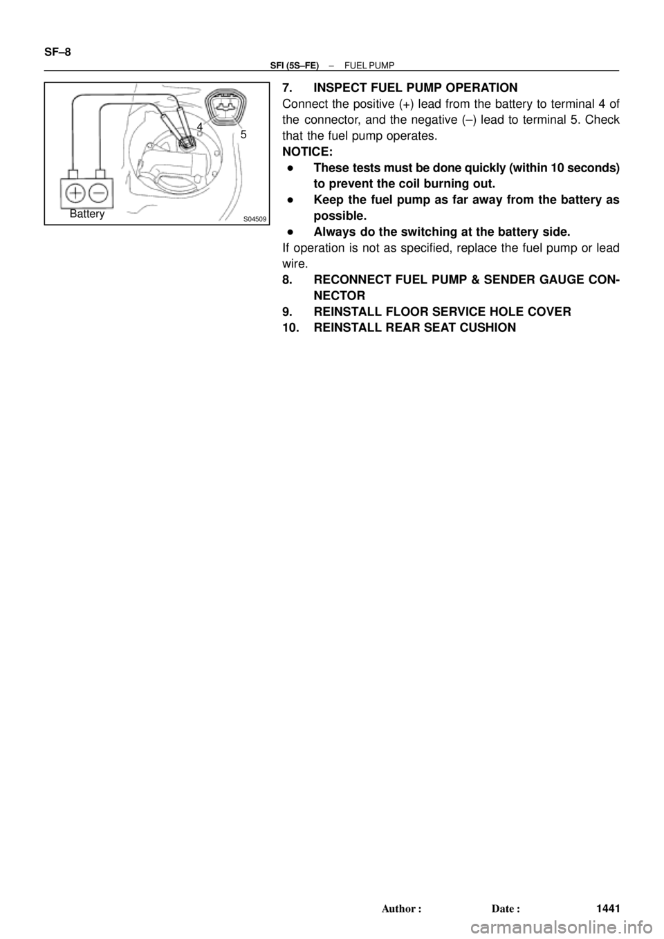
7. INSPECT FUEL PUMP OPERATION
Connect the positive (+) lead from the battery to terminal 4 of
the connector, and the negative (±) lead to terminal 5. Check
that the fuel pump operates.
NOTICE:
�These tests must be done quickly (within 10 seconds)
to prevent the coil burning out.
�Keep the fuel pump as far away from the battery as
possible.
�Always do the switching at the battery side.
If operation is not as specified, replace the fuel pump or lead
wire.
8. RECONNECT FUEL PUMP & SENDER GAUGE CON-
NECTOR
9. REINSTALL FLOOR SERVICE HOLE COVER
10. REINSTALL REAR SEAT CUSHION
Page 4043 of 4770
SF0D8±02
Z19025
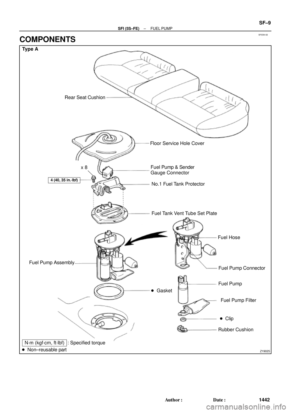
Type A
Rear Seat Cushion
� Gasket
4 (40, 35 in.´lbf)
Floor Service Hole Cover
Fuel Pump & Sender
Gauge Connector
No.1 Fuel Tank Protector
Fuel Tank Vent Tube Set Plate
Fuel Hose
Fuel Pump Connector
Fuel Pump
Fuel Pump Filter
� Clip
Rubber Cushion Fuel Pump Assembly
N´m (kgf´cm, ft´lbf)
� Non±reusable part: Specified torquex 8
± SFI (5S±FE)FUEL PUMP
SF±9
1442 Author�: Date�:
COMPONENTS
Page 4044 of 4770
S06038
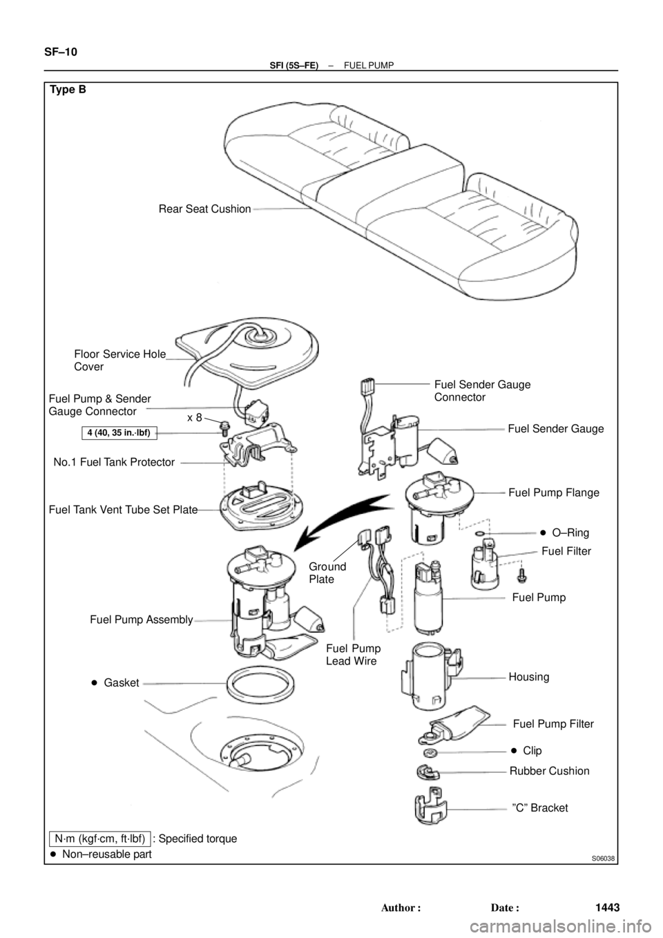
Type B
Rear Seat Cushion
� Gasket
4 (40, 35 in.´lbf)
Floor Service Hole
Cover
Fuel Pump & Sender
Gauge Connector
No.1 Fuel Tank Protector
Fuel Tank Vent Tube Set Plate
Fuel Filter Fuel Pump Flange
Fuel Pump
Fuel Pump Filter
� Clip
Rubber Cushion Fuel Pump Assembly
N´m (kgf´cm, ft´lbf)
� Non±reusable part� O±Ring
Housing
ºCº Bracket Fuel Sender Gauge
Fuel Pump
Lead Wire
: Specified torqueFuel Sender Gauge
Connector
Ground
Plate
x 8
SF±10
± SFI (5S±FE)FUEL PUMP
1443 Author�: Date�:
Page 4045 of 4770
FUEL PUMP
SF±11
1444 Author�: Date�:
REMOVAL
CAUTION:
Do not smoke or work near an open flame when working on
the fuel pump.
1. REMOVE REAR SEAT CUSHI")
SF0D9±03
S04583
S04592
Vinyl Bag
± SFI (5S±FE)FUEL PUMP
SF±11
1444 Author�: Date�:
REMOVAL
CAUTION:
Do not smoke or work near an open flame when working on
the fuel pump.
1. REMOVE REAR SEAT CUSHION
2. REMOVE FLOOR SERVICE HOLE COVER
(a) Take out the floor carpet.
(b) Remove the service hole cover.
HINT:
At the time of installation, please refer to the following items.
Check for fuel leakage.
3. DISCONNECT FUEL PUMP & SENDER GAUGE CON-
NECTOR
4. REMOVE NO.1 FUEL TANK PROTECTOR
Remove the 2 bolts and No.1 fuel tank protector.
Torque: 4 N´m (40 kgf´cm, 35 in.´lbf)
5. DISCONNECT FUEL TUBE (FUEL TUBE CONNEC-
TOR)
CAUTION:
�Perform disconnecting and connecting operations of
the fuel tube connector (quick type) after observing
the precautions.
�As there is retained pressure in the fuel pipe line, pre-
vent it from splashing inside the vehicle compart-
ment.
6. REMOVE FUEL PUMP ASSEMBLY FROM FUEL TANK
(a) Remove the 6 bolts and fuel tank vent tube set plate.
Torque: 4 N´m (40 kgf´cm, 35 in.´lbf)
(b) Pull out the fuel pump assembly.
(c) Remove the gasket from the pump assembly.
NOTICE:
�Do not damage the fuel pump filter.
�Be careful that the arm of the sender gauge should
not bent.
HINT:
At the time of installation, please refer to the following items.
Install a new gasket to the pump assembly.