Page 53 of 4770

The 5S±FE engine is an in±line, 4±cylinder engine with the cylinders numbered 1±2±3±4
from the front. The crankshaft is supported by five bearings inside the crankcase. These bearings
are made of aluminum alloy.
The crankshaft is integrated with eight weights for balance. Oil holes are placed in the center of
the crankshaft to supply oil to the connecting rods, bearing, pistons and other components.
The firing order is 1±3±4±2. The cylinder head is made of aluminum alloy, with a cross flow
type intake and exhaust layout and with pent±roof type combustion chambers. The spark plugs
are located in the center of the combustion chambers.
The intake manifold has four independent long ports and utilizes the inertial supercharging effect
to improve engine torque at low and medium speeds.
Exhaust and intake valves are equipped with irregular pitch springs made of special valve spring
carbon steel which are capable of functioning no matter what the engine speed.
The intake camshaft is driven by a timing belt, and a gear on the intake camshaft engages with
a gear on the exhaust camshaft to drive it. The cam journal is supported at five places between
the valve lifters of each cylinder and on the front end of the cylinder head. Lubrication of the cam
journals and gears is accomplished by oil being supplied through the oiler port in the center of the
camshaft.
Adjustment of the valve clearance is done by means of an outer shim type system, in which valve
adjusting shims are located above the valve lifters. This permits replacement of the shims without
removal of the camshafts.
Pistons are made of high temperature±resistant aluminum alloy, and a depression is built into
the piston head to prevent interference with the valves.
Piston pins are the full±floating type, with the pins fastened to neither the piston boss nor the
connecting rods. Instead, snap rings are fitted on both ends of the pins, preventing the pins from
falling out.
The No.1 compression ring is made of steel and the No.2 compression ring is made of cast iron.
The oil ring is made of a combination of steel and stainless steel. The outer diameter of each
piston ring is slightly larger than the diameter of the piston and the flexibility of the rings allows
them to hug the cylinder walls when they are mounted on the piston. Compression rings No.1 and
No.2 work to prevent gas leakage from the cylinder and the oil ring works to scrape oil off the
cylinder walls to prevent it from entering the combustion chambers.
The cylinder block is made of cast iron. It has four cylinders which are approximately twice the
length of the piston stroke. The top of each cylinder is closed off by the cylinder head and the
lower end of the cylinders becomes the crankcase, in which the crankshaft is installed. In
addition, the cylinder block contains a water jacket, through which coolant is pumped to cool the
cylinders.
The oil pan is bolted onto the bottom of the cylinder block. The oil pan is an oil reservoir made of
pressed sheet steel. A dividing plate is included 'inside the oil pan to keep sufficient oil in the
bottom of the pan even when the vehicle is tilted. This dividing plate also prevents the oil from
making waves when the vehicle is stopped suddenly and the oil shifts away from the oil pump
suction pipe.
The 5S±FE engine uses two balance shafts. The balance shafts are fitted in balance shaft
housings that are located at the bottom of the cylinder block. The No. 1 balance shaft is driven by
the drive gear of the crankshaft No.3 counterweight at twice the speed of the crankshaft. The No.
2 balance shaft is driven by the No±1 balance shaft at the same speed in the same direction as the
crankshaft. The balance shafts are designed to eliminate secondary inertia force from the engine,
thereby reducing the engine noise (booming noise).
± 5S±FE ENGINEENGINE MECHANICALEG1±3
Page 57 of 4770
SSM (SERVICE SPECIAL MATERIALS)
08833±00070 Adhesive 1311,
THREE BOND 1311 or equivalentCamshaft bearing cap
Cylinder head cover
Rear oil sear retainer 08826±00080 Seal packing or equivalent
Flywheel or drive plate bolt Valve seat cutter
Vernier calipers
± 5S±FE ENGINEENGINE MECHANICALEG1±7
Page 78 of 4770
14. REMOVE TIMING BELT FROM CAMSHAFT TIMING
PULLEY
HINT (When re±using timing belt): Place the match±
marks on the timing belt and camshaft timing pulley,
and place matchmark on timing belt to match the end
of the No.1 timing belt cover.
15. REMOVE CAMSHAFT TIMING PULLEY
Using SST, remove the bolt, plate washer and timing
pulley.
SST 09249±63010 and 09278±54012(b) Check that the hole of the camshaft timing pulley is
aligned with the timing mark of the bearing cap.
If not, turn the crankshaft one revolution (360'*).
(a) Loosen the mounting bolt of the No.1 idler pulley and
shift the pulley toward the left as far as it will go, and
temporarily tighten it.
(b) Remove the timing belt from the camshaft timing
pulley.
± 5S±FE ENGINEENGINE MECHANICALEG1±28
Page 86 of 4770
11. INSTALL TIMING BELT
HINT. (When re±using timing belt):
wCheck that the matchmark on the timing belt
matches the end of the No.1 timing belt cover.
If the matchmark does not align, shift the meshing of
the timing belt and crankshaft timing pulley until they
align. (See page EG1±29)
(a) Remove any oil or water on the camshaft timing
pulley, and keep it clean.
(b) Install the timing belt, and check the tension between
the crankshaft timing pulley and camshaft timing
pulley. (b) Using SST, turn the camshaft, and align the hole of
the camshaft timing pulley with the timing mark of the
bearing cap.
SST 09278±54012
wAlign the matchmarks of the timing belt and
camshaft timing pulley.
12. CHECK VALVE TIMING
(a) Loosen the No.1 idler pulley bolt 1/2 turn.
± 5S±FE ENGINEENGINE MECHANICALEG1±36
Page 101 of 4770

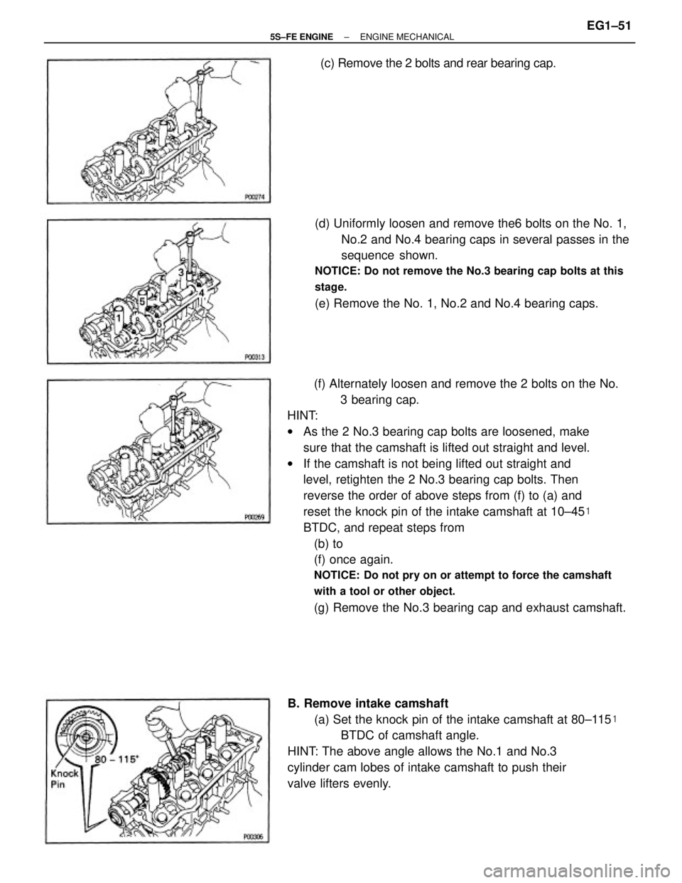
(f) Alternately loosen and remove the 2 bolts on the No.
3 bearing cap.
HINT:
wAs the 2 No.3 bearing cap bolts are loosened, make
sure that the camshaft is lifted out straight and level.
wIf the camshaft is not being lifted out straight and
level, retighten the 2 No.3 bearing cap bolts. Then
reverse the order of above steps from (f) to (a) and
reset the knock pin of the intake camshaft at 10±45�
BTDC, and repeat steps from
(b) to
(f) once again.
NOTICE: Do not pry on or attempt to force the camshaft
with a tool or other object.
(g) Remove the No.3 bearing cap and exhaust camshaft.(d) Uniformly loosen and remove the6 bolts on the No. 1,
No.2 and No.4 bearing caps in several passes in the
sequence shown.
NOTICE: Do not remove the No.3 bearing cap bolts at this
stage.
(e) Remove the No. 1, No.2 and No.4 bearing caps.
B. Remove intake camshaft
(a) Set the knock pin of the intake camshaft at 80±115�
BTDC of camshaft angle.
HINT: The above angle allows the No.1 and No.3
cylinder cam lobes of intake camshaft to push their
valve lifters evenly.(c) Remove the 2 bolts and rear bearing cap.
± 5S±FE ENGINEENGINE MECHANICALEG1±51
Page 102 of 4770

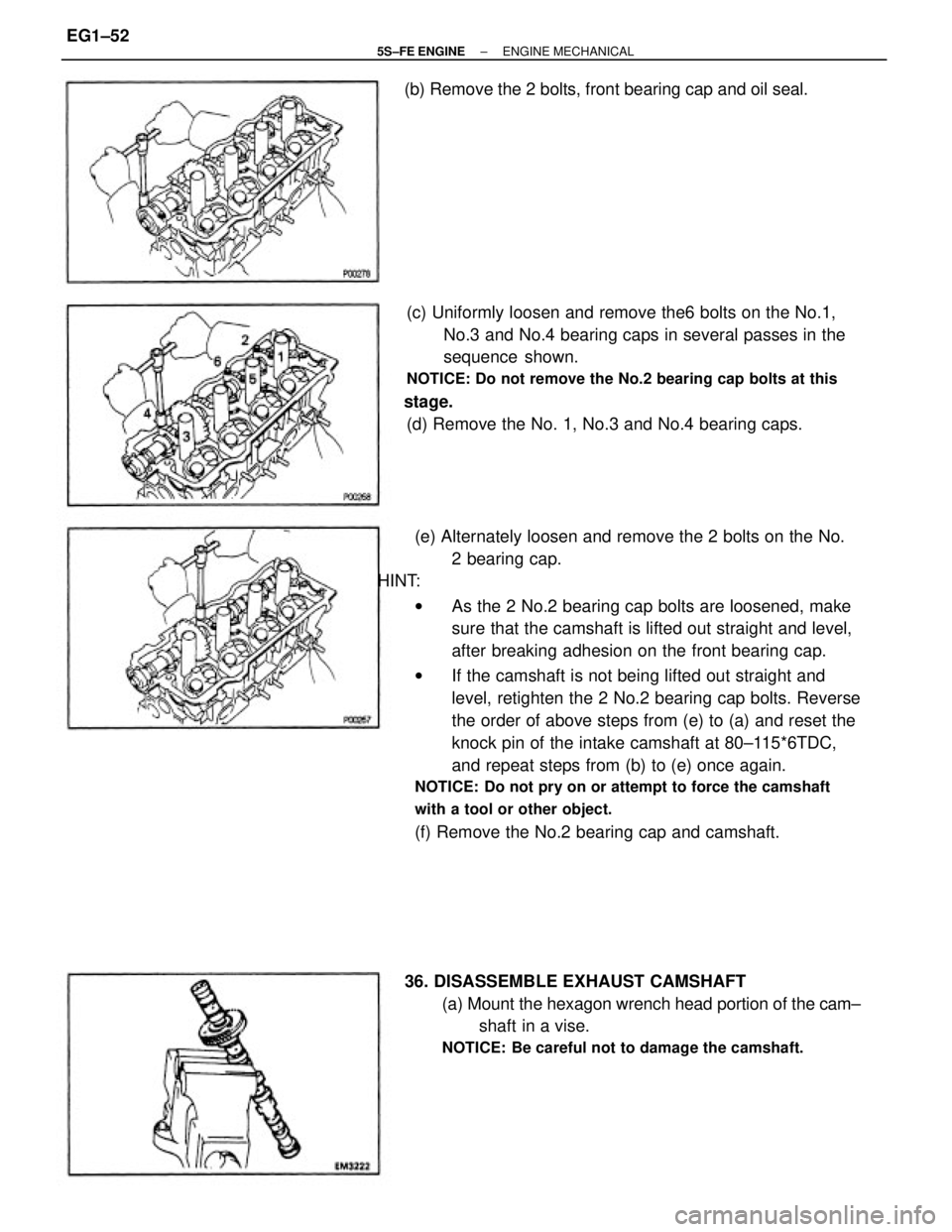
(e) Alternately loosen and remove the 2 bolts on the No.
2 bearing cap.
HINT:
wAs the 2 No.2 bearing cap bolts are loosened, make
sure that the camshaft is lifted out straight and level,
after breaking adhesion on the front bearing cap.
wIf the camshaft is not being lifted out straight and
level, retighten the 2 No.2 bearing cap bolts. Reverse
the order of above steps from (e) to (a) and reset the
knock pin of the intake camshaft at 80±115*6TDC,
and repeat steps from (b) to (e) once again.
NOTICE: Do not pry on or attempt to force the camshaft
with a tool or other object.
(f) Remove the No.2 bearing cap and camshaft. (c) Uniformly loosen and remove the6 bolts on the No.1,
No.3 and No.4 bearing caps in several passes in the
sequence shown.
NOTICE: Do not remove the No.2 bearing cap bolts at this
stage.
(d) Remove the No. 1, No.3 and No.4 bearing caps.
36. DISASSEMBLE EXHAUST CAMSHAFT
(a) Mount the hexagon wrench head portion of the cam±
shaft in a vise.
NOTICE: Be careful not to damage the camshaft.
(b) Remove the 2 bolts, front bearing cap and oil seal.
± 5S±FE ENGINEENGINE MECHANICALEG1±52
Page 113 of 4770
E. Inspect camshaft gear spring
Using a vernier caliper, measure the free distance
between the spring ends.
Free distance:
22.5 ± 22.9 mm (0.886 ± 0.902 in.)
If the free distance is not as specified, replace the gear
spring.
F. Inspect camshaft journal oil clearance
(a) Clean the bearing caps and camshaft journals.
(b) Place the camshafts on the cylinder head.
(c) Lay a strip of Plastigage across each of the camshaft
journals. D. Inspect camshaft bearings
Check that bearings for flaking and scoring.
If the bearings are damaged, replace the bearing caps
and cylinder head as a set.
(d) Install the bearing caps.
(See step 4 on pages EG1±69 to 71)
Torque: 19 N±m (190 kgf±cm, 14 ft±lbf)
NOTICE: Do not turn the camshaft.
(e) Remove the bearing caps.
± 5S±FE ENGINEENGINE MECHANICALEG1±63
Page 114 of 4770

G. Inspect camshaft thrust clearance
(a) Install the camshaft.
(See step 4 on pages EG1±69 to 71)
(b) Using a dial indicator, measure the thrust clearance
while moving the camshaft back and forth.
Standard thrust clearance:
Intake
0.045 ± 0.100 mm (0.0018 ± 0.0039 in.)
Exhaust
0.030 ± 0.085 mm (0.0012 ± 0.0033 in.)
Maximum thrust clearance:
Intake
0.12 mm (0.0047 in.)
Exhaust
0.10 mm (0.0039 in.)
If the thrust clearance is greater than maximum, re±
place the camshaft. If necessary, replace the bearing
caps and cylinder head as a set.
H. Inspect camshaft gear backlash
(a) Install the camshafts without installing the exhaust
cam sub gear.
(See step 4 on pages EG1±69 to 71)
(b) Using a dial indicator, measure the backlash.
Standard backlash:
0.020 ± 0.200 mm (0.0008 ± 0.0079 in.)
Maximum backlash:
6.30 mm (0.0188 in.)
If the backlash is greater then maximum, replace the
camshafts. (f) Measure the Plastigage at its widest point.
Standard oil clearance:
0.025 ± 0.062 mm (0.0010 ± 0.0024 In.)
Maximum oil clearance:
0.10 mm (0.0039 in.)
If the oil clearance is greater than maximum, replace
the camshaft. If necessary, replace the bearing caps
and cylinder head as a set.
(g) Completely remove the Plastigage.
± 5S±FE ENGINEENGINE MECHANICALEG1±64