Page 262 of 4770
(b) Using SST, connect terminals TE1 and E1 of the data
link connector 1.
SST 09843±18020
(c) Maintain engine speed in the range between 900 ±
1,300 rpm for 5 seconds. Check that it returns to idle
speed.
If the engine speed operation is not as specified,
check the IAC valve, wiring and ECM.
ON±VEHICLE INSPECTION
1. INSPECT IAC VALVE OPERATION
(a) Initial conditions:
wEngine at normal operating temperature
wIdle speed set correctly
wTransmission in neutral position
IDLE AIR CONTROL (IAC) VALVE
(d) Remove the SST.
SST 09843±18020
± 5S±FE ENGINEMFI/SFI SYSTEMEG1±212
Page 264 of 4770
IAC VALVE INSPECTION
INSPECT IAC VALVE OPERATION
(a) Connect the positive (+) lead from the battery to
terminal +B and negative (±) lead to terminal ISCC,
and check that the valve is closed.
IAC VALVE REMOVAL
(See Components for Removal and Installation)
1. REMOVE THROTTLE BODY
(See steps 1 to 6 on pages EG1±207 and 208)
IAC VALVE INSTALLATION
(See Components for Removal and Installation)
1. INSTALL IAC VALVE
(a) Place a new gasket on the throttle body. (b) Connect the positive (+) lead from the battery to
terminal +B and negative (±) lead to terminal ISCO,
and check that the valve is open. 2. REMOVE IAC VALVE
Remove the 4 screws, IAC valve and gasket.
± 5S±FE ENGINEMFI/SFI SYSTEMEG1±214
Page 377 of 4770

MATRIX CHART OF PROBLEM SYMPTOMS
When the malfunction code is not confirmed in the diagnostic trouble code check and the problem still can
not be confirmed in the basic inspection, then proceed to this step and perform troubleshooting according
to the numbered order given in the table below.
*: Except California specification vehicles.
Park/Neutral position switch circuitManifold absolute pressure sensor circuit
VSV circuit for fuel pressure control
Ignition signal circuit (Spark test)
After acceleration pedal depressed
After acceleration pedal released
Switch condition signal circuit
Muffler explosion (after fire)No initial combustion
Back up power source circuit
Hesitation/Poor accelerationNo complete combustion
ECM power source circuit
Starter and Starter relay
Engine control module
High engine idle speed
Low engine idle speedUnder normal condition
During A/C operationEngine does not crank
A/C cut control circuit Starter signal circuit
Soon after starting
Fuel system circuit
When N to D shiftIncorrect first idle
Poor
Driveability
IAC valve circuit Difficult to
start
Injector circuit
Rough idling
Does not
start
Compression
Suspect area
Cold engine
Ignition coil Engine Stall
EG R system
Hot engine
Poor Idling
Spark plug
A/T faultylG±10,30*
IG±11,30 Distributor
Symptom
ST±19,21
See page
IG±8,28* IG±6,26*
Hunting
Surging
EG1±400
EG1±410 EG1±390
EG1±403
EG1±408
EG1±415
EG1±419EG1±383EG1±372
EG1±428EG1±396
EG1 ±424
AX1±68 EG1±23
IN±36
± 5S±FE ENGINEMATRIX CHART OF PROBLEM SYMPTOMSEG1±327
Page 465 of 4770
CIRCUIT DESCRIPTION
The rotary solenoid type IAC valve is provided on the intake air chamber and intake air bypassing
the throttle valve is directed to the IAC valve through a passage.
In this way the intake air volume bypas±
sing the throttle valve is regulated, con±
trolling the engine speed.
The ECM operated only the IAC valve to
perform idle±up and provide feedback for
the target idling speed, a VSV for idle±up
control is also added (for air condition±
ing).
Check for open and short in harness and
connector between J/B No.2 and IAC valve,
IAC valve and ECM.
IAC Valve Circuit
Repair or replace harness or connector. Check voltage terminals ISCO, ISCC.
Check for ECM power source circuit.
DIAGNOSTIC CHART
Check operation of the IAC valve.Check and replace ECM.
Replace IAC valve.
± 5S±FE ENGINECIRCUIT INSPECTIONEG1±415
Page 468 of 4770
(1) Disconnect IAC valve connector.
(2) Remove IAC valve (See page EG1±213).
(1) Connect the positive (+) lead from the bat±
tery to terminal 2 (+ B) and negative (±) lead
to terminal 3 (ISCC), and check that the valve
is closed.
(2) Connect the. positive (+) lead from the bat±
tery to terminal 2 (+ B) and negative (±) lead
to terminal 1 (ISCO), and check that the valve
is open.
Check for open and short in harness and connector between J/B No.2
and IAC valve, IAC valve and engine control module (See page IN±31).
Check for ECM power source circuit (See page
EG1±403).
Check operation of the IAC valve.
Repair or replace harness or connector.Replace IAC valve. (1) The valve is closed.
(2) The valve is open.
± 5S±FE ENGINECIRCUIT INSPECTIONEG1±418
Page 4069 of 4770
IDLE AIR CONTROL (IAC) VALVE
SF±35
1468 Author�: Date�:
IDLE AIR CONTROL (IAC) VALVE
ON±VEHICLE INSPECTION
1. INSPECT IAC VALVE")
SF0DS±03
A07370
SST
E1
TE1
B01281
Ohmmeter
ISCC+B
ISCO
± SFI (5S±FE)IDLE AIR CONTROL (IAC) VALVE
SF±35
1468 Author�: Date�:
IDLE AIR CONTROL (IAC) VALVE
ON±VEHICLE INSPECTION
1. INSPECT IAC VALVE OPERATION
(a) Initial conditions:
�Engine at normal operating temperature
�Idle speed set correctly
�Transmission in neutral position
(b) Using SST, connect terminals TE1 and E1 of the DLC1.
SST 09843±18020
(c) After the engine speed is kept at 900 ± 1,300 rpm for 5 se-
conds, check that it returns to idle speed.
If the engine speed operation is not as specified, check the IAC
valve, wiring and ECM.
(d) Remove the SST from the DLC1.
SST 09843±18020
2. INSPECT IAC VALVE RESISTANCE
NOTICE:
ºColdº and ºHotº in these sentences express the tempera-
ture of the coils themselves. ºColdº is from ±10°C (14°F) to
50°C (122°F) and ºHotº is from 50°C (122°F) to 100°C
(212°F).
(a) Disconnect the IAC valve connector.
(b) Using an ohmmeter, measure the resistance between ter-
minal +B and other terminals (ISCC, ISCO).
Resistance:
Cold17.0 ± 24.5 W
Hot21.5 ± 28.5 W
If the resistance is not as specified, replace the IAC valve.
(c) Reconnect the IAC valve connector.
Page 4072 of 4770
SF0DV±03
S01477
Battery
ClosedISCC
+B
S01478
Battery
Open
ISCO +B SF±38
± SFI (5S±FE)IDLE AIR CONTROL (IAC) VALVE
1471 Author�: Date�:
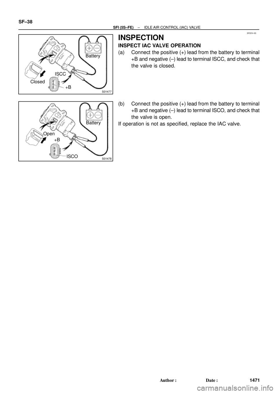
INSPECTION
INSPECT IAC VALVE OPERATION
(a) Connect the positive (+) lead from the battery to terminal
+B and negative (±) lead to terminal ISCC, and check that
the valve is closed.
(b) Connect the positive (+) lead from the battery to terminal
+B and negative (±) lead to terminal ISCO, and check that
the valve is open.
If operation is not as specified, replace the IAC valve.
Page 4142 of 4770
IDLE AIR CONTROL (IAC) VALVE
1541 Author�: Date�:
IDLE AIR CONTROL (IAC) VALVE
ON±VEHICLE INSPECTION
1. INSPECT")
SF07Y±03
S04529
E1DLC1
SST
TE1
DLC1
S04533
RSC
+B
RSO
Ohmmeter SF±42
± SFI (1MZ±FE)IDLE AIR CONTROL (IAC) VALVE
1541 Author�: Date�:
IDLE AIR CONTROL (IAC) VALVE
ON±VEHICLE INSPECTION
1. INSPECT IAC VALVE OPERATION
(a) Initial conditions:
�Engine at normal operating temperature
�Idle speed checked correctly
�Transmission in neutral position
�A/C switch OFF
(b) Using SST, connect terminals TE1 and E1 of the
DLC1.
SST 09843±18020
(c) After engine speed is kept at approx. 1,000 rpm for 5 se-
conds, check that it returns to idle speed.
If the engine speed operation is not as specified, check the IAC
valve, wiring and ECM.
(d) Remove the SST from the DLC1.
SST 09843±18020
2. INSPECT IAC VALVE RESISTANCE
NOTICE:
ºColdº and ºHotº in the following sentences express the
temperature of the coils themselves. ºColdº is from ±10°C
(14°F) to 50°C (122°F) and ºHotº is from 50°C (122°F) to
100°C (212°F).
(a) Disconnect the IAC valve connector.
(b) Using an ohmmeter, measure the resistance between ter-
minal +B and other terminals (RSC, RSO).
Resistance:
Cold17.0 ± 25.0 W
Hot21.5 ± 29.5 W
If resistance is not as specified, replace the IAC valve.
(c) Reconnect the IAC valve connector.
3. INSPECT AIR ASSIST SYSTEM
(a) Initial conditions:
�Engine at normal operating temperature
�Idle speed checked correctly
�Transmission in neutral position
�A/C switch OFF
 Using SST, connect terminals TE1 and E1 of the data
link connector 1.
SST 09843±18020
(c) Maintain engine speed in the range between 900 ±
1,300 rpm for 5 seconds. Check that it returns to idle")
 Connect the positive (+) lead from the battery to
terminal +B and negative (±) lead to terminal ISCC,
and check that the valve is closed.
IAC VALV")

 Disconnect IAC valve connector.
(2) Remove IAC valve (See page EG1±213).
(1) Connect the positive (+) lead from the bat±
tery to terminal 2 (+ B) and negative (±) lead
to terminal 3 (ISCC), and")