Page 822 of 4770
'99camry U
56
ÐBuilt±in child restraint
The built±in child restraint system mainly
consists of a child seat integrated in the
rear seat and 5±point seat belts. Refer to
the illustration to become familiar with the
parts of the system. This child restraint
system conforms to U.S. Motor Vehicle
Safety Standard No.213 and Canada Motor
Vehicle Safety Standard No.213.4.
1. Shoulder belts
2. Head restraint lock release button
3. Storage bag (for the head restraint and
upper pad)
4. Head restraint and upper pad
(for the rear seat)
5. Maximum shoulder height indicator
label
6. Removable pad
7. Seat belt buckle
8. Seat belt release strap (black)
9. Seat belt adjustment strap (gray tab)
10. Child seat cushion
11. Seat belt buckle release button
12. Seat belt tabs
13. Owner 's manual supplement
14. Shoulder belt clip
Page 2024 of 4770
BO0LW±01
H01824
H01825
± BODYSLIDING ROOF (TMMK Made)
BO±65
2413 Author�: Date�:
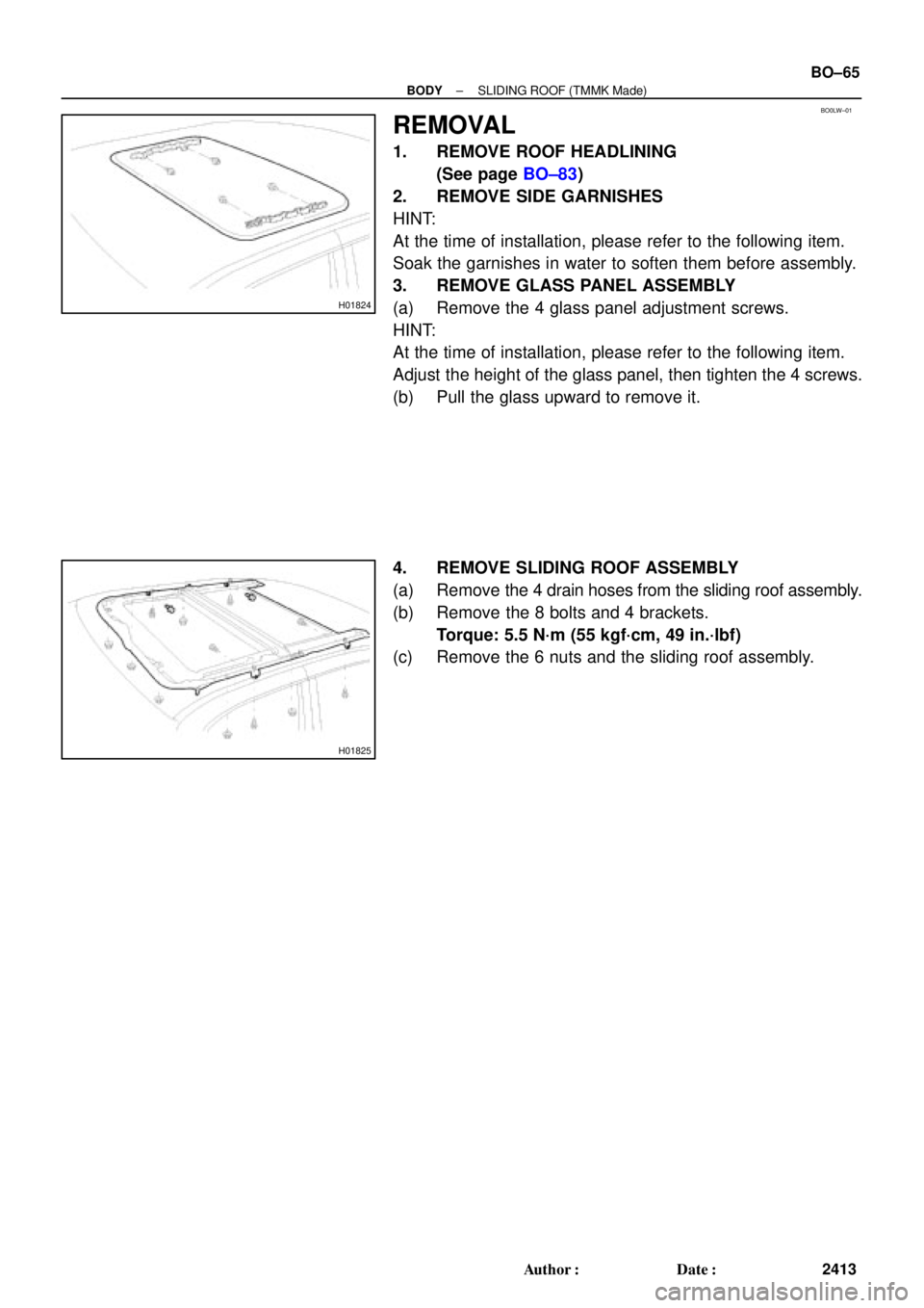
REMOVAL
1. REMOVE ROOF HEADLINING
(See page BO±83)
2. REMOVE SIDE GARNISHES
HINT:
At the time of installation, please refer to the following item.
Soak the garnishes in water to soften them before assembly.
3. REMOVE GLASS PANEL ASSEMBLY
(a) Remove the 4 glass panel adjustment screws.
HINT:
At the time of installation, please refer to the following item.
Adjust the height of the glass panel, then tighten the 4 screws.
(b) Pull the glass upward to remove it.
4. REMOVE SLIDING ROOF ASSEMBLY
(a) Remove the 4 drain hoses from the sliding roof assembly.
(b) Remove the 8 bolts and 4 brackets.
Torque: 5.5 N´m (55 kgf´cm, 49 in.´lbf)
(c) Remove the 6 nuts and the sliding roof assembly.
Page 2027 of 4770

Gear Pointer (Brown)
H01818
H01819
H01820
Parts shown
disassembled
for clarity BO±68
± BODYSLIDING ROOF (TMMK Made)
2416 Author�: Date�:
ADJUSTMENT
1. A")
BO0LY±01
H01817
Motor Housing
Pointer (Grey)
Gear Pointer (Brown)
H01818
H01819
H01820
Parts shown
disassembled
for clarity BO±68
± BODYSLIDING ROOF (TMMK Made)
2416 Author�: Date�:
ADJUSTMENT
1. ALIGN THE MOTOR TO ºOº POSITION
NOTICE:
The ºOº position is the same as the sliding roof ºflush º
position (sliding roof closed).
Use the vehicle sliding roof switch or a hex wrench to align the
gear pointer with the motor housing pointer as shown.
NOTICE:
Use only the sliding roof switch to electrically operate the
motor or sliding roof. Do not use any other electrical
source to power the motor. If the sliding roof switch (under
vehicle power) is not available, use a hex wrench to align
the motor pointers.
2. REMOVE DRIVE GEAR ASSEMBLY
3. REMOVE GLASS PANEL
(a) Remove the 4 glass panels adjustment screws.
HINT:
At the time of installation, please refer to the following item.
Adjust the height of the glass panel, then tighten the 4 screws.
(b) Pull the glass upward to remove it.
4. ALIGN SLIDING ROOF COMPONENTS
(a) Verify the hook appears as shown.
(b) Align the cable arm hole with the lift arm hole.
HINT:
Using a screwdriver, move the LH and RH cable assemblies for-
ward and backward to align the holes in the cable arm and lifter
arm.
(c) Temporarily insert a 3 mm (0.12 in.) pin through the align-
ment holes in the cable arm and lifter arm.
HINT:
Verify the cam block alignment hole is aligned with the lift arm
alignment hole. Misalignment at this point will result in a mal-
function of the sliding roof mechanism.
5. REINSTALL DRIVE GEAR ASSEMBLY
HINT:
Before reinstalling the drive gear assembly, double check the
alignment of the gear pointers.