Page 23 of 4770

3
CAMRY ± NEW FEATURES
172CM14
Fuel
Pressure
SensorFuel Temp.
SensorFuel
Pressure
RegulatorFuel Shutoff ValveFuel Tank
Fuel Shutoff ValveRelief Valve
Inlet Check
Valve
Fuel Temp.
Sensor
Coupler
Tank Valve Assembly
Vent Tube Manual
Shutoff
Valve Oil
Separator
Fuel Shutoff Valve Injectors
Delivery Pipe Discharge
ValveFuel
Pressure
SensorFuel
Filter43
6. Fuel System
General
�The compressed gas [maximum pressure approximately 250 kg / cm
2 (3600 psi, 24.8 MPa) @ 21�C
(70�F)] from the CNG fuel tank located in the rear section of the vehicle is routed via a fuel filter to the
engine compartment. The pressure of the fuel is then reduced to 8 kg / cm
2 (114 psi, 785 kPa).
�A pressure regulator and injectors designed exclusively for CNG application have been adopted.
�A fuel pressure sensor and a fuel temperature sensor that are used for the correction of the fuel injection
volume are located on the delivery pipe.
�The fuel tank, pressure regulator, and the delivery pipe are provided with shutoff valves that shut off the
fuel when the ignition switch is turned OFF.
In addition, these valves shut off the fuel when the engine stalls, the SRS airbag is deployed, or the pres-
sure in the main pipe becomes abnormally low.
�A fuel temperature sensor for the fuel gauge is mounted on the tank valve assembly, and a fuel pressure
sensor is mounted immediately upstream of the pressure regulator.
� Fuel System Diagram �
Page 32 of 4770
CAMRY ± NEW FEATURES
167CN11
Intake Air
Temp. SensorSpeedometerFuel Gage & Warning
MIL
DLC3
Airbag Sensor Assembly
ECM
VSV
(for EGR)
EGR Vacuum
ModulatorIAC Valve
Throttle
Position
Sensor
Fuel Temp.
Sensor
Fuel Shutoff
ValveFuel
Pressure
Regulator
Oil
SeparatorFuel
Shutoff
Valve
Fuel
Pressure
Sensor
EGR Valve
Crankshaft Position
Sensor Manifold
Absolute
Pressure
SensorFuel Pressure
Sensor
Engine Coolant
Temp. Sensor
Camshaft
Position
Sensor
Air Fuel
Ratio Sensor
WU-TWC
Heated Oxygen Sensor
TWCManual Fuel
Shutoff
ValveFuel Filter
Fuel TankFuel Temp. Sensor
Fuel Shutoff Valve
Coupler 52
Engine Control System Diagram
Page 60 of 4770

3. Delco Battery:
CHECK HYDROMETER
Green Dot visible:
Battery is adequately charged
Dark (Green Dot not visible):
Battery must be charged
Clear or Light Yellow:
Replace battery
HINT: There is no need to add water during the entire
service life of the battery.
AIR FILTER INSPECTION
1. INSPECT AIR FILTER
Visually check that the element is not excessively
dirty, damaged or oily.
2. CLEAN AIR FILTER
Clean the element with compressed air.
First blow air from the inside thoroughly. Then blow
off the outside of the element.B. Except Maintenance Free Battery
Check the specific gravity of each cell.
Standard specific gravity:
55D23L battery for GNB Incorporated
1.25 ± 1.27 at 205C (685F)
55D23L battery for JOHNSON CONTROLS
1.26 ± 1.28 at 275C (815F)
80D26L battery for GNB Incorporated
1.27 ± 1.29 at 205C (685F)
80D26L battery for JOHNSON CONTROLS
1.28 ± 1.30 at 27�C (81�F)
If the gravity is less than specification, charge the
battery.
HINT: Check the indicator as shown in the illustration.
HIGH±TENSION CORDS INSPECTION
1. DISCONNECT HIGH±TENSION CORDS FROM
SPARK PLUGS
Disconnect the high ± tension cords at the rubber
boot. Do not pull on the high±tension cords.
NOTICE: Pulling on or bending the cords may damage the
conductor inside.
± 5S±FE ENGINEENGINE MECHANICALEG1±10
Page 72 of 4770

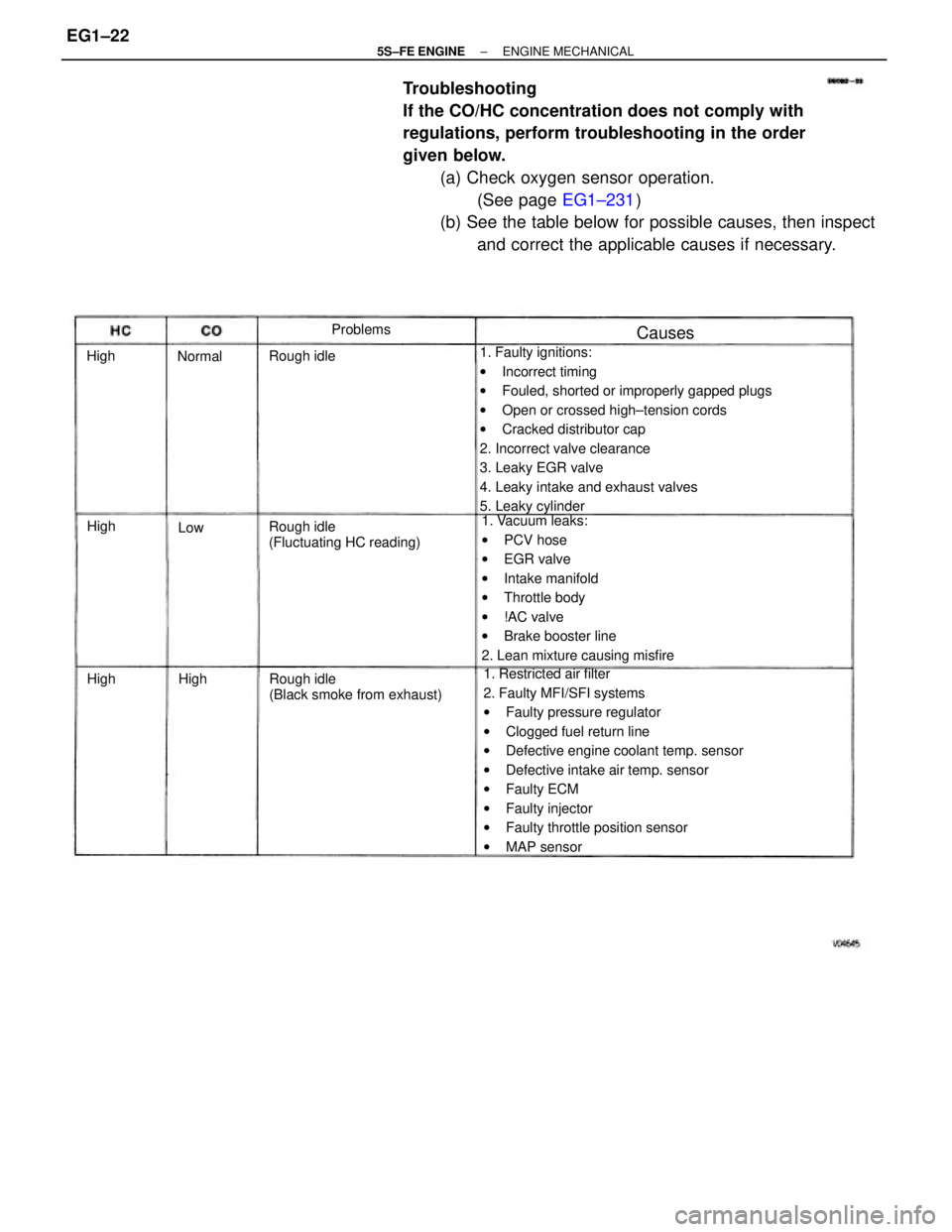
Troubleshooting
If the CO/HC concentration does not comply with
regulations, perform troubleshooting in the order
given below.
(a) Check oxygen sensor operation.
(See page EG1±231)
(b) See the table below for possible causes, then inspect
and correct the applicable causes if necessary.
1. Faulty ignitions:
wIncorrect timing
wFouled, shorted or improperly gapped plugs
wOpen or crossed high±tension cords
wCracked distributor cap
2. Incorrect valve clearance
3. Leaky EGR valve
4. Leaky intake and exhaust valves
5. Leaky cylinder
1. Restricted air filter
2. Faulty MFI/SFI systems
wFaulty pressure regulator
wClogged fuel return line
wDefective engine coolant temp. sensor
wDefective intake air temp. sensor
wFaulty ECM
wFaulty injector
wFaulty throttle position sensor
wMAP sensor 1. Vacuum leaks:
wPCV hose
wEGR valve
wIntake manifold
wThrottle body
w!AC valve
wBrake booster line
2. Lean mixture causing misfire
Rough idle
(Black smoke from exhaust) Rough idle
(Fluctuating HC reading) Rough idleProblems
Causes
Normal
High High High
HighLow
± 5S±FE ENGINEENGINE MECHANICALEG1±22
Page 194 of 4770

No. 1 balance shaft housing x No. 2 balance shaft housing (1st)
No. 1 balance shaft housing x No. 2 balance shaft housing (2nd)
FR engine mounting insulator x Front suspension member
RR engine mounting insulator x Front suspension member Exhaust manifold stay x FR engine mounting insulator No. 1 air intake chamber stay x Intake manifold
RR engine mounting insulator x Cylinder block
FR engine mounting insulator x Cylinder block No. 1 air intake chamber stay x Cylinder head
No. 1 exhaust manifold stay x Cylinder block
Connecting rod cap x Connecting rod (2nd) Connecting rod cap x Connecting rod (1 st)
LH engine mounting insulator x Transaxle No. 1 exhaust manifold stay x WU ±TWC Water bypass pipe x Water pump cover
Fuel inlet hose x Fuel filter (Union bolt) No. 3 timing belt cover x Cylinder head
Intake manifold stay x Intake manifoldCamshaft bearing cap x Cylinder head
Intake manifold stay x Cylinder blockCylinder head x Cylinder block (2nd)
Rear oil seal retainer x Cylinder block Exhaust manifold stay x WU ±TWC
PS pump bracket x Cylinder block Main bearing cap x Cylinder block Generator bracket x Cylinder head
A/C compressor x Cylinder block Pulsation damper x Delivery pipe
Exhaust manifold x Cylinder head
Engine balancer x Cylinder block
Front exhaust pipe x WU ±TWC Spark plug tube x Cylinder head
Rear end plate x Cylinder block Throttle body x Intake manifold Intake manifold x Cylinder heedEngine hanger x Cylinder head
Drive plate x Crankshaft (A/T)Knock sensor x Cylinder block Delivery pipe x Cylinder head
PS pump x PS pump bracketWU±TWC x Exhaust manifold
Flywheel x Crankshaft (M/T) Water outlet x Cylinder headEGR valve x intake manifold
EGR pipe x Cylinder head
± 5S±FE ENGINEENGINE MECHANICALEG1±144
Page 200 of 4770

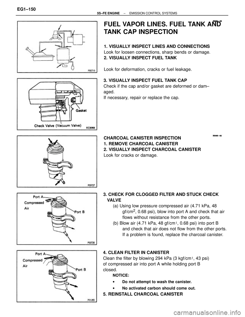
3. CHECK FOR CLOGGED FILTER AND STUCK CHECK
VALVE
(a) Using low pressure compressed air (4.71 kPa, 48
gf/cm
2, 0.68 psi), blow into port A and check that air
flows without resistance from the other ports.
(b) Blow air (4.71 kPa, 48 gf/cm�, 0.68 psi) into port B
and check that air does not flow from the other ports.
If a problem is found, replace the charcoal canister.
4. CLEAN FILTER IN CANISTER
Clean the filter by blowing 294 kPa (3 kgf/cm�, 43 psi)
of compressed air into port A while holding port B
closed.
NOTICE:
wDo not attempt to wash the canister.
wNo activated carbon should come out.
5. REINSTALL CHARCOAL CANISTER
FUEL VAPOR LINES. FUEL TANK AND
TANK CAP INSPECTION
1. VISUALLY INSPECT LINES AND CONNECTIONS
Look for loosen connections, sharp bends or damage.
2. VISUALLY INSPECT FUEL TANK
Look for deformation, cracks or fuel leakage.
CHARCOAL CANISTER INSPECTION
1. REMOVE CHARCOAL CANISTER
2. VISUALLY INSPECT CHARCOAL CANISTER
Look for cracks or damage. 3. VISUALLY INSPECT FUEL TANK CAP
Check if the cap and/or gasket are deformed or dam±
aged.
If necessary, repair or replace the cap.
± 5S±FE ENGINEEMISSION CONTROL SYSTEMSEG1±150
Page 203 of 4770
EGR SYSTEM INSPECTION
1. CHECK AND CLEAN FILTER IN EGR VACUUM
MODULATOR
(a) Check the filter for contamination or damage.
(b) Using compressed air, clean the filter.
HINT: Install the filter with the coarser surface facing
the atmospheric side (outward).
2. PREPARATION
Using a 3±way connector, connect a vacuum gauge
to the hose between the EGR valve and VSV.
3. CHECK SEATING OF EGR VALVE
Start the engine and check that the engine starts and
runs at idle.
6. CHECK VSV AND EGR VACUUM MODULATOR
WITH HOT ENGINE
(a) Warm up the engine.
(b) Check that the vacuum gauge indicates low vacuum
at 2,500 rpm. 5. CHECK VSV
(a) The engine coolant temperature should be below
60�C (140�F) (A/T) or 55�C (131 �F) (M/T).
(b) Check that the vacuum gauge indicates zero at 2.500
rpm. 4. CONNECT TERMINALS TE1 AND E1
Using SST, connect terminals TE 1 and E 1 of the data
link connector 1.
SST 09843±18020
± 5S±FE ENGINEEMISSION CONTROL SYSTEMSEG1±153
Page 205 of 4770
VSV INSPECTION (Except California)
1. REMOVE VSV
(a) Disconnect the following connector and hoses:
(1) VSV connector
(2) Vacuum hose (from EGR valve) from port E of
VSV
(3) Vacuum hose (from port ªQº of EGR vacuum
modulator) from port G of VSV 2. INSPECT VSV
A. Inspect VSV for open circuit
Using an ohmmeter, check that there is continuity
between the terminals.
Resistance (Cold):
33±39�
If there is no continuity, replace the VSV.
B. Inspect VSV for ground
Using an ohmmeter, check that there is no continuity
between each terminal and the body.
If there is continuity, replace the VSV.
(b) Apply battery voltage across the terminals.
(c) Check that air flows from port E to the filter.
If operation is not as specified, replace the VSV.
3. REINSTALL VSVC. Inspect VSV operation
(a) Check that air flows from port E to port G.
± 5S±FE ENGINEEMISSION CONTROL SYSTEMSEG1±155