Page 4160 of 4770

SF08F±04
S04525
Continuity Ohmmeter
S04524
No Continuity Ohmmeter
FI6393
Air
E
Filter
S04523
Air
E
F
Battery SF±60
± SFI (1MZ±FE)VSV FOR ACOUSTIC CONTROL INDUCTION
SYSTEM (ACIS)
1559 Author�: Date�:
INSPECTION
1. REMOVE V±BANK COVER, HIGH±TENSION CORD
COVER AND EMISSION CONTROL VALVE SET
2. REMOVE VSV
(a) Disconnect the 2 vacuum hoses from the VSV.
(b) Remove the screw and VSV.
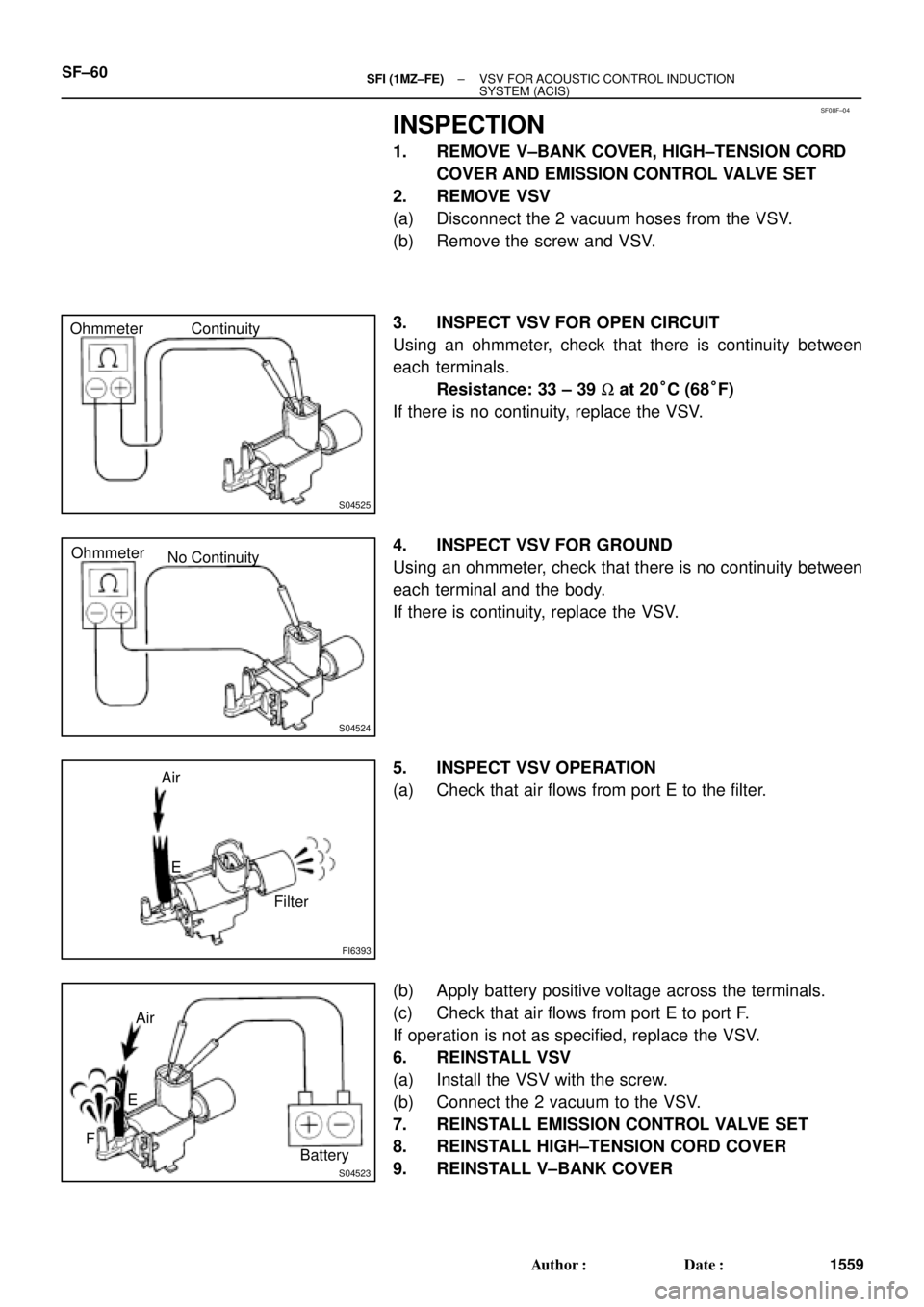
3. INSPECT VSV FOR OPEN CIRCUIT
Using an ohmmeter, check that there is continuity between
each terminals.
Resistance: 33 ± 39 W at 20°C (68°F)
If there is no continuity, replace the VSV.
4. INSPECT VSV FOR GROUND
Using an ohmmeter, check that there is no continuity between
each terminal and the body.
If there is continuity, replace the VSV.
5. INSPECT VSV OPERATION
(a) Check that air flows from port E to the filter.
(b) Apply battery positive voltage across the terminals.
(c) Check that air flows from port E to port F.
If operation is not as specified, replace the VSV.
6. REINSTALL VSV
(a) Install the VSV with the screw.
(b) Connect the 2 vacuum to the VSV.
7. REINSTALL EMISSION CONTROL VALVE SET
8. REINSTALL HIGH±TENSION CORD COVER
9. REINSTALL V±BANK COVER
Page 4561 of 4770

EVAP SYSTEM OPERATION INFORMATION ± EG005-01 April 27, 2001
Page 2 of 14
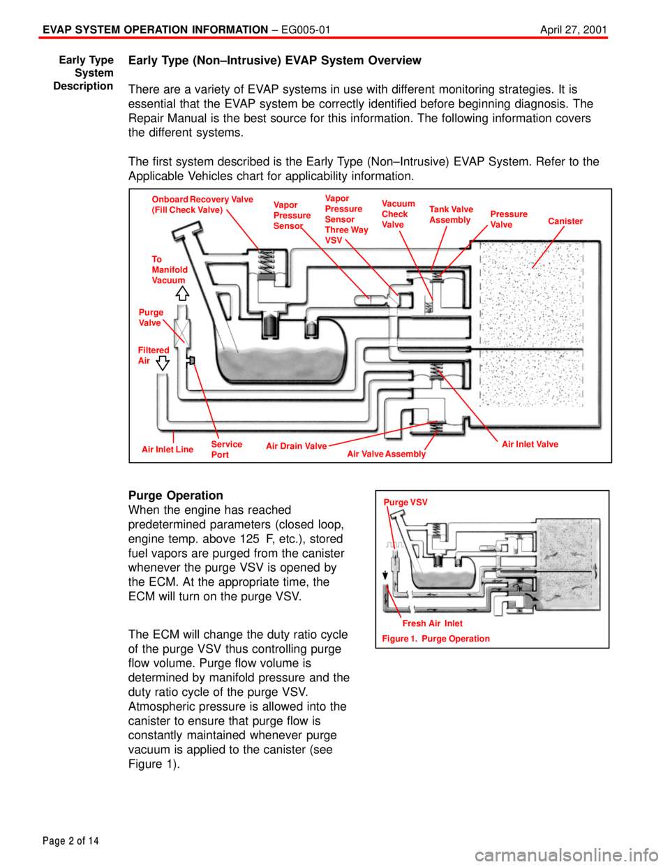
Early Type (Non±Intrusive) EVAP System Overview
There are a variety of EVAP systems in use with different monitoring strategies. It is
essential that the EVAP system be correctly identified before beginning diagnosis. The
Repair Manual is the best source for this information. The following information covers
the different systems.
The first system described is the Early Type (Non±Intrusive) EVAP System. Refer to the
Applicable Vehicles chart for applicability information.
Onboard Recovery Valve
(Fill Check Valve)Vapor
Pressure
SensorVapor
Pressure
Sensor
Three Way
VSVVacuum
Check
ValveTank Valve
AssemblyPressure
ValveCanister
To
Manifold
Vacuum
Purge
Valve
Filtered
Air
Air Drain Valve
Air Valve AssemblyAir Inlet ValveAir Inlet LineService
Port
Purge Operation
When the engine has reached
predetermined parameters (closed loop,
engine temp. above 125�F, etc.), stored
fuel vapors are purged from the canister
whenever the purge VSV is opened by
the ECM. At the appropriate time, the
ECM will turn on the purge VSV.
The ECM will change the duty ratio cycle
of the purge VSV thus controlling purge
flow volume. Purge flow volume is
determined by manifold pressure and the
duty ratio cycle of the purge VSV.
Atmospheric pressure is allowed into the
canister to ensure that purge flow is
constantly maintained whenever purge
vacuum is applied to the canister (see
Figure 1).
Early Type
System
Description
Figure 1. Purge OperationFresh Air Inlet
Purge VSV
Page 4564 of 4770
EVAP SYSTEM OPERATION INFORMATION ± EG005-01 April 27, 2001
Page 5 of 14
Late Type (Intrusive EVAP System) (Except ECHO)
Onboard Recovery Valve
(Fill Check Valve)Vapor
Pressure
SensorVacuum
Check
ValveTank Valve
AssemblyTank
Pressure
Valve
Canister
To
Manifold
Vacuum
Purge
VSV
Filtered
Air
Air Drain Valve
Air Valve AssemblyAir Inlet ValveCanister
Closed Valve
Bypass
VSVAir
Inlet LineService
Port
Tank Side
The bypass VSV and the fill check valve
assembly isolates the tank pressure side
from the canister side (see Figure 1).
Canister Side
The bypass VSV and the Fill Check valve
also isolate the canister side from the
tank side (see Figure 2).
Late Type
System
Description
(Continued)
Except ECHO
Figure 1. Fuel Tank Side of System
Except ECHO
Figure 2. Canister Side of System
Page 4565 of 4770

EVAP SYSTEM OPERATION INFORMATION ± EG005-01 April 27, 2001
Page 6 of 14
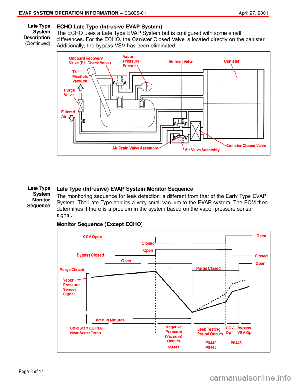
ECHO Late Type (Intrusive EVAP System)
The ECHO uses a Late Type EVAP System but is configured with some small
differences. For the ECHO, the Canister Closed Valve is located directly on the canister.
Additionally, the bypass VSV has been eliminated.
Onboard Recovery
Valve (Fill Check Valve)Vapor
Pressure
Sensor
Air Inlet ValveCanister
Canister Closed ValveAir Valve AssemblyAir Drain Valve Assembly
To
Manifold
Vacuum
Purge
Valve
Filtered
Air
Late Type (Intrusive) EVAP System Monitor Sequence
The monitoring sequence for leak detection is different from that of the Early Type EVAP
System. The Late Type applies a very small vacuum to the EVAP system. The ECM then
determines if there is a problem in the system based on the vapor pressure sensor
signal.
Monitor Sequence (Except ECHO)
CCV Open
Purge ClosedOpenClosed
Purge ClosedOpenOpen
Cold Start ECT/IAT
Near Same TempNegative
Pressure
(Vacuum)
OccursLeak Testing
Period OccursCCV
Op Open
Time in Minutes Bypass Closed
Closed
Bypass
VSV Op Vapor
Pressure
Sensor
Signal
P0441P0440
P0442P0446
Late Type
System
Description
(Continued)
Late Type
System
Monitor
Sequence
Page 4569 of 4770

EVAP SYSTEM OPERATION INFORMATION ± EG005-01 April 27, 2001
Page 10 of 14
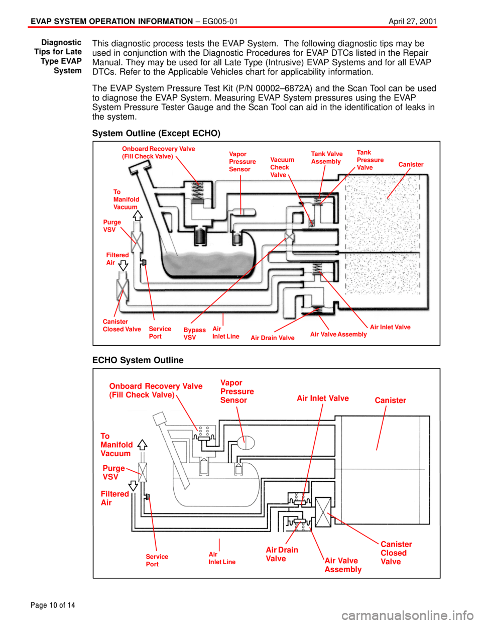
This diagnostic process tests the EVAP System. The following diagnostic tips may be
used in conjunction with the Diagnostic Procedures for EVAP DTCs listed in the Repair
Manual. They may be used for all Late Type (Intrusive) EVAP Systems and for all EVAP
DTCs. Refer to the Applicable Vehicles chart for applicability information.
The EVAP System Pressure Test Kit (P/N 00002±6872A) and the Scan Tool can be used
to diagnose the EVAP System. Measuring EVAP System pressures using the EVAP
System Pressure Tester Gauge and the Scan Tool can aid in the identification of leaks in
the system.
System Outline (Except ECHO)
Onboard Recovery Valve
(Fill Check Valve)Vapor
Pressure
SensorVacuum
Check
ValveTank Valve
AssemblyTank
Pressure
Valve
Canister
To
Manifold
Vacuum
Purge
VSV
Filtered
Air
Air Drain Valve
Air Valve AssemblyAir Inlet ValveCanister
Closed Valve
Bypass
VSVAir
Inlet LineService
Port
ECHO System Outline
Onboard Recovery Valve
(Fill Check Valve)
To
Manifold
Vacuum
Filtered
AirPurge
VSV
Air Drain
Valve
Air Valve
Assembly
Canister
Closed
Valve
Canister
Vapor
Pressure
Sensor
Air Inlet Valve
Air
Inlet LineService
Port
Diagnostic
Tips for Late
Type EVAP
System