Page 3677 of 4770
 Care must be taken when jacking up and supporting the
vehicle. Be sure to lift and support the")
IN0253
WRONG CORRECT
IN0252
WRONG CORRECT IN±6
± INTRODUCTIONREPAIR INSTRUCTIONS
6 Author�: Date�:
(k) Care must be taken when jacking up and supporting the
vehicle. Be sure to lift and support the vehicle at the prop-
er locations (See page IN±8).
�Cancel the parking brake on the level place and
shift the transmission in Neutral (or N position).
�When jacking up the front wheels of the vehicle at
first place stoppers behind the rear wheels.
�When jacking up the rear wheels of the vehicle at
first place stoppers before the front wheels.
�When either the front or rear wheels only should be
jacked up, set rigid racks and place stoppers in front
and behind the other wheels on the ground.
�After the vehicle is jacked up, be sure to support it
on rigid racks . It is extremely dangerous to do any
work on a vehicle raised on a jack alone, even for
a small job that can be finished quickly.
(l) Observe the following precautions to avoid damage to the
following parts:
(1) Do not open the cover or case of the ECU unless
absolutely necessary. (If the IC terminals are
touched, the IC may be destroyed by static electric-
ity.)
(2) To disconnect vacuum hoses, pull off the end, not
the middle of the hose.
(3) To pull apart electrical connectors, pull on the con-
nector itself, not the wires.
(4) Be careful not to drop electrical components, such
as sensors or relays. If they are dropped on a hard
floor, they should be replaced and not reused.
(5) When steam cleaning an engine, protect the elec-
tronic components, air filter and emission±related
components from water.
(6) Never use an impact wrench to remove or install
temperature switches or temperature sensors.
(7) When checking continuity at the wire connector, in-
sert the tester probe carefully to prevent terminals
from bending.
(8) When using a vacuum gauge, never force the hose
onto a connector that is too large. Use a step±down
adapter for adjustment. Once the hose has been
stretched, it may leak air.
Page 3713 of 4770

IACIdle Air ControlIdle Speed Control (ISC)
IATIntake Air TemperatureIntake or Inlet Air Temperature")
IN±42
± INTRODUCTIONTERMS
42 Author�: Date�:
HO2SHeated Oxygen SensorHeated Oxygen Sensor (HO2S)
IACIdle Air ControlIdle Speed Control (ISC)
IATIntake Air TemperatureIntake or Inlet Air Temperature
ICMIgnition Control Module±
IFIIndirect Fuel InjectionIndirect Injection (IDL)
IFSInertia Fuel±Shutoff±
ISCIdle Speed Control±
KSKnock SensorKnock Sensor
MAFMass Air FlowAir Flow Meter
MAPManifold Absolute PressureManifold Pressure
Intake Vacuum
MCMixture Control
Electric Bleed Air Control Valve (EBCV)
Mixture Control Valve (MCV)
Electric Air Control Valve (EACV)
MDPManifold Differential Pressure±
MFIMultiport Fuel InjectionElectronic Fuel Injection (EFI)
MILMalfunction Indicator LampCheck Engine Lamp
MSTManifold Surface Temperature±
MVZManifold Vacuum Zone±
NVRAMNon±Volatile Random Access Memory±
O2SOxygen SensorOxygen Sensor, O2 Sensor (O2S)
OBDOn±Board DiagnosticOn±Board Diagnostic System (OBD)
OCOxidation Catalytic ConverterOxidation Catalyst Convert (OC), CCo
OPOpen LoopOpen Loop
PAIRPulsed Secondary Air InjectionAir Suction (AS)
PCMPowertrain Control Module±
PNPPark/Neutral Position±
PROMProgrammable Read Only Memory±
PSPPower Steering Pressure±
PTOXPeriodic Trap OxidizerDiesel Particulate Filter (DPF)
Diesel Particulate Trap (DPT)
RAMRandom Access MemoryRandom Access Memory (RAM)
RMRelay Module±
ROMRead Only MemoryRead Only Memory (ROM)
RPMEngine SpeedEngine Speed
SCSuperchargerSupercharger
SCBSupercharger BypassE±ABV
SFISequential Multiport Fuel InjectionElectronic Fuel Injection (EFI), Sequential Injection
SPLSmoke Puff Limiter±
SRIService Reminder Indicator±
SRTSystem Readiness Test±
STScan Tool±
TBThrottle BodyThrottle Body
TBIThrottle Body Fuel InjectionSingle Point Injection
Central Fuel Injection (Ci)
TCTurbochargerTurbocharger
TCCTorque Converter ClutchTorque Converter
Page 3755 of 4770

1MZ±FE: (See page EM±15)
2. INSPECT DRIVE BELTS
5S±F")
MA00L±01
P00495
Outside
Inside
± MAINTENANCEENGINE
MA±5
48 Author�: Date�:
ENGINE
INSPECTION
1. REPLACE TIMING BELT
5S±FE: (See page EM±17)
1MZ±FE: (See page EM±15)
2. INSPECT DRIVE BELTS
5S±FE: (See page CH±1)
1MZ±FE: (See page CH±1)
3. REPLACE SPARK PLUGS
5S±FE: (See page IG±1)
1MZ±FE: (See page IG±1)
4. INSPECT AIR FILTER
(a) Visually check that the air filter is not excessively dirty or
oily.
(b) Clean the air filter with compressed air.
First blow from the inside thoroughly, then blow off the outside
of the air filter.
5. REPLACE AIR FILTER
Replace the air filter with a new one.
6. REPLACE ENGINE OIL AND OIL FILTER
5S±FE: (See page LU±2)
1MZ±FE: (See page LU±3)
7. REPLACE ENGINE COOLANT
5S±FE: (See page CO±2)
1MZ±FE: (See page CO±2)
8. 1MZ±FE:
INSPECT CHARCOAL CANISTER
(See page EC±6)
9. REPLACE GASKET IN FUEL TANK CAP
5S±FE: (See page EC±6)
1MZ±FE: (See page EC±6)
10. INSPECT FUEL LINES AND CONNECTIONS
5S±FE: (See page EC±6)
1MZ±FE: (See page EC±6)
11. INSPECT EXHAUST PIPES AND MOUNTINGS
5S±FE: (See page EC±15)
1MZ±FE: (See page EC±17)
12. ADJUST VALVE CLEARANCE
5S±FE: (See page EM±4)
1MZ±FE: (See page EM±4)
Page 3976 of 4770

177 Author�: Date�:
TORQUE SPECIFICATION
Part tightenedN´mkgf´cmft´lbf
Timing belt plate x Oil pump88069 in.´lbf
No.1 idler pu")
SS077±03
SS±14
± SERVICE SPECIFICATIONSENGINE MECHANICAL (1MZ±FE)
177 Author�: Date�:
TORQUE SPECIFICATION
Part tightenedN´mkgf´cmft´lbf
Timing belt plate x Oil pump88069 in.´lbf
No.1 idler pulley x Oil pump3435025
No.2 idler pulley x No.2 idler pulley bracket4344032
Camshaft timing pulley x Camshaft
for SST125
881,300
90094
65
Timing belt tensioner x Oil pump2728020
RH engine mounting bracket x Cylinder block2829021
No.2 timing belt cover x No.3 timing belt cover8.58574 in.´lbf
No.1 timing belt cover x Oil pump8.58574 in.´lbf
Crankshaft pulley x Crankshaft2152,200159
No.2 generator bracket x Engine RH mounting bracket2829021
Cylinder head x Cylinder block 12 pointed head bolt 1st
2nd
Recessed head bolt54
Turn 90°
18.5550
Turn 90°
18540
Turn 90°
13
Camshaft bearing cap x Cylinder head1616012
Cylinder head cover x Cylinder head88069 in.´lbf
Exhaust manifold x Cylinder head4950036
Exhaust manifold stay x Exhaust manifold
Except California A/T and all M/T
California A/T and all M/T
20
34200
35015
25
Exhaust manifold stay x Transmission housing
Except California A/T
California A/T
20
34200
35015
25
No.1 EGR pipe x RH exhaust manifold121209
No.1 EGR pipe x EGR cooler121209
PS pump bracket x RH cylinder head4344032
Oil dipstick guide x LH cylinder head88069 in.´lbf
Water inlet pipe x LH cylinder head19.520014
Cylinder head rear plate x LH cylinder head88069 in.´lbf
No.3 timing belt cover x Cylinder head8.58574 in.´lbf
Water outlet x Intake manifold1515011
Fuel inlet hose x Fuel filter2930021
Intake manifold x Cylinder head1515011
Air intake chamber x Intake manifold4344032
No.2 EGR pipe x Air intake chamber121209
No.2 EGR pipe x EGR cooler121209
No.1 engine hanger x Air intake chamber3940029
No.1 engine hanger x RH cylinder head3940029
Air intake chamber stay x Air intake chamber19.520014
Air intake chamber stay x RH cylinder head19.520014
Rear engine mounting insulator x Cylinder block6465047
Front engine mounting insulator x Cylinder block6465047
Engine moving control rod x RH engine mounting bracket6465047
Engine moving control rod x RH fender apron6465047
No.2 RH engine mounting stay x No.2 RH engine mounting bracket6465047
Page 3984 of 4770
SS10A±01
SS±22
± SERVICE SPECIFICATIONSSFI (1MZ±FE)
185 Author�: Date�:
TORQUE SPECIFICATION
Part tightenedN´mkgf´cmft´lbf
Fuel line (Union bolt type)2930021
Fuel line (Flare nut type) using SST2828521
Fuel pump assembly x Fuel tank44035 in.´lbf
Fuel filter x Fuel pump bracket22017 in.´lbf
Fuel pressure regulator x Fuel pump bracket22017 in.´lbf
Delivery pipe x Intake manifold101007
No.1 fuel pipe x Intake manifold19.520014
Fuel tank band x Body3940029
Throttle body x Air intake chamber19.520014
Intake air control valve x Air intake chamber14.514510
ECT sensor x Water outlet2020014
Knock sensor x Cylinder block3940029
A/F sensor x Exhaust manifold4445032
Heated oxygen sensor (Bank 1, 2 sensor 1) x Exhaust manifold4445032
Heated oxygen sensor (Bank 1 sensor 2) x Exhaust pipe4445032
Page 4077 of 4770
SF0E0±03
S05259
Ohmmeter
Continuity
S05260
Ohmmeter
No Continuity
S05261
Air
E
G
S05262
BatteryAir
E
Filter
± SFI (5S±FE)VSV FOR EXHAUST GAS RECIRCULATION (EGR)
SF±43
1476 Author�: Date�:
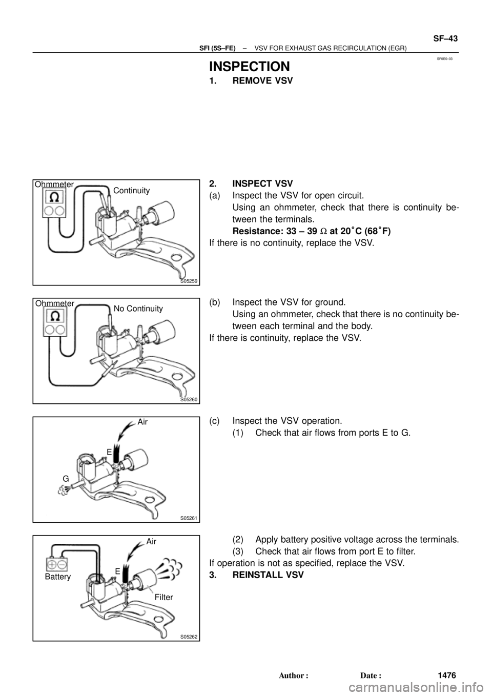
INSPECTION
1. REMOVE VSV
2. INSPECT VSV
(a) Inspect the VSV for open circuit.
Using an ohmmeter, check that there is continuity be-
tween the terminals.
Resistance: 33 ± 39 W at 20°C (68°F)
If there is no continuity, replace the VSV.
(b) Inspect the VSV for ground.
Using an ohmmeter, check that there is no continuity be-
tween each terminal and the body.
If there is continuity, replace the VSV.
(c) Inspect the VSV operation.
(1) Check that air flows from ports E to G.
(2) Apply battery positive voltage across the terminals.
(3) Check that air flows from port E to filter.
If operation is not as specified, replace the VSV.
3. REINSTALL VSV
Page 4123 of 4770
SF07K±04
S04505
S04498
S06086
Fuel Hose
Clamp
S05352
± SFI (1MZ±FE)INJECTOR
SF±23
1522 Author�: Date�:
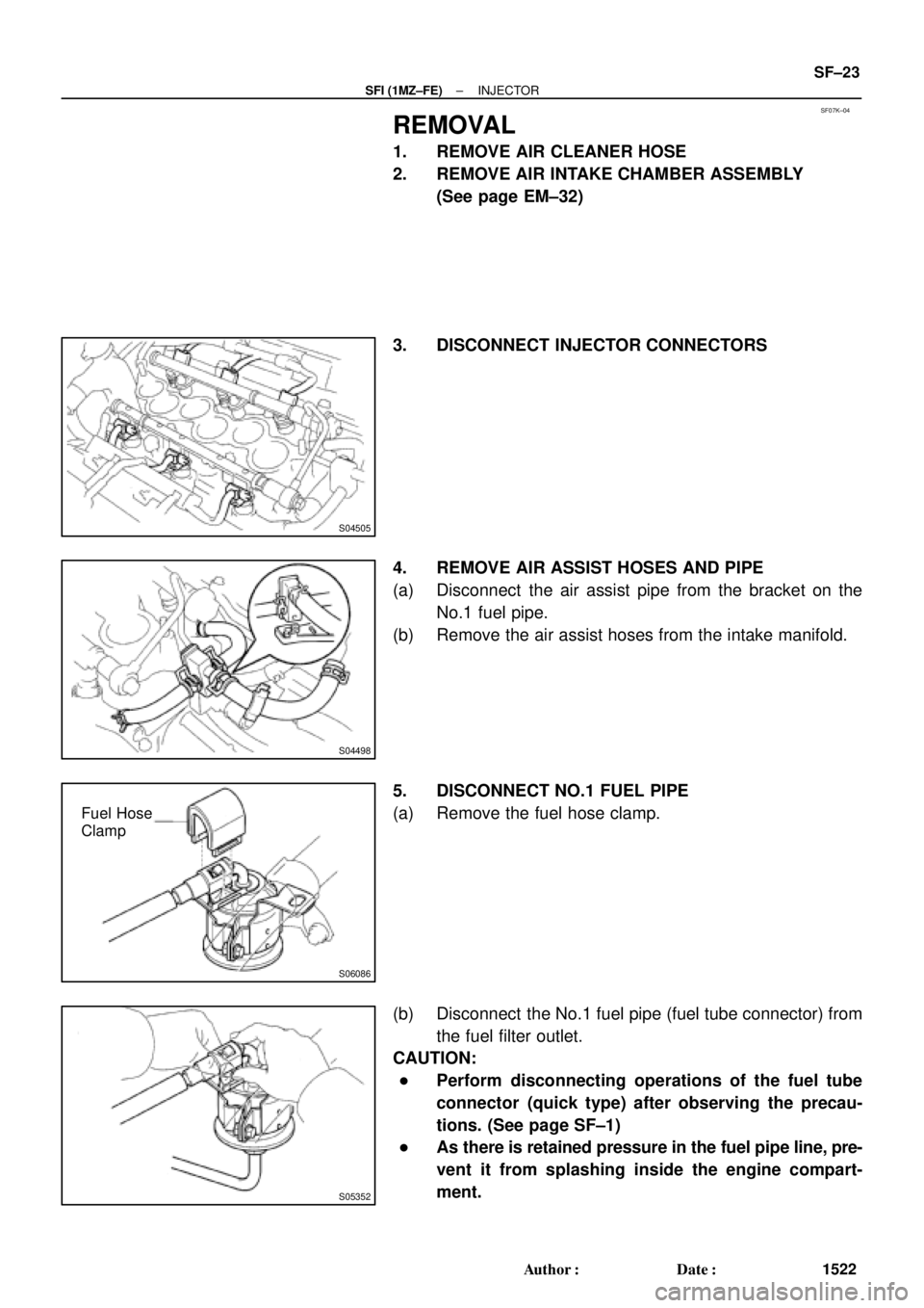
REMOVAL
1. REMOVE AIR CLEANER HOSE
2. REMOVE AIR INTAKE CHAMBER ASSEMBLY
(See page EM±32)
3. DISCONNECT INJECTOR CONNECTORS
4. REMOVE AIR ASSIST HOSES AND PIPE
(a) Disconnect the air assist pipe from the bracket on the
No.1 fuel pipe.
(b) Remove the air assist hoses from the intake manifold.
5. DISCONNECT NO.1 FUEL PIPE
(a) Remove the fuel hose clamp.
(b) Disconnect the No.1 fuel pipe (fuel tube connector) from
the fuel filter outlet.
CAUTION:
�Perform disconnecting operations of the fuel tube
connector (quick type) after observing the precau-
tions. (See page SF±1)
�As there is retained pressure in the fuel pipe line, pre-
vent it from splashing inside the engine compart-
ment.
Page 4130 of 4770
S06086
Fuel Hose
Clamp
S04498
SF±30
± SFI (1MZ±FE)INJECTOR
1529 Author�: Date�:
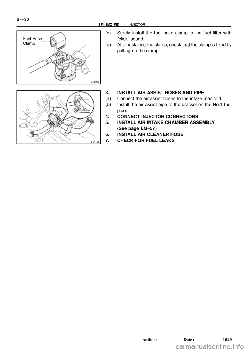
(c) Surely install the fuel hose clamp to the fuel filter with
ºclickº sound.
(d) After installing the clamp, check that the clamp is fixed by
pulling up the clamp.
3. INSTALL AIR ASSIST HOSES AND PIPE
(a) Connect the air assist hoses to the intake manifold.
(b) Install the air assist pipe to the bracket on the No.1 fuel
pipe.
4. CONNECT INJECTOR CONNECTORS
5. INSTALL AIR INTAKE CHAMBER ASSEMBLY
(See page EM±57)
6. INSTALL AIR CLEANER HOSE
7. CHECK FOR FUEL LEAKS