Page 2681 of 4770
± DIAGNOSTICSENGINE (1MZ±FE)
DI±261
496 Author�: Date�:
5 Check EGR system (See page EC±11).
NG Replace EGR system.
OK
6 Check fuel pressure (See page SF±1).
NG Check and repair fuel pump, fuel pipe line and
filter (See page SF±1).
OK
7 Check injector injection (See page SF±25).
NG Replace injector.
OK
Replace heated oxygen sensors
(bank1, 2 sensor1).
8 Perform confirmation driving pattern (See page DI±255).
Go
Page 2689 of 4770
± DIAGNOSTICSENGINE (1MZ±FE)
DI±269
504 Author�: Date�:
4 Check for spark and ignition (See page IG±1).
NG Repair or replace.
OK
5 Check fuel pressure (See page SF±21).
NG Check and repair fuel pump, pressure regulator,
fuel pipe line and filter (See page SF±1).
OK
6 Check gas leakage on exhaust system.
NG Repair or replace.
OK
Page 2693 of 4770
± DIAGNOSTICSENGINE (1MZ±FE)
DI±273
508 Author�: Date�:
1 Check air induction system (See page SF±1).
NG Repair or replace.
OK
2 Check injector injection (See page SF±21).
NG Replace injector.
OK
3 Check mass air flow meter and engine coolant temp. sensor
(See pages SF±35 and SF±63).
NG Repair or replace.
OK
4 Check for spark and ignition (See page IG±1).
NG Repair or replace.
OK
5 Check fuel pressure (See page SF±6).
NG Check and repair fuel pump, pressure regulator,
fuel pipe line and filter.
OK
Page 2701 of 4770
± DIAGNOSTICSENGINE (1MZ±FE)
DI±281
516 Author�: Date�:
4 Check resistance of injector of misfiring cylinder (See page SF±21).
NG Replace injector.
OK
Check for open and short in harness and
connector between injector and ECM
(See page IN±31).
5 Check fuel pressure (See page SF±6).
NG Check and repair fuel pump, fuel pipe line and
filter (See page SF±1).
OK
6 Check injector injection (See page SF±25).
NG Replace injector.
OK
7 Check EGR system (See page EC±11).
NG Replace EGR system.
OK
Page 2763 of 4770
± DIAGNOSTICSENGINE (1MZ±FE)
DI±343
578 Author�: Date�:
3 Check for open and short in harness and connector between ECM and A/F sen-
sors (bank 1, 2 sensor 1) (See page IN±31).
NG Repair or replace harness or connector.
OK
4 Check resistance of A/F sensor heater (See page SF±68).
NG Replace A/F sensor.
OK
5 Check air induction system (See page SF±1).
NG Repair or replace.
OK
6 Check EGR system (See page EC±11).
NG Replace EGR system.
OK
7 Check fuel pressure (See page SF±21).
NG Check and repair fuel pump, fuel pipe line and
filter (See page SF±1).
OK
Page 2767 of 4770
± DIAGNOSTICSENGINE (1MZ±FE)
DI±347
582 Author�: Date�:
3 Check for open and short in harness and connector between ECM and A/F sen-
sors (bank 1, 2 sensor 1) (See page IN±31).
NG Repair or replace harness or connector.
OK
4 Check resistance of A/F sensor heater (See page SF±68).
NG Replace A/F sensor.
OK
5 Check air induction system (See page SF±1).
NG Repair or replace.
OK
6 Check EGR system (See page EC±11).
NG Replace EGR system.
OK
7 Check fuel pressure (See page SF±21).
NG Check and repair fuel pump, fuel pipe line and
filter (See page SF±1).
OK
Page 2801 of 4770
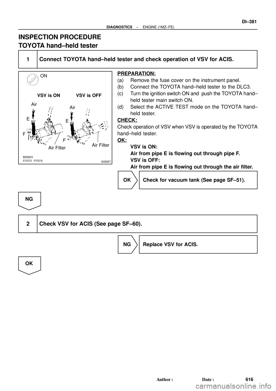
A00307
ON
VSV is ON VSV is OFF
Air Filter Air
Air
E
FE
F
BE6653
FI7073 FI7074
Air Filter
± DIAGNOSTICSENGINE (1MZ±FE)
DI±381
616 Author�: Date�:
INSPECTION PROCEDURE
TOYOTA hand±held tester
1 Connect TOYOTA hand±held tester and check operation of VSV for ACIS.
PREPARATION:
(a) Remove the fuse cover on the instrument panel.
(b) Connect the TOYOTA hand±held tester to the DLC3.
(c) Turn the ignition switch ON and push the TOYOTA hand±
held tester main switch ON.
(d) Select the ACTIVE TEST mode on the TOYOTA hand±
held tester.
CHECK:
Check operation of VSV when VSV is operated by the TOYOTA
hand±held tester.
OK:
VSV is ON:
Air from pipe E is flowing out through pipe F.
VSV is OFF:
Air from pipe E is flowing out through the air filter.
OK Check for vacuum tank (See page SF±51).
NG
2 Check VSV for ACIS (See page SF±60).
NG Replace VSV for ACIS.
OK
Page 3369 of 4770
EXHAUST GAS RECIRCULATION (EG")
EC03G±04
S05568
Cap
Filter
B06540
Vacuum Gauge
3±Way Connector
A07370
SST
E1
TE1
B06541
HOTHigh Vacuum at 2,500 rpm
Port R
Disconnect
EC±12
± EMISSION CONTROL (5S±FE)EXHAUST GAS RECIRCULATION (EGR) SYSTEM
1410 Author�: Date�:
INSPECTION
1. INSPECT EGR SYSTEM
(a) Inspect and clean the filter in the EGR vacuum modulator.
(1) Remove the cap and filter.
(2) Check the filter for contamination or damage.
(3) Using compressed air, clean the filter.
(4) Reinstall the filter and cap.
HINT:
Install the filter with the coarser surface facing the atmospheric
side (outward).
(b) Using a 3±way connector, connect a vacuum gauge to the
hose between the EGR valve and VSV.
(c) Inspect seating of the EGR valve.
Start the engine and check that the engine starts and runs
at idle.
(d) Using SST, connect terminals TE1 and E1 of the DLC1.
SST 09843±18020
(e) Inspect the VSV operation with the cold engine.
(1) The engine coolant temperature should be below
55°C (131°F).
(2) Check that the vacuum gauge indicates zero at
2,500 rpm.
(f) Inspect the operation of the VSV and EGR vacuum modu-
lator with the hot engine.
(1) Warm up the engine to above 60°C (140°F).
(2) Check that the vacuum gauge indicates low vacu-
um at 2,500 rpm.
(3) Disconnect the vacuum hose port R of the EGR vac-
uum modulator and connect port R directly to the in-
take manifold with another hose.
(4) Check that the vacuum gauge indicates high vacu-
um at 2,500 rpm.